CN219294293U - A kind of back sawing device of gypsum board production equipment - Google Patents
A kind of back sawing device of gypsum board production equipment Download PDFInfo
- Publication number
- CN219294293U CN219294293U CN202320008034.XU CN202320008034U CN219294293U CN 219294293 U CN219294293 U CN 219294293U CN 202320008034 U CN202320008034 U CN 202320008034U CN 219294293 U CN219294293 U CN 219294293U
- Authority
- CN
- China
- Prior art keywords
- gypsum board
- fixedly connected
- symmetrically
- base
- support frame
- Prior art date
- Legal status (The legal status is an assumption and is not a legal conclusion. Google has not performed a legal analysis and makes no representation as to the accuracy of the status listed.)
- Expired - Fee Related
Links
- 229910052602 gypsum Inorganic materials 0.000 title claims abstract description 67
- 239000010440 gypsum Substances 0.000 title claims abstract description 67
- 238000004519 manufacturing process Methods 0.000 title claims abstract description 31
- 230000005540 biological transmission Effects 0.000 claims abstract description 12
- 230000000670 limiting effect Effects 0.000 claims description 10
- 230000002457 bidirectional effect Effects 0.000 claims description 4
- 230000001105 regulatory effect Effects 0.000 claims 2
- 230000002146 bilateral effect Effects 0.000 claims 1
- 238000010586 diagram Methods 0.000 description 3
- 238000000034 method Methods 0.000 description 3
- 230000009286 beneficial effect Effects 0.000 description 2
- 230000000694 effects Effects 0.000 description 1
- 239000000463 material Substances 0.000 description 1
Images



Classifications
-
- Y—GENERAL TAGGING OF NEW TECHNOLOGICAL DEVELOPMENTS; GENERAL TAGGING OF CROSS-SECTIONAL TECHNOLOGIES SPANNING OVER SEVERAL SECTIONS OF THE IPC; TECHNICAL SUBJECTS COVERED BY FORMER USPC CROSS-REFERENCE ART COLLECTIONS [XRACs] AND DIGESTS
- Y02—TECHNOLOGIES OR APPLICATIONS FOR MITIGATION OR ADAPTATION AGAINST CLIMATE CHANGE
- Y02P—CLIMATE CHANGE MITIGATION TECHNOLOGIES IN THE PRODUCTION OR PROCESSING OF GOODS
- Y02P70/00—Climate change mitigation technologies in the production process for final industrial or consumer products
- Y02P70/10—Greenhouse gas [GHG] capture, material saving, heat recovery or other energy efficient measures, e.g. motor control, characterised by manufacturing processes, e.g. for rolling metal or metal working
Landscapes
- Processing Of Stones Or Stones Resemblance Materials (AREA)
Abstract
本实用新型公开了一种石膏板生产设备的回锯装置,包括底座与进板辊,所述底座顶部的一端中部固定安装有支撑架,所述支撑架的顶部固定安装有推料气缸,所述推料气缸的输出轴末端固定连接有推板,所述底座顶部远离支撑架的一端设置有石膏板放置座,所述底座远离支撑架一端的前后两侧对称固定连接有立板,两个所述立板的顶部共同固定连接有传动箱。该石膏板生产设备的回锯装置,通过设置的推料气缸、推板、石膏板放置座、丝杆、螺纹块、双轴电机、转动杆、第一斜齿轮、第二斜齿轮、第一电机、上辊、进板辊的相互配合可以实现石膏板的自动化回锯,既降低了劳动强度、节省劳动力,又合理优化了生产间隙时间的利用。

The utility model discloses a sawing device for gypsum board production equipment, which comprises a base and a board feeding roller, a support frame is fixedly installed in the middle of one end of the top of the base, and a pushing cylinder is fixedly installed on the top of the support frame. The end of the output shaft of the pusher cylinder is fixedly connected with a push plate, the end of the base top away from the support frame is provided with a gypsum board placement seat, and the front and rear sides of the end of the base far away from the support frame are symmetrically fixedly connected with vertical plates, two The top of the vertical board is fixedly connected with the transmission box. The back sawing device of the gypsum board production equipment, through the set push cylinder, push plate, gypsum board placement seat, screw rod, thread block, double-axis motor, rotating rod, first helical gear, second helical gear, first The mutual cooperation of the motor, the upper roller and the feeding roller can realize the automatic back-sawing of the gypsum board, which not only reduces the labor intensity, saves the labor force, but also reasonably optimizes the utilization of the production gap time.
Description
技术领域technical field
本实用新型涉及石膏板生产领域,特别涉及一种石膏板生产设备的回锯装置。The utility model relates to the field of gypsum board production, in particular to a back sawing device of gypsum board production equipment.
背景技术Background technique
在石膏板实际生产过程中,因设备、电气或工艺的原因,会产生部分待处理的石膏板材,这类板材会先取下生产设备,放置在待处理设备上。而等待生产间隙,还需要再将板材一一放回生产设备,这放回的过程也就是回锯。目前,石膏板的回锯通常为人工完成,人工将板材放回生产设备,费时费力,劳动强度大,工作效率也低,虽然也有一些可自动回锯的设备,但是现有的回锯设备对石膏板的限位效果较差,叠放的石膏板的侧面不平齐难以实现回锯,会影响效率。In the actual production process of gypsum board, due to equipment, electrical or process reasons, some gypsum boards to be processed will be produced. Such boards will be removed from the production equipment and placed on the equipment to be processed. While waiting for the production gap, it is necessary to put the plates back into the production equipment one by one. The process of putting them back is also called back sawing. At present, the back-sawing of gypsum boards is usually done manually. Manually putting the boards back into the production equipment is time-consuming, labor-intensive, and work-efficient. Although there are some equipment that can automatically back-saw, the existing back-sawing equipment is not The limiting effect of the gypsum boards is poor, and the sides of the stacked gypsum boards are not even and it is difficult to realize back sawing, which will affect the efficiency.
因此,提出一种石膏板生产设备的回锯装置来解决上述问题很有必要。Therefore, it is necessary to propose a back sawing device for gypsum board production equipment to solve the above problems.
实用新型内容Utility model content
本实用新型的主要目的在于提供一种石膏板生产设备的回锯装置,可以有效解决背景技术中的问题。The main purpose of the utility model is to provide a back sawing device of gypsum board production equipment, which can effectively solve the problems in the background technology.
为实现上述目的,本实用新型采取的技术方案为:In order to achieve the above object, the technical scheme that the utility model takes is:
一种石膏板生产设备的回锯装置,包括底座与进板辊,所述底座顶部的一端中部固定安装有支撑架,所述支撑架的顶部固定安装有推料气缸,所述推料气缸的输出轴末端固定连接有推板,所述底座顶部远离支撑架的一端设置有石膏板放置座,所述底座远离支撑架一端的前后两侧对称固定连接有立板,两个所述立板的顶部共同固定连接有传动箱,两个所述立板的相对一侧对称开设有凹槽,两个所述凹槽的内腔对称转动连接有丝杆,所述石膏板放置座的前后两侧中部对称固定连接有螺纹块,两个所述丝杆的顶部对称固定连接有第二斜齿轮,所述传动箱内腔的中部固定安装有双轴电机,所述双轴电机前后两侧的输出轴对称个连接有转动杆,两个所述转动杆的相远离一端对称固定连接有第一斜齿轮;A sawing device for gypsum board production equipment, comprising a base and a board feeding roller, a support frame is fixedly installed in the middle of one end of the top of the base, and a pusher cylinder is fixedly installed on the top of the support frame, and the pusher cylinder The end of the output shaft is fixedly connected with a push plate, the top end of the base away from the support frame is provided with a gypsum board placement seat, and the front and rear sides of the end far away from the support frame are symmetrically fixedly connected with vertical boards, and the two vertical boards The top is fixedly connected with the transmission box, the opposite sides of the two vertical plates are symmetrically provided with grooves, and the inner cavities of the two grooves are symmetrically connected with screw rods, and the front and rear sides of the gypsum board placement seat The middle part is symmetrically fixedly connected with a threaded block, and the tops of the two screw rods are symmetrically fixedly connected with a second helical gear. Axisymmetrical ones are connected with rotating rods, and the opposite ends of the two rotating rods are symmetrically and fixedly connected with first helical gears;
所述石膏板放置座的顶部四角对称滑动连接有导柱,所述石膏板放置座底部左右两端的前后两侧对称固定连接有固定板,前端的两个所述固定板的外侧对称固定连接有第二电机,同一端的两个所述固定板之间转动连接有双向螺杆,所述石膏板放置座顶部的左右两端对称开设有通槽,所述通槽内腔的前后两端对称插设有限位夹板;The four corners of the top of the gypsum board placement seat are symmetrically slidingly connected with guide posts, the front and rear sides of the left and right ends of the bottom of the gypsum board placement seat are symmetrically fixedly connected with fixed plates, and the outer sides of the two fixed plates at the front end are symmetrically fixedly connected with The second motor, two-way screw rods are connected between the two fixed plates at the same end, and the left and right ends of the top of the gypsum board placement seat are symmetrically provided with through grooves, and the front and rear ends of the inner cavity of the through groove are inserted symmetrically. Limited splint;
所述底座顶部远离支撑架一端的前后两侧对称固定连接有支撑板,前端的所述支撑板的上端外侧固定安装有第一电机,两个所述进板辊的上端转动连接有进板辊,两个所述支撑板的上端对称开设有调节槽,两个所述调节槽的内腔对称滑动连接有调节块,两个所述支撑板的顶部对称固定连接有调节气缸,两个所述调节块的相对一侧转动连接有上辊。The front and rear sides of the top of the base away from the end of the support frame are symmetrically fixedly connected with a support plate, the outer side of the upper end of the front end of the support plate is fixedly installed with a first motor, and the upper ends of the two feed rollers are rotatably connected with feed rollers The upper ends of the two support plates are symmetrically provided with adjustment grooves, the inner cavities of the two adjustment grooves are symmetrically slidably connected with adjustment blocks, the tops of the two support plates are symmetrically fixedly connected with adjustment cylinders, and the two The opposite side of the adjustment block is rotatably connected with an upper roller.
优选的,四个所述导柱的底部与底座的顶部固定连接,所述石膏板放置座的前后两侧中部与两个立板的相对一侧滑动配合,两个所述螺纹块分别滑动连接于两个凹槽的内腔,并且两个螺纹块分别与两个丝杆螺纹连接。Preferably, the bottoms of the four guide posts are fixedly connected to the top of the base, the middle parts of the front and rear sides of the gypsum board placement seat are slidably fitted with the opposite sides of the two vertical plates, and the two threaded blocks are respectively slidably connected In the inner cavities of the two grooves, and the two threaded blocks are threadedly connected with the two screw rods respectively.
优选的,两个所述丝杆上端分别延伸至传动箱内腔的前后两端,两个所述第二斜齿轮分别与两个第一斜齿轮啮合,所述转动杆远离双轴电机的一侧与传动箱内腔的末端壁体固定连接。Preferably, the upper ends of the two screw rods respectively extend to the front and rear ends of the inner chamber of the transmission box, the two second helical gears mesh with the two first helical gears respectively, and the rotating rod is far away from one of the two shaft motors. The side is fixedly connected with the end wall body of the inner cavity of the transmission box.
优选的,两个所述双向螺杆的前端分别与两个第二电机的输出轴固定连接,两组所述限位夹板的下端分别与两个双向螺杆螺纹连接,并且限位夹板与通槽滑动配合。Preferably, the front ends of the two two-way screws are respectively fixedly connected to the output shafts of the two second motors, the lower ends of the two sets of limiting splints are respectively threaded with the two two-way screws, and the limiting splints slide with the through grooves Cooperate.
优选的,所述第一电机可带动进板辊转动,所述进板辊的顶部与推板对应,所述调节槽位于进板辊的上方。Preferably, the first motor can drive the plate-feeding roller to rotate, the top of the plate-feeding roller corresponds to the push plate, and the adjustment groove is located above the plate-feeding roller.
优选的,所述调节气缸底部的输出端延伸至调节槽的内腔并与调节块的顶部固定连接。Preferably, the output end of the bottom of the adjustment cylinder extends to the inner cavity of the adjustment tank and is fixedly connected with the top of the adjustment block.
有益效果Beneficial effect
与现有技术相比,本实用新型提供了一种石膏板生产设备的回锯装置,具备以下有益效果:Compared with the prior art, the utility model provides a sawing device for gypsum board production equipment, which has the following beneficial effects:
1、该石膏板生产设备的回锯装置,通过设置的推料气缸、推板、石膏板放置座、丝杆、螺纹块、双轴电机、转动杆、第一斜齿轮、第二斜齿轮、第一电机、上辊、进板辊的相互配合可以实现石膏板的自动化回锯,既降低了劳动强度、节省劳动力,又合理优化了生产间隙时间的利用,提高了生产效率,导柱便于对石膏板放置座进行导向。1. The back sawing device of the gypsum board production equipment, through the set push cylinder, push plate, gypsum board placement seat, screw rod, thread block, double-axis motor, rotating rod, first helical gear, second helical gear, The cooperation of the first motor, the upper roller and the feeding roller can realize the automatic sawing of the gypsum board, which not only reduces the labor intensity and saves labor, but also rationally optimizes the use of the production gap time and improves the production efficiency. The guide column is easy to adjust Plasterboard placement blocks for guidance.
2、该石膏板生产设备的回锯装置,限位夹板、双向螺杆、第二电机的设置便于对叠放在石膏板放置座顶部的石膏板进行限位,使得侧面平齐,便于回锯。2. The back-sawing device of the gypsum board production equipment, the limiting splint, the two-way screw, and the second motor are set to facilitate the positioning of the gypsum boards stacked on the top of the gypsum board placing seat, so that the sides are flush and easy to re-saw.
3、该石膏板生产设备的回锯装置,通过设置的调节气缸、调节块、调节槽的相互配合可以调节上辊的高度,进而改变上辊与进板辊之间的距离,可以适应不同厚度的石膏板。3. The back sawing device of the gypsum board production equipment can adjust the height of the upper roller through the cooperation of the set adjustment cylinder, adjustment block and adjustment groove, and then change the distance between the upper roller and the board feeding roller, which can adapt to different thicknesses plasterboard.
附图说明Description of drawings
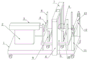
图1是本实用新型的结构示意图;Fig. 1 is the structural representation of the utility model;
图2是本实用新型图1中A处放大图;Fig. 2 is the enlarged view of place A in Fig. 1 of the utility model;
图3是本实用新型两个支撑板上端的结构示意图;Fig. 3 is a structural schematic diagram of the upper ends of two support plates of the utility model;
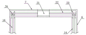
图4是本实用新型传动箱和立板连接处的侧视剖面结构示意图;Fig. 4 is a side view sectional structure schematic diagram of the connection between the transmission box and the vertical plate of the utility model;
图5是本实用新型石膏板放置座的侧视结构示意图。Fig. 5 is a side view structural schematic diagram of the gypsum board placement seat of the present invention.
图中:1、底座;2、支撑架;3、推料气缸;4、推板;5、石膏板放置座;6、立板;7、传动箱;8、导柱;9、限位夹板;10、通槽;11、支撑板;12、进板辊;13、上辊;14、凹槽;15、螺纹块;16、丝杆;17、调节块;18、调节气缸;19、调节槽;20、第一电机;21、双轴电机;22、转动杆;23、第一斜齿轮;24、第二斜齿轮;25、固定板;26、双向螺杆;27、第二电机。In the figure: 1. base; 2. support frame; 3. push cylinder; 4. push plate; ;10, through groove; 11, support plate; 12, plate feed roller; 13, upper roller; 14, groove; 15, thread block; 16, screw mandrel; 17, adjustment block; 18, adjustment cylinder; 20, the first motor; 21, the biaxial motor; 22, the rotating rod; 23, the first helical gear; 24, the second helical gear; 25, the fixed plate; 26, the two-way screw; 27, the second motor.
具体实施方式Detailed ways
为使本实用新型实现的技术手段、创作特征、达成目的与功效易于明白了解,下面结合具体实施方式,进一步阐述本实用新型。In order to make the technical means, creative features, goals and effects achieved by the utility model easy to understand, the utility model will be further elaborated below in conjunction with specific embodiments.
如图1-5所示,一种石膏板生产设备的回锯装置,包括底座1与进板辊12,底座1顶部的一端中部固定安装有支撑架2,支撑架2的顶部固定安装有推料气缸3,推料气缸3的输出轴末端固定连接有推板4,底座1顶部远离支撑架2的一端设置有石膏板放置座5,底座1远离支撑架2一端的前后两侧对称固定连接有立板6,石膏板放置座5的前后两侧中部与两个立板6的相对一侧滑动配合,两个立板6的顶部共同固定连接有传动箱7,两个立板6的相对一侧对称开设有凹槽14,两个凹槽14的内腔对称转动连接有丝杆16,石膏板放置座5的前后两侧中部对称固定连接有螺纹块15,两个螺纹块15分别滑动连接于两个凹槽14的内腔,并且两个螺纹块15分别与两个丝杆16螺纹连接,两个丝杆16上端分别延伸至传动箱7内腔的前后两端,两个丝杆16的顶部对称固定连接有第二斜齿轮24,传动箱7内腔的中部固定安装有双轴电机21,双轴电机21前后两侧的输出轴对称个连接有转动杆22,转动杆22远离双轴电机21的一侧与传动箱7内腔的末端壁体固定连接,两个转动杆22的相远离一端对称固定连接有第一斜齿轮23,两个第二斜齿轮24分别与两个第一斜齿轮23啮合;As shown in Figures 1-5, a sawing device for gypsum board production equipment includes a base 1 and a
石膏板放置座5的顶部四角对称滑动连接有导柱8,四个导柱8的底部与底座1的顶部固定连接,导柱8便于对石膏板放置座5进行导向,石膏板放置座5底部左右两端的前后两侧对称固定连接有固定板25,前端的两个固定板25的外侧对称固定连接有第二电机27,同一端的两个固定板25之间转动连接有双向螺杆26,两个双向螺杆26的前端分别与两个第二电机27的输出轴固定连接,石膏板放置座5顶部的左右两端对称开设有通槽10,通槽10内腔的前后两端对称插设有限位夹板9,两组限位夹板9的下端分别与两个双向螺杆26螺纹连接,并且限位夹板9与通槽10滑动配合,限位夹板9、双向螺杆26、第二电机27的设置便于对叠放在石膏板放置座5顶部的石膏板进行限位,使得侧面平齐,便于回锯;The four corners of the top of the gypsum
底座1顶部远离支撑架2一端的前后两侧对称固定连接有支撑板11,前端的支撑板11上端的外侧固定安装有第一电机20,两个进板辊12的上端转动连接有进板辊12,进板辊12的顶部与推板4对应,第一电机20可带动进板辊12转动,两个支撑板11的上端对称开设有调节槽19,调节槽19位于进板辊12的上方,两个调节槽19的内腔对称滑动连接有调节块17,两个支撑板11的顶部对称固定连接有调节气缸18,调节气缸18底部的输出端延伸至调节槽19的内腔并与调节块17的顶部固定连接,两个调节块17的相对一侧转动连接有上辊13,通过设置的调节气缸18、调节块17、调节槽19的相互配合可以调节上辊13的高度,进而改变上辊13与进板辊12之间的距离,可以适应不同厚度的石膏板,通过设置的推料气缸3、推板4、石膏板放置座5、丝杆16、螺纹块15、双轴电机21、转动杆22、第一斜齿轮23、第二斜齿轮24、第一电机20、上辊13、进板辊12的相互配合可以实现石膏板的自动化回锯,既降低了劳动强度、节省劳动力,又合理优化了生产间隙时间的利用,提高了生产效率。The front and rear sides of the top of the base 1 away from the end of the support frame 2 are symmetrically fixedly connected with a
需要说明的是,本实用新型为一种石膏板生产设备的回锯装置,使用时石膏板层层叠放于石膏板放置座5的顶部,然后启动两个第二电机27带动两个双向螺杆26转动,两个双向螺杆26带动两组限位夹板9对石膏板的两侧进行限位夹持,使得侧面平齐,然后启动调节气缸18带动调节块17上下位移,调节上辊13的高度,使得上辊13与进板辊12之间的距离与石膏板的厚度适配,启动双轴电机21带动转动杆22转动,转动杆22通过第一斜齿轮23和第二斜齿轮24带动两个丝杆16转动,两个丝杆16通过两个螺纹块15带动石膏板放置座5上升,使得最上方的石膏板与推板4对应,然后启动推料气缸3带动推板4推动最上方的石膏板,使得石膏板进入进板辊12和上辊13之间,启动第一电机20,第一电机20带动进板辊12转动,配合上辊13可将石膏板输送至生产设备上。It should be noted that the utility model is a sawing device for gypsum board production equipment. When in use, gypsum boards are stacked on the top of the gypsum
以上显示和描述了本实用新型的基本原理和主要特征和本实用新型的优点。本行业的技术人员应该了解,本实用新型不受上述实施例的限制,上述实施例和说明书中描述的只是说明本实用新型的原理,在不脱离本实用新型精神和范围的前提下,本实用新型还会有各种变化和改进,这些变化和改进都落入要求保护的本实用新型范围内。本实用新型要求保护范围由所附的权利要求书及其等效物界定。The basic principles and main features of the present utility model and the advantages of the present utility model have been shown and described above. Those skilled in the industry should understand that the utility model is not limited by the above-mentioned embodiments. The above-mentioned embodiments and descriptions only illustrate the principles of the utility model. Without departing from the spirit and scope of the utility model, the utility model The new model also has various changes and improvements, and these changes and improvements all fall within the scope of the claimed utility model. The scope of protection required by the utility model is defined by the appended claims and their equivalents.
Claims (6)
Priority Applications (1)
| Application Number | Priority Date | Filing Date | Title |
|---|---|---|---|
| CN202320008034.XU CN219294293U (en) | 2023-01-04 | 2023-01-04 | A kind of back sawing device of gypsum board production equipment |
Applications Claiming Priority (1)
| Application Number | Priority Date | Filing Date | Title |
|---|---|---|---|
| CN202320008034.XU CN219294293U (en) | 2023-01-04 | 2023-01-04 | A kind of back sawing device of gypsum board production equipment |
Publications (1)
| Publication Number | Publication Date |
|---|---|
| CN219294293U true CN219294293U (en) | 2023-07-04 |
Family
ID=86958443
Family Applications (1)
| Application Number | Title | Priority Date | Filing Date |
|---|---|---|---|
| CN202320008034.XU Expired - Fee Related CN219294293U (en) | 2023-01-04 | 2023-01-04 | A kind of back sawing device of gypsum board production equipment |
Country Status (1)
| Country | Link |
|---|---|
| CN (1) | CN219294293U (en) |
-
2023
- 2023-01-04 CN CN202320008034.XU patent/CN219294293U/en not_active Expired - Fee Related
Similar Documents
| Publication | Publication Date | Title |
|---|---|---|
| CN220462993U (en) | Automatic sheet turning equipment | |
| CN108637045B (en) | An automatic bending device for wire threading trough cover for easy material picking | |
| CN114260375B (en) | A hot pressing device for machining high-precision alloy copper strip to prevent edge cracking | |
| CN115178586A (en) | Special roller for rolling electronic copper foil | |
| CN219520320U (en) | Steel bar continuous bending device | |
| CN219563909U (en) | A material extruding device for the production of fireproof board | |
| CN218663641U (en) | Automatic feeding mechanism for machining | |
| CN216065839U (en) | Accurate cutting of photovoltaic frame extra quality is with cutting machine | |
| CN211616548U (en) | Degradable Plastic Twin Screw Extruder | |
| CN209851865U (en) | A feeding device for riding a dragon | |
| CN212070115U (en) | A stable expanded metal mesh machine | |
| CN218947051U (en) | A CNC engraving machine feeding device | |
| CN222094399U (en) | A CNC bending machine with a guide mechanism | |
| CN221776977U (en) | A PCBA loading machine | |
| CN221312004U (en) | Slip table hydraulic plate bender | |
| CN223224002U (en) | Paperboard processing compacting device | |
| CN220864116U (en) | Cutting device is used in building materials production | |
| CN222873357U (en) | A degumming jig | |
| CN218699717U (en) | Double-end adjustable woodworking cutting mechanism | |
| CN222781135U (en) | A whole plate clamping and film feeding structure for a blister machine | |
| CN219403179U (en) | Modularized production device for aluminum plate with beautiful core | |
| CN217253251U (en) | Production rubber roll is with adjustable cutting device | |
| CN206296663U (en) | Bender | |
| CN223147349U (en) | Automatic unilateral adjustable cladding machine | |
| CN220688636U (en) | Electromechanical device fixed bolster |
Legal Events
| Date | Code | Title | Description |
|---|---|---|---|
| GR01 | Patent grant | ||
| GR01 | Patent grant | ||
| CF01 | Termination of patent right due to non-payment of annual fee |
Granted publication date: 20230704 |
|
| CF01 | Termination of patent right due to non-payment of annual fee |