CN219286480U - Battery module pressurizing device - Google Patents
Battery module pressurizing device Download PDFInfo
- Publication number
- CN219286480U CN219286480U CN202320242761.2U CN202320242761U CN219286480U CN 219286480 U CN219286480 U CN 219286480U CN 202320242761 U CN202320242761 U CN 202320242761U CN 219286480 U CN219286480 U CN 219286480U
- Authority
- CN
- China
- Prior art keywords
- pressing
- plate
- battery module
- assembly
- side pushing
- Prior art date
- Legal status (The legal status is an assumption and is not a legal conclusion. Google has not performed a legal analysis and makes no representation as to the accuracy of the status listed.)
- Active
Links
- 238000003825 pressing Methods 0.000 claims abstract description 188
- 230000007246 mechanism Effects 0.000 claims abstract description 80
- 239000000758 substrate Substances 0.000 claims description 7
- 230000000881 depressing effect Effects 0.000 claims 1
- 238000000034 method Methods 0.000 description 3
- WHXSMMKQMYFTQS-UHFFFAOYSA-N Lithium Chemical compound [Li] WHXSMMKQMYFTQS-UHFFFAOYSA-N 0.000 description 2
- 229910052744 lithium Inorganic materials 0.000 description 2
- 238000004519 manufacturing process Methods 0.000 description 2
- 230000008569 process Effects 0.000 description 2
- 230000008859 change Effects 0.000 description 1
- 238000005056 compaction Methods 0.000 description 1
- 230000006835 compression Effects 0.000 description 1
- 238000007906 compression Methods 0.000 description 1
- 238000006073 displacement reaction Methods 0.000 description 1
- 210000001503 joint Anatomy 0.000 description 1
- 230000004048 modification Effects 0.000 description 1
- 238000012986 modification Methods 0.000 description 1
- 238000006467 substitution reaction Methods 0.000 description 1
Images



Classifications
-
- Y—GENERAL TAGGING OF NEW TECHNOLOGICAL DEVELOPMENTS; GENERAL TAGGING OF CROSS-SECTIONAL TECHNOLOGIES SPANNING OVER SEVERAL SECTIONS OF THE IPC; TECHNICAL SUBJECTS COVERED BY FORMER USPC CROSS-REFERENCE ART COLLECTIONS [XRACs] AND DIGESTS
- Y02—TECHNOLOGIES OR APPLICATIONS FOR MITIGATION OR ADAPTATION AGAINST CLIMATE CHANGE
- Y02P—CLIMATE CHANGE MITIGATION TECHNOLOGIES IN THE PRODUCTION OR PROCESSING OF GOODS
- Y02P70/00—Climate change mitigation technologies in the production process for final industrial or consumer products
- Y02P70/50—Manufacturing or production processes characterised by the final manufactured product
Landscapes
- Battery Mounting, Suspending (AREA)
Abstract
The utility model provides a battery module pressurizing device, which comprises two side pushing and pressing mechanism modules oppositely arranged along a first direction, wherein each side pushing and pressing mechanism module comprises at least two side pushing and pressing mechanisms, and at least two side pushing and pressing mechanisms are arranged side by side along a second direction; the side pushing and pressing mechanism comprises a lower pressing plate, a side pushing plate, a side elastic pressing assembly, a pressing driving assembly and a side pushing driving assembly, wherein the pressing driving assembly is connected with the lower pressing plate and used for driving the lower pressing plate to press or loosen the upper end face of the battery module; the side pushing driving assembly is used for driving the side pushing plate to press or loosen the side face of the battery module; the lateral elastic pressing assembly is arranged on the downward-pressing driving assembly and connected with the lateral pushing plate, and the lateral elastic pressing assembly is used for driving the lateral pushing plate to press to the side face of the battery module at the pressing position. The battery module pressurizing device provided by the utility model is compatible to compress battery modules of different models through a plurality of side pushing and pressing mechanisms.
Description
Technical Field
The utility model relates to the technical field of battery modules, in particular to a battery module pressurizing device.
Background
In lithium battery module enterprises, different serial-parallel module production and model changing are often carried out according to the PACK technology. At present, a module pressurizing device of a lithium battery module bundling machine is generally fixed, a module corresponds to a set of module pressurizing device, after the module size is changed, for example, after the size is reduced, the length of a module lateral pressurizing device is unchanged, so that the module longitudinal pressurizing device can interfere with two ends of the module lateral pressurizing device in the length direction in the compacting process, longitudinal compaction cannot be realized, that is, when the module is changed, the module pressurizing device needs to be changed together, and therefore, the time for changing, installing and debugging is longer, and the production is influenced. Therefore, in order to improve the mold changing efficiency of the mold and simultaneously ensure the bundling quality of the mold, it is highly desirable to develop a mold pressing device which is convenient for mold changing.
Disclosure of Invention
Aiming at the problem that the existing battery module pressurizing device cannot be compatible with battery modules of different types, the utility model provides a battery module pressurizing device.
The utility model provides a battery module pressurizing device, which comprises two side pushing and pressing mechanism modules oppositely arranged along a first direction, wherein each side pushing and pressing mechanism module comprises at least two side pushing and pressing mechanisms, and at least two side pushing and pressing mechanisms are arranged side by side along a second direction; the side pushing and pressing mechanism comprises a lower pressing plate, a side pushing plate, a side elastic pressing assembly, a pressing driving assembly and a side pushing driving assembly, wherein the pressing driving assembly is connected with the lower pressing plate and used for driving the lower pressing plate to press or loosen the upper end face of the battery module; the side pushing driving assembly is used for driving the side pushing plate to press or loosen the side face of the battery module; the lateral elastic pressurizing assembly is arranged on the pressing driving assembly and connected with the lateral pushing plate, and the lateral elastic pressurizing assembly is used for driving the lateral pushing plate to press the lateral surface of the battery module at a pressing position.
Optionally, the side pushing and pressing mechanisms of the two side pushing and pressing mechanism modules are arranged in a mirror symmetry mode, and lengths of the side pushing plates on the side pushing and pressing mechanisms of more than two side pushing and pressing mechanism modules along the second direction are not identical.
Optionally, the side pushing driving assembly comprises a base plate, a mounting frame, a side pushing cylinder, a first sliding rail and a first sliding block, and the side pushing plate and the lower pressing plate are respectively arranged on the mounting frame; the first sliding rail is arranged on the base plate and extends along a first direction, and the mounting frame is in sliding connection with the first sliding rail through the first sliding block; the lateral elastic pressurizing assembly is arranged on the base plate, the base plate is connected with the lateral pushing air cylinder, and the lateral pushing air cylinder is used for driving the base plate to move along a first direction so that the lateral pushing plate can press or loosen the lateral surface of the battery module.
Optionally, the lateral elastic pressurization assembly includes a first mounting plate and a plurality of first elastic components, the first mounting plate set up in on the base plate, and with the side push plate parallel arrangement, a plurality of first elastic components interval set up in on the first mounting plate, and with the side push plate is connected.
Optionally, the side pushing and pressing mechanism further includes two parallel second sliding rails and a second sliding block arranged on the second sliding rails, the second sliding rails extend along the first direction, and one surface of the substrate, which is away from the first sliding rails, is in sliding connection with the second sliding rails through the second sliding blocks.
Optionally, the side pushing and pressing mechanism further includes a first limiting component, the first limiting component includes a stop block and a limiting plate, the stop block is disposed on one side of the second sliding rail, the limiting plate is disposed on the base plate, and the limiting plate extends out of one side of the base plate to be in butt joint with the stop block.
Optionally, the side pushing and pressing mechanism further includes a second limiting component, the second limiting component includes a plurality of first limiting blocks and a plurality of second limiting blocks, a plurality of first limiting blocks are respectively arranged at two ends of the first sliding rail, and a plurality of second limiting blocks are respectively arranged at two ends of the second sliding rail.
Optionally, the side pushing and pressing mechanism further includes a pressing elastic pressing assembly, where the pressing elastic pressing assembly includes a second mounting plate and a plurality of second elastic pieces, the second mounting plate is connected with the pressing driving assembly, the second mounting plate is disposed on the mounting frame, and the plurality of second elastic pieces are disposed on the second mounting plate at intervals and connected with the pressing plate; the pressing driving assembly is connected with the second mounting plate and used for driving the second mounting plate to move along a third direction, so that the pressing plate presses or releases the upper end face of the battery module.
Optionally, the pressing driving component comprises a pressing cylinder, a connecting seat, a third sliding rail and a third sliding block arranged on the third sliding rail, wherein the third sliding rail is arranged on the mounting frame and extends along a third direction; the output of cylinder down with the connecting seat is connected, connecting seat one side with the second mounting panel is connected, the opposite side of connecting seat with the third slider is connected, the cylinder down is used for driving the connecting seat is followed the third slide rail slides, so as to drive the second mounting panel is along the third direction removal.
Optionally, the battery module pressurizing device further comprises an end pressing mechanism and a tray for placing the battery module, the end pressing mechanism comprises a positioning component, an end pressing component and a bottom plate, the tray is arranged on the bottom plate, and the positioning component and the end pressing component are respectively arranged at two ends of the tray along a second direction and used for pressing two ends of the battery module;
the positioning assembly comprises a first motor, a first screw rod assembly, a first connecting piece and a positioning piece, wherein the first connecting piece is connected with the first screw rod assembly, the positioning piece is arranged on the first connecting piece, the first motor is connected with the first screw rod assembly and is used for driving the first connecting piece to move along a second direction so as to drive the positioning piece to press or loosen one end of the battery module;
the end part compressing assembly comprises a second motor, a second screw rod assembly, a second connecting piece and a compressing piece, wherein the second connecting piece is connected with the second screw rod assembly, the compressing piece is arranged on the second connecting piece, the second motor is connected with the second screw rod assembly and used for driving the second connecting piece to move along a second direction so as to drive the compressing piece to compress or loosen the other end of the battery module.
Optionally, the end pressing mechanism further includes a guide member, where the guide member includes two fourth sliding rails and a plurality of fourth sliding blocks, the two fourth sliding rails are disposed on the bottom plate in parallel, the two fourth sliding rails are disposed on two sides of the tray respectively, and the fourth sliding rails extend along the second direction; and each fourth sliding rail is provided with two fourth sliding blocks, and the first connecting piece and the second connecting piece are respectively connected with the fourth sliding blocks on the two fourth sliding rails.
According to the utility model, the plurality of side pushing and pressing mechanisms are arranged to be respectively matched with the battery modules with different lengths, when the types of the battery modules are changed, the corresponding side pushing and pressing mechanisms are used for pressing the battery modules, and a space exists between the side pushing plate of the non-working side pushing and pressing mechanism and the battery modules, so that the position interference of the end pressing mechanism is effectively avoided, and the battery modules with different types are pressed. By arranging the lateral elastic pressurizing assembly, when the lateral pushing driving assembly drives the lateral pushing plate to press the side face of the battery module, pressure continuously pressing the side face of the battery module is provided for the lateral pushing plate. The upper end face of the battery module is pre-shaped by arranging the lower pressing plate, so that the battery pole in the battery module is guaranteed to be on the same plane. Through setting up the side push pedal, carry out the plastic in advance to the battery module, the bundling of battery module of being convenient for.
Drawings
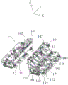
Fig. 1 is a schematic structural view of a battery module pressurizing device according to an embodiment of the present utility model;
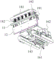
fig. 2 is a schematic structural view of a side pushing and pressing mechanism of a battery module pressing device according to an embodiment of the present utility model;
fig. 3 is a schematic view illustrating a structure of a side pushing and pressing mechanism of a battery module pressurizing device according to another embodiment of the present utility model;
fig. 4 is a schematic view illustrating a structure of a side pushing and pressing mechanism of a battery module pressurizing device according to another embodiment of the present utility model;
fig. 5 is a schematic structural view of an end pressing mechanism of a battery module pressing device according to an embodiment of the present utility model.
Reference numerals in the drawings of the specification are as follows:
1. a side pushing and pressing mechanism; 11. a lower pressing plate; 12. a side push plate; 13. a lateral elastic pressing assembly; 131. a first mounting plate; 132. a first elastic member; 141. a substrate; 142. a mounting frame; 143. a side pushing cylinder; 144. a first slide rail; 145. a first slider; 151. a second slide rail; 152. a second slider; 161. a stop block; 162. a limiting plate; 171. a first limiting block; 172. a second limiting block; 181. a second mounting plate; 182. a second elastic member; 191. a pressing cylinder; 192. a connecting seat; 193. a third slide rail;
2. a positioning assembly; 21. a first lead screw assembly; 22. a first connector; 23. a positioning piece;
3. an end hold down assembly; 31. a second motor; 32. a second lead screw assembly; 33. a second connector; 34. a pressing member;
4. a battery module; 5. a bottom plate;
61. a fourth slide rail; 62. and a fourth slider.
Detailed Description
The present utility model will be described in further detail with reference to the drawings and examples, in order to make the objects, technical solutions and advantages of the present utility model more apparent. It should be understood that the specific embodiments described herein are for purposes of illustration only and are not intended to limit the scope of the utility model.
In order to illustrate the technical scheme of the utility model, the following description is made by specific examples.
As shown in fig. 1 to 5, a battery module pressurizing device according to an embodiment of the present utility model includes two side pushing and pressing mechanism modules disposed opposite to each other along a first direction, the side pushing and pressing mechanism modules including at least two side pushing and pressing mechanisms 1, at least two of the side pushing and pressing mechanisms 1 being disposed side by side along a second direction. The side pushing and pressing mechanism 1 comprises a pressing plate 11, a side pushing plate 12, a side elastic pressing component 13, a pressing driving component and a side pushing driving component, wherein the pressing driving component is connected with the pressing plate 11 and used for driving the pressing plate 11 to press or loosen the upper end face of the battery module 4. The side pushing driving assembly is used for driving the side pushing plate 12 to press or loosen the side face of the battery module 4. The lateral elastic pressing component 13 is arranged on the pressing driving component and is connected with the lateral pushing plate 12, and the lateral elastic pressing component 13 is used for driving the lateral pushing plate 12 to press to the side face of the battery module 4 in a pressing position.
Here, the plurality of side pushing and pressing mechanisms 1 may be controlled by the same driving source through different control methods to press the battery modules 4 respectively. The plurality of side pushing and pressing mechanisms 1 are respectively matched with the battery modules 4 with different lengths, and the lengths of the side pushing plates 12 and the lower pressing plates 11 are different.
The working process of the battery module pressurizing device comprises the following steps: when the battery module 4 moves between the side pushing and pressing mechanisms 1, in the side pushing and pressing mechanisms 1 on two sides of the battery module 4, the side pushing and driving assembly drives the side pushing plate 12 to press the side face of the battery module 4, and the pressing and driving assembly drives the lower pressing plate 11 to press the upper end face of the battery module 4. Then the side pushing and pressing mechanism 1 releases the compression of the battery module 4, and the battery module 4 moves to the bundling position.
In the embodiment of the utility model, the plurality of side pushing and pressing mechanisms 1 are arranged to be respectively matched with the battery modules 4 with different lengths, when the types of the battery modules 4 are changed, the corresponding side pushing and pressing mechanisms 1 are used for pressing the battery modules 4, and the space between the side pushing plate 12 of the non-working side pushing and pressing mechanism 1 and the battery modules 4 is reserved, so that the position interference of the end pressing mechanism is effectively avoided, and the pressing of the battery modules 4 with different types is realized. By providing the lateral elastic pressing member 13, the lateral pushing plate 12 is provided with a pressure continuously pressing against the side face of the battery module 4 when the lateral pushing plate 12 is driven by the lateral pushing driving member to press against the side face of the battery module 4. The upper end face of the battery module 4 is pre-shaped by arranging the lower pressing plate 11, so that the battery poles in the battery module 4 are guaranteed to be on the same plane. By providing the side push plate 12, the battery module 4 is pre-shaped, so that the battery module 4 is conveniently bundled.
As shown in fig. 1 to 4, a coordinate system is provided in a space where the side pushing and pressing mechanism 1 is located, and a first direction is defined as an X direction, which is a width direction of the battery module 4. The second direction is defined as the Y direction, which is the length direction of the battery module 4, that is, the arrangement direction of the unit cells in the battery module 4, and is horizontally perpendicular to the first direction. The third direction is defined as the Z direction, which is the height direction of the battery module 4.
As shown in fig. 1, in some embodiments of the present utility model, the side pushing and pressing mechanisms 1 of two side pushing and pressing mechanism modules are arranged in mirror symmetry, and lengths of the side pushing plates 12 on more than two side pushing and pressing mechanisms 1 in one side pushing and pressing mechanism module are not identical along the second direction, so as to facilitate matching of battery modules 4 with different lengths.
In one embodiment, the lengths of the battery modules 4 respectively matched with the side pushing and pressing mechanisms 1 are 500, 300 and 300, so that the battery modules 4 with the lengths of 300, 500, 800 and 1100 can be matched at the same time. When the length of the battery module 4 is changed, only different side pushing and pressing mechanisms 1 are required to be driven to press. Meanwhile, the side pushing and pressing mechanism 1 which is not controlled to press is not positioned on the same horizontal line with the side pushing and pressing mechanism 1 positioned at the pressing position, so that the position interference of the end part pressing mechanism is effectively avoided.
In some embodiments of the present utility model, the side pushing driving assembly includes a base plate 141, a mounting frame 142, a side pushing cylinder 143, a first sliding rail 144 and a first sliding block 145, and the side pushing plate 12 and the lower pressing plate 11 are respectively disposed on the mounting frame 142. The first sliding rail 144 is disposed on the base plate 141 and extends along the X direction, and the mounting rack 142 is slidably connected with the first sliding rail 144 through the first slider 145. The lateral elastic pressing assembly 13 is disposed on the base plate 141, the base plate 141 is connected with the lateral pushing air cylinder 143, and the lateral pushing air cylinder 143 is used for driving the base plate 141 to move along the X direction, so that the lateral pushing plate 12 presses or releases the lateral surface of the battery module 4. Specifically, a push-down drive assembly is disposed on the mounting bracket 142.
In the present embodiment, the side pushing cylinder 143 drives the substrate 141 to move in the X direction, and the mounting frame 142 drives the lower pressure plate 11 and the side pushing plate 12 to move toward the battery module 4 until the side pushing plate 12 abuts against the side surface of the battery module 4. The lower pressing plate 11 is driven by the lower pressing driving assembly to press the upper end face of the battery module 4, then the side pushing air cylinder 143 continues to drive the base plate 141 to move along the X direction, the mounting frame 142 is in sliding connection with the first sliding rail 144 through the first sliding block 145, the positions of the side pushing plate 12 and the lower pressing plate 11 are kept unchanged, the side elastic pressing assembly 13 on the base plate 141 is compressed, and the side pushing plate 12 is driven to press the side face of the battery module 4.
As shown in fig. 1 and 2, in some embodiments of the present utility model, the lateral elastic pressing assembly 13 includes a first mounting plate 131 and a plurality of first elastic members 132, wherein the first mounting plate 131 is disposed on the base plate 141 and is disposed parallel to the lateral pushing plate 12, and the plurality of first elastic members 132 are disposed on the first mounting plate 131 at intervals and are connected to the lateral pushing plate 12. Specifically, the first elastic member 132 is a spring.
As shown in fig. 1 to fig. 4, in some embodiments of the present utility model, the side pushing and pressing mechanism 1 further includes two second sliding rails 151 disposed in parallel and a second sliding block 152 disposed on the second sliding rails 151, where the second sliding rails 151 extend along the X direction, and a surface of the substrate 141 facing away from the first sliding rail 144 is slidably connected to the second sliding rails 151 through the second sliding block 152. By providing the second slide rail 151 and the second slider 152, the substrate 141 is ensured to slide smoothly in the X direction.
As shown in fig. 2 and 4, in some embodiments of the present utility model, the side pushing and pressing mechanism 1 further includes a first limiting assembly, the first limiting assembly includes a stop block 161 and a limiting plate 162, the stop block 161 is disposed on one side of the second slide rail 151, the limiting plate 162 is disposed on the base plate 141, and the limiting plate 162 extends out of one side of the base plate 141 to be abutted with the stop block 161. By providing the stopper 161 and the stopper 162, the displacement of the side push plate 12 in the X direction is restricted.
As shown in fig. 2 to fig. 4, in some embodiments of the present utility model, the side pushing and pressing mechanism 1 further includes a second limiting assembly, where the second limiting assembly includes a plurality of first limiting blocks 171 and a plurality of second limiting blocks 172, the plurality of first limiting blocks 171 are respectively disposed at two ends of the first sliding rail 144 to prevent the mounting frame 142 from sliding out of the first sliding rail 144, and the plurality of second limiting blocks 172 are respectively disposed at two ends of the second sliding rail 151 to prevent the substrate 141 from sliding out of the second sliding rail 151.
As shown in fig. 1 and 3, in some embodiments of the present utility model, the side pushing and pressing mechanism 1 further includes a pressing elastic pressing assembly, where the pressing elastic pressing assembly includes a second mounting plate 181 and a plurality of second elastic members 182, the second mounting plate 181 is connected to the pressing driving assembly, the second mounting plate 181 is disposed on the mounting frame 142, and the plurality of second elastic members 182 are disposed on the second mounting plate 181 at intervals and connected to the pressing plate 11. The pressing driving assembly is connected with the second mounting plate 181, and is used for driving the second mounting plate 181 to move along the Z direction, so that the pressing plate 11 presses or releases the upper end face of the battery module 4. An elastic pressure is applied to the lower press plate 11 by providing the second elastic member 182 to press the upper end surface of the battery module 4. Specifically, the second elastic member 182 is a spring.
As shown in fig. 2 and 4, in some embodiments of the present utility model, the pressing driving assembly includes a pressing cylinder 191, a connection seat 192, a third sliding rail 193, and a third slider (not shown) disposed on the third sliding rail 193, wherein the third sliding rail 193 is disposed on the mounting frame 142, and the third sliding rail 193 extends along the Z direction. The output end of the pressing cylinder 191 is connected with the connecting seat 192, one side of the connecting seat 192 is connected with the second mounting plate 181, the other side of the connecting seat 192 is connected with the third sliding block, and the pressing cylinder 191 is used for driving the connecting seat 192 to slide along the third sliding rail 193 so as to drive the second mounting plate 181 to move along the Z direction. By providing the third slide rail 193 and the third slider, the lower platen 11 is ensured to move smoothly in the Z direction.
Specifically, the number of the pressing cylinders 191 is different according to the lengths of the battery modules 4 adapted to the side pushing and pressing mechanism 1, and when the lengths of the battery modules 4 adapted to the side pushing and pressing mechanism 1 are long, in order to ensure that the pressing plate 11 is stably lifted, the number of the pressing cylinders 191 is two, and the two pressing cylinders 191 are respectively arranged on two sides of the mounting frame 142. When the length of the battery module 4 to which the side pushing and pressing mechanism 1 is adapted is short, the pressing cylinder 191 is provided as one.
As shown in fig. 5, in some embodiments of the present utility model, the battery module pressurizing device further includes an end pressing mechanism including a positioning member 2, an end pressing member 3, and a bottom plate 5, and a tray (not shown) for placing the battery module 4, the tray being disposed on the bottom plate 5, and the positioning member 2 and the end pressing member 3 being disposed at both ends of the tray in the Y direction, respectively, for pressing both ends of the battery module 4.
The positioning assembly 2 comprises a first motor (not shown in the figure), a first screw rod assembly 21, a first connecting piece 22 and a positioning piece 23, wherein the first connecting piece 22 is connected with the first screw rod assembly 21, the positioning piece 23 is arranged on the first connecting piece 22, the first motor is connected with the first screw rod assembly 21 and is used for driving the first connecting piece 22 to move along the Y direction so as to drive the positioning piece 23 to press or release one end of the battery module 4.
The end part compressing assembly 3 comprises a second motor 31, a second screw rod assembly 32, a second connecting piece 33 and a compressing piece 34, the second connecting piece 33 is connected with the second screw rod assembly 32, the compressing piece 34 is arranged on the second connecting piece 33, the second motor 31 is connected with the second screw rod assembly 32 and is used for driving the second connecting piece 33 to move along the Y direction so as to drive the compressing piece 34 to compress or loosen the other end of the battery module 4.
By arranging the positioning assembly 2 and the end part compressing assembly 3, the battery modules 4 with different lengths are compressed, and when the modules are in a mold change, the positions of the positioning pieces 23 are only required to be adjusted, so that the whole set of end part compressing mechanism is not required to be replaced. Specifically, when the battery module 4 is in the bundling position, after the positioning assembly 2 moves a preset distance to one end of the battery module 4, the end pressing assembly 3 moves in the direction of the positioning assembly 2, and pressure is applied to the battery module 4 from the other end of the battery module 4, so that the positioning assembly 2 and the end pressing assembly 3 press the two ends of the battery module 4.
As shown in fig. 5, in some embodiments of the present utility model, the end pressing mechanism further includes a guide member, where the guide member includes two fourth sliding rails 61 and a plurality of fourth sliding blocks 62, the two fourth sliding rails 61 are disposed on the bottom plate 5 in parallel, and the two fourth sliding rails 61 are disposed on two sides of the tray, respectively, and the fourth sliding rails 61 extend along the Y direction. Two fourth sliders 62 are disposed on each of the fourth slide rails 61, and the first connecting member 22 and the second connecting member 33 are respectively connected with the fourth sliders 62 on the two fourth slide rails 61. By providing the fourth slide rail 61 and the fourth slider 62, the first link 22 and the second link 33 are smoothly moved in the Y direction.
The above embodiments are only for illustrating the technical solution of the present utility model, and are not limiting. Although the utility model has been described in detail with reference to the foregoing embodiments, it will be understood by those of ordinary skill in the art that: the technical scheme described in the foregoing embodiments can be modified or some of the technical features thereof can be replaced by equivalents. Such modifications and substitutions do not depart from the spirit and scope of the technical solutions of the embodiments of the present utility model, and are intended to be included in the scope of the present utility model.
Claims (10)
1. The battery module pressurizing device is characterized by comprising two side pushing and pressing mechanism modules which are oppositely arranged along a first direction, wherein each side pushing and pressing mechanism module comprises at least two side pushing and pressing mechanisms, and at least two side pushing and pressing mechanisms are arranged side by side along a second direction; the side pushing and pressing mechanism comprises a lower pressing plate, a side pushing plate, a side elastic pressing assembly, a pressing driving assembly and a side pushing driving assembly, wherein the pressing driving assembly is connected with the lower pressing plate and used for driving the lower pressing plate to press or loosen the upper end face of the battery module; the side pushing driving assembly is used for driving the side pushing plate to press or loosen the side face of the battery module; the lateral elastic pressurizing assembly is arranged on the pressing driving assembly and connected with the lateral pushing plate, and the lateral elastic pressurizing assembly is used for driving the lateral pushing plate to press the lateral surface of the battery module at a pressing position.
2. The battery module pressurizing device according to claim 1, wherein the side pushing and pressing mechanisms of the two side pushing and pressing mechanism modules are arranged in mirror symmetry, and lengths of the side pushing plates on the side pushing and pressing mechanisms of more than two of the side pushing and pressing mechanism modules in the second direction are not identical.
3. The battery module pressurizing device according to claim 1, wherein the side pushing driving assembly comprises a base plate, a mounting frame, a side pushing cylinder, a first sliding rail and a first sliding block, and the side pushing plate and the lower pressing plate are respectively arranged on the mounting frame; the first sliding rail is arranged on the base plate and extends along a first direction, and the mounting frame is in sliding connection with the first sliding rail through the first sliding block; the lateral elastic pressurizing assembly is arranged on the base plate, the base plate is connected with the lateral pushing air cylinder, and the lateral pushing air cylinder is used for driving the base plate to move along a first direction so that the lateral pushing plate can press or loosen the lateral surface of the battery module.
4. The battery module pressurizing device according to claim 3, wherein the lateral elastic pressurizing assembly comprises a first mounting plate and a plurality of first elastic members, the first mounting plate is disposed on the base plate and is disposed parallel to the lateral pushing plate, and the plurality of first elastic members are disposed on the first mounting plate at intervals and are connected to the lateral pushing plate.
5. The battery module pressurizing device according to claim 3, wherein the side pushing and pressing mechanism further comprises two second sliding rails arranged in parallel and second sliding blocks arranged on the second sliding rails, the second sliding rails extend along the first direction, and one surface of the substrate, which is away from the first sliding rails, is in sliding connection with the second sliding rails through the second sliding blocks.
6. The battery module pressurizing device of claim 5, wherein the side pushing and depressing mechanism further comprises a first limiting assembly, the first limiting assembly comprises a stop block and a limiting plate, the stop block is arranged on one side of the second sliding rail, the limiting plate is arranged on the base plate, and the limiting plate extends out of one side of the base plate to be in abutting connection with the stop block.
7. The battery module pressurizing device of claim 5, wherein the side pushing and pressing mechanism further comprises a second limiting assembly, the second limiting assembly comprises a plurality of first limiting blocks and a plurality of second limiting blocks, the plurality of first limiting blocks are respectively arranged at two ends of the first sliding rail, and the plurality of second limiting blocks are respectively arranged at two ends of the second sliding rail.
8. The battery module pressurizing device according to claim 3, wherein the side pushing and pressing mechanism further comprises a pressing elastic pressurizing assembly, the pressing elastic pressurizing assembly comprises a second mounting plate and a plurality of second elastic pieces, the second mounting plate is connected with the pressing driving assembly, the second mounting plate is arranged on the mounting frame, and the plurality of second elastic pieces are arranged on the second mounting plate at intervals and are connected with the pressing plate; the pressing driving assembly is connected with the second mounting plate and used for driving the second mounting plate to move along a third direction, so that the pressing plate presses or releases the upper end face of the battery module.
9. The battery module pressurizing device of claim 8, wherein the pressing driving assembly comprises a pressing cylinder, a connecting seat, a third sliding rail and a third sliding block arranged on the third sliding rail, the third sliding rail is arranged on the mounting frame, and the third sliding rail extends along a third direction; the output of cylinder down with the connecting seat is connected, connecting seat one side with the second mounting panel is connected, the opposite side of connecting seat with the third slider is connected, the cylinder down is used for driving the connecting seat is followed the third slide rail slides, so as to drive the second mounting panel is along the third direction removal.
10. The battery module pressurizing device according to claim 1, further comprising an end pressing mechanism and a tray for placing the battery module, wherein the end pressing mechanism comprises a positioning component, an end pressing component and a bottom plate, the tray is arranged on the bottom plate, and the positioning component and the end pressing component are respectively arranged at two ends of the tray along a second direction and are used for pressing two ends of the battery module;
the positioning assembly comprises a first motor, a first screw rod assembly, a first connecting piece and a positioning piece, wherein the first connecting piece is connected with the first screw rod assembly, the positioning piece is arranged on the first connecting piece, the first motor is connected with the first screw rod assembly and is used for driving the first connecting piece to move along a second direction so as to drive the positioning piece to press or loosen one end of the battery module;
the end part compressing assembly comprises a second motor, a second screw rod assembly, a second connecting piece and a compressing piece, wherein the second connecting piece is connected with the second screw rod assembly, the compressing piece is arranged on the second connecting piece, the second motor is connected with the second screw rod assembly and used for driving the second connecting piece to move along a second direction so as to drive the compressing piece to compress or loosen the other end of the battery module.
Priority Applications (1)
| Application Number | Priority Date | Filing Date | Title |
|---|---|---|---|
| CN202320242761.2U CN219286480U (en) | 2023-02-07 | 2023-02-07 | Battery module pressurizing device |
Applications Claiming Priority (1)
| Application Number | Priority Date | Filing Date | Title |
|---|---|---|---|
| CN202320242761.2U CN219286480U (en) | 2023-02-07 | 2023-02-07 | Battery module pressurizing device |
Publications (1)
| Publication Number | Publication Date |
|---|---|
| CN219286480U true CN219286480U (en) | 2023-06-30 |
Family
ID=86939191
Family Applications (1)
| Application Number | Title | Priority Date | Filing Date |
|---|---|---|---|
| CN202320242761.2U Active CN219286480U (en) | 2023-02-07 | 2023-02-07 | Battery module pressurizing device |
Country Status (1)
| Country | Link |
|---|---|
| CN (1) | CN219286480U (en) |
Cited By (2)
| Publication number | Priority date | Publication date | Assignee | Title |
|---|---|---|---|---|
| CN116885369A (en) * | 2023-07-21 | 2023-10-13 | 江苏烽禾升智能科技有限公司 | A module fixing device and multi-specification module heating and pressurizing equipment |
| CN117712512A (en) * | 2024-01-11 | 2024-03-15 | 伟尔泰克智造科技(苏州)有限公司 | An automatic pressing and unlocking mechanism for lithium battery modules |
-
2023
- 2023-02-07 CN CN202320242761.2U patent/CN219286480U/en active Active
Cited By (2)
| Publication number | Priority date | Publication date | Assignee | Title |
|---|---|---|---|---|
| CN116885369A (en) * | 2023-07-21 | 2023-10-13 | 江苏烽禾升智能科技有限公司 | A module fixing device and multi-specification module heating and pressurizing equipment |
| CN117712512A (en) * | 2024-01-11 | 2024-03-15 | 伟尔泰克智造科技(苏州)有限公司 | An automatic pressing and unlocking mechanism for lithium battery modules |
Similar Documents
| Publication | Publication Date | Title |
|---|---|---|
| CN211556054U (en) | Heating and shaping mechanism of modular battery | |
| CN206415798U (en) | Soft-package battery module lug hold-down mechanism | |
| CN113716330A (en) | Mechanism and hold-down mechanism are got to fecund article clamp | |
| CN113547263A (en) | Battery module welding and fixing device and fixing method | |
| CN217596321U (en) | Battery module side seam welding frock | |
| CN113458781B (en) | End cover equipment | |
| CN205159438U (en) | Pressure device of battery module | |
| CN116111176B (en) | Battery pack processing equipment capable of aligning battery cells and working method thereof | |
| CN219311136U (en) | Clamping device for battery cell | |
| CN220740833U (en) | Positioning mechanism of electric core and steel casing and semi-automatic kludge of electric core and steel casing | |
| CN213711534U (en) | Mould snatchs hold-down mechanism | |
| CN218926130U (en) | Semi-automatic core pulling and riveting equipment | |
| CN217280906U (en) | Folding device | |
| CN207668217U (en) | A kind of high-efficiency high-accuracy bender | |
| CN213137839U (en) | Pushing type hot-pressing equipment for assembly | |
| CN211916614U (en) | Compress tightly carrier and accredited testing organization | |
| CN218928509U (en) | U-shaped water gap shearing tool for automobile injection molding part | |
| CN214236906U (en) | Compressing quick-change mechanism for welding square battery bus board | |
| CN222088666U (en) | Shaping device and battery module production equipment | |
| CN222326537U (en) | Pin bending jig | |
| CN222945321U (en) | Slide rail lock both sides limit support positioner | |
| CN224042177U (en) | Copper bar bending machine | |
| CN222680111U (en) | Multi-lens product assembling and pressing machine | |
| CN222308610U (en) | Workpiece positioning device and processing equipment | |
| CN223198932U (en) | A linkage clamping and positioning device |
Legal Events
| Date | Code | Title | Description |
|---|---|---|---|
| GR01 | Patent grant | ||
| GR01 | Patent grant |