CN219259103U - Self-adhesive coiled material splitting machine - Google Patents
Self-adhesive coiled material splitting machine Download PDFInfo
- Publication number
- CN219259103U CN219259103U CN202320312466.XU CN202320312466U CN219259103U CN 219259103 U CN219259103 U CN 219259103U CN 202320312466 U CN202320312466 U CN 202320312466U CN 219259103 U CN219259103 U CN 219259103U
- Authority
- CN
- China
- Prior art keywords
- motor
- main body
- self
- wall
- plate
- Prior art date
- Legal status (The legal status is an assumption and is not a legal conclusion. Google has not performed a legal analysis and makes no representation as to the accuracy of the status listed.)
- Expired - Fee Related
Links
Images

Classifications
-
- Y—GENERAL TAGGING OF NEW TECHNOLOGICAL DEVELOPMENTS; GENERAL TAGGING OF CROSS-SECTIONAL TECHNOLOGIES SPANNING OVER SEVERAL SECTIONS OF THE IPC; TECHNICAL SUBJECTS COVERED BY FORMER USPC CROSS-REFERENCE ART COLLECTIONS [XRACs] AND DIGESTS
- Y02—TECHNOLOGIES OR APPLICATIONS FOR MITIGATION OR ADAPTATION AGAINST CLIMATE CHANGE
- Y02P—CLIMATE CHANGE MITIGATION TECHNOLOGIES IN THE PRODUCTION OR PROCESSING OF GOODS
- Y02P70/00—Climate change mitigation technologies in the production process for final industrial or consumer products
- Y02P70/10—Greenhouse gas [GHG] capture, material saving, heat recovery or other energy efficient measures, e.g. motor control, characterised by manufacturing processes, e.g. for rolling metal or metal working
Landscapes
- Replacement Of Web Rolls (AREA)
Abstract
Description
技术领域technical field
本实用新型涉及卷材分切机技术领域,更具体地说,涉及自粘卷材分切机。The utility model relates to the technical field of coil cutting machines, in particular to a self-adhesive coil cutting machine.
背景技术Background technique
分切机是一种将宽幅纸张、薄膜等各种卷材分切成多条窄幅材料的机械设备,在造纸领域和印刷包装领域被广泛应用,目前应用的防水卷材分切机,主要是将防水卷材纵向分切,按照一定的需求分切出不同规格的防水卷材;但是目前的防水卷材分切机,大部分都是只能分切固定规格的卷桐,既只能纵向分切出固定规格的防水卷材,不能作宽度的调节,并且不能一次纵向分切出多道防水卷材,如果需要一次纵向分切出多道防水卷材,就需要专用的设备进行分切,这就造成了投资的浪费,增加了生产成本,而且应用上也很不方便。The slitting machine is a kind of mechanical equipment that cuts various rolls such as wide-width paper and film into multiple narrow-width materials. It is widely used in the field of papermaking and printing and packaging. The currently used waterproof roll slitting machine, It mainly cuts the waterproof membrane longitudinally, and cuts waterproof membranes of different specifications according to certain requirements; It can longitudinally cut waterproof membranes of fixed specifications, but cannot adjust the width, and cannot cut out multiple waterproof membranes longitudinally at one time. If it is necessary to cut multiple waterproof membranes longitudinally at one time, special equipment is required. Cutting, which has caused a waste of investment, increased production costs, and is also very inconvenient in application.
针对以上问题,申请号CN200920026424.X,申请名称为自粘防水卷材滚刀分切机,所记载的,包括机架,机架的上部设置有滚刀轴,机架的下部设置有收卷轴,收卷轴与动力传动装置相连,滚刀轴包括上滚刀轴和下滚刀轴,上滚刀轴上设置有上滚刀,下滚刀轴上设置有下滚刀,上滚刀和下滚刀对应设置;由于上滚刀与上滚刀轴可拆卸连接,下滚刀与下滚刀轴可拆卸连接,所以,可以根据需要调节上滚刀和下滚刀在上滚刀轴和下滚刀轴上的位置,从而可以分切出不同宽度的防水卷材,也可以根据需要增加或减少上滚刀和下滚刀的数量,从而可以一次分切出多道防水卷材,并且还可以一次分切出多道宽度不同的防水卷材,使用非常方便,减少了重复性投资,减低了生产成本。In view of the above problems, the application number CN200920026424.X, the application name is self-adhesive waterproof coiled material hob slitting machine, the record includes the frame, the upper part of the frame is provided with a hob shaft, and the bottom part of the frame is provided with a winding shaft , the rewinding shaft is connected with the power transmission device, the hob shaft includes an upper hob shaft and a lower hob shaft, the upper hob shaft is provided with an upper hob, the lower hob shaft is provided with a lower hob, the upper hob and the lower hob Corresponding setting of the hob; since the upper hob is detachably connected to the upper hob shaft, and the lower hob is detachably connected to the lower hob shaft, the upper hob and the lower hob can be adjusted according to the needs. The position on the hob shaft, so that waterproof membranes of different widths can be cut out, and the number of upper hobs and lower hobs can also be increased or decreased according to needs, so that multiple waterproof membranes can be cut at one time, and also It can cut out multiple waterproof membranes with different widths at one time, which is very convenient to use, reduces repeated investment, and reduces production costs.
虽然该装置有益效果较多,但依然存在下列问题:无法实现对自粘卷材的长度进行有效横切,其次调整滚刀需要人工进行调刀,使用时效率低其次给使用者增加不必要的体力浪费。Although the device has many beneficial effects, there are still the following problems: the length of the self-adhesive coil cannot be effectively cut across, and secondly, the adjustment of the hob requires manual adjustment of the knife, which is inefficient and secondly adds unnecessary trouble to the user. Physical waste.
鉴于此,我们提出自粘卷材分切机。In view of this, we propose self-adhesive coil slitting machine.
实用新型内容Utility model content
1.要解决的技术问题1. technical problem to be solved
本实用新型的目的在于提供自粘卷材分切机,以解决上述背景技术中提出的问题。The purpose of this utility model is to provide a self-adhesive coil cutting machine to solve the problems raised in the above-mentioned background technology.
2.技术方案2. Technical solution
一种自粘卷材分切机,包括主体,其特征在于:所述主体前方外壁设置有控制箱,所述主体外壁设置有结构相同的第一导向装置和第二导向装置,所述主体前后外壁还焊接有支撑板,所述支撑板上焊接有支撑活动板,所述支撑板上开设有滑槽,所述滑槽内部滑动连接有纵切装置,所述支撑板固定安装有横切装置,所述横切装置包括横切刀具放置箱,所述横切刀具放置箱内腔顶部固定安装有第一固定支撑板,所述第一固定支撑板下方设置有多个气缸,多个所述气缸下方连接有刀座,所述刀座下方卡接有横切刀,所述横切刀具放置箱下方开设有与横切刀相匹配的贯通槽,所述横切刀具放置箱内腔底部设置有刮板,所述主体顶部开设有与横切刀相匹配的刀槽,所述主体顶部外壁还设置有测长传感器,所述主体顶部中间位置开设有放置箱,所述主体一侧设置有收卷装置,所述第一导向装置、第二导向装置、横切装置、气缸、测长传感器、收卷装置与控制箱电性连接。A self-adhesive coil slitting machine, including a main body, characterized in that: the front outer wall of the main body is provided with a control box, the outer wall of the main body is provided with a first guide device and a second guide device with the same structure, the front and rear of the main body The outer wall is also welded with a support plate, the support plate is welded with a supporting movable plate, a chute is opened on the support plate, a slitting device is slidably connected inside the chute, and a cross-cutting device is fixedly installed on the support plate , the cross-cutting device includes a cross-cutting knife placement box, a first fixed support plate is fixedly installed on the top of the inner cavity of the cross-cutting knife placement box, a plurality of cylinders are arranged under the first fixed support plate, and a plurality of the A knife seat is connected to the bottom of the cylinder, and a cross-cutting knife is clamped under the knife seat. A through groove matching the cross-cutting knife is provided under the box for placing the cross-cutting knife. There is a scraper, the top of the main body is provided with a knife groove matching the cross-cutting knife, the outer wall of the top of the main body is also provided with a length measuring sensor, the middle position of the top of the main body is provided with a storage box, and one side of the main body is provided with a The winding device, the first guiding device, the second guiding device, the cross-cutting device, the cylinder, the length measuring sensor, and the winding device are electrically connected to the control box.
作为一种优选方案:所述第一导向装置包括固定板一,所述固定板一上设置有导向辊电机,所述导向辊电机输出端连接有导向辊,所述导向辊末端连接有固定板二,所述固定板二固定安装在主体上,所述固定板一和固定板二中部活动连接有牵引辊,所述第二导向装置设置在主体的顶部一侧,所述导向辊电机与控制箱电性连接。As a preferred solution: the first guiding device includes a fixed plate one, a guide roller motor is arranged on the fixed plate one, a guide roller is connected to the output end of the guide roller motor, and a fixed plate is connected to the end of the guide roller Two, the fixed plate 2 is fixedly installed on the main body, the middle part of the fixed plate 1 and the fixed plate 2 is movably connected with a traction roller, the second guide device is arranged on the top side of the main body, and the guide roller motor is connected with the control Box electrical connection.
作为一种优选方案:所述纵切装置包括支撑活动板,所述支撑活动板顶部固定安装有升降电机,所述升降电机输出端连接有升降杆,所述升降杆穿过支撑活动板后连接有纵切刀具放置箱,所述纵切刀具放置箱外壁设置有与滑槽相匹配的滑块,所述升降电机与控制箱电性连接。As a preferred solution: the slitting device includes a supporting movable plate, a lifting motor is fixedly installed on the top of the supporting movable plate, the output end of the lifting motor is connected with a lifting rod, and the lifting rod is connected after passing through the supporting movable plate There is a storage box for slitting knives, the outer wall of the storage box for slitting knives is provided with a slider matching the chute, and the lifting motor is electrically connected with the control box.
作为一种优选方案:所述纵切刀具放置箱内壁利用螺丝固定有齿条板,所述齿条板外壁套接有调节块,所述调节块内部上方焊接有卡接块,所述调节块上方固定安装有转动电机,所述转动电机输出端设置有转动杆,所述转动杆末端连接有与齿条板相匹配的齿轮,所述调节块下方焊接有移动块,所述移动块下表面焊接有第三固定支撑板,多个所述第三固定支撑板外壁固定安装有切割电机,所述转动电机和切割电机与控制箱电性连接。As a preferred solution: the inner wall of the slitting tool placement box is fixed with a rack plate by screws, the outer wall of the rack plate is sleeved with an adjustment block, and a clamping block is welded on the inside of the adjustment block, and the adjustment block A rotating motor is fixedly installed above, the output end of the rotating motor is provided with a rotating rod, the end of the rotating rod is connected with a gear matching the rack plate, a moving block is welded below the adjusting block, and the lower surface of the moving block A third fixed support plate is welded, cutting motors are fixedly installed on the outer walls of the plurality of third fixed support plates, and the rotating motor and cutting motor are electrically connected to the control box.
作为一种优选方案:所述切割电机输出端连接有驱动杆,所述驱动杆末端焊接有固定刀座,所述固定刀座利用螺丝固定安装有纵切刀,所述主体顶部外壁对应着纵切刀开设有半圆槽。As a preferred solution: the output end of the cutting motor is connected to a drive rod, the end of the drive rod is welded with a fixed knife seat, and the fixed knife seat is fixed with a longitudinal cutter by screws, and the outer wall of the top of the main body corresponds to the longitudinal The cutter is provided with a semicircular groove.
作为一种优选方案:所述放置箱内腔底部固定安装有调节电机,所述调节电机输出端连接有调节杆,所述调节杆上方连接有调节板,所述调节板上方设置有多个滚动球,所述放置箱上设置有拉门,所述调节电机与控制箱电性连接。As a preferred solution: an adjustment motor is fixedly installed at the bottom of the inner cavity of the storage box, an adjustment rod is connected to the output end of the adjustment motor, an adjustment plate is connected above the adjustment rod, and a plurality of scroll bars are arranged above the adjustment plate. The ball is provided with a sliding door on the storage box, and the adjustment motor is electrically connected with the control box.
作为一种优选方案:所述收卷装置包括固定座,所述主体两侧均设置有固定座,所述固定座焊接在主体外壁,所述第二固定支撑板侧壁利用螺丝固定安装有驱动收卷电机,所述驱动收卷电机输出端连接有收卷轴,所述驱动收卷电机与控制箱电性连接。As a preferred solution: the winding device includes a fixing seat, and both sides of the main body are provided with a fixing seat, and the fixing seat is welded on the outer wall of the main body, and the side wall of the second fixed support plate is fixed with a drive A winding motor, the output end of the driving winding motor is connected with a winding shaft, and the driving winding motor is electrically connected with the control box.
3.有益效果3. Beneficial effect
相比于现有技术,本实用新型的优点在于:可以有效的对自粘卷材的长度进行有效横切,其次还可以更加便捷的多种尺寸和厚度的自粘卷材进行纵切,避免人力的浪费且有效的提高分切效率,实用性强。Compared with the prior art, the utility model has the advantages that: the length of the self-adhesive coil can be effectively cross-cut, and secondly, self-adhesive coils of various sizes and thicknesses can be longitudinally cut more conveniently, avoiding It saves manpower and effectively improves the cutting efficiency, which is very practical.
附图说明Description of drawings
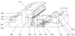
图1为本实用新型的整体结构示意图;Fig. 1 is the overall structural representation of the utility model;
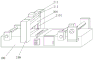
图2为本实用新型的纵切装置连接结构示意图;Fig. 2 is a schematic diagram of the connection structure of the slitting device of the present invention;
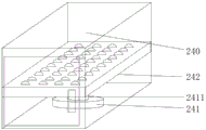
图3为本实用新型的放置箱结构示意图;Fig. 3 is a schematic structural view of the placement box of the present utility model;
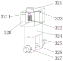
图4为本实用新型的纵切装置连接结构示意图;Fig. 4 is a schematic diagram of the connection structure of the slitting device of the present invention;
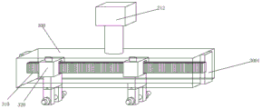
图5为本实用新型的纵切装置内部结构示意图;Fig. 5 is a schematic diagram of the internal structure of the slitting device of the present invention;
图6为本实用新型的刀具固定装置结构示意图;Fig. 6 is a structural schematic diagram of the tool fixing device of the present invention;
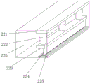
图7为本实用新型的横切装置内部结构示意图;Fig. 7 is a schematic diagram of the internal structure of the cross-cutting device of the present invention;
图中标号说明:100、主体;110、控制箱;200、固定板一;201、导向辊电机;202、导向辊;203、牵引辊;204、固定板二;210、支撑板;2101、滑槽;211、支撑活动板;212、升降电机;220、横切刀具放置箱;221、第一固定支撑板;222、气缸;223、刀座;224、横切刀;225、刮板;230、测长传感器;240、放置箱;241、调节电机;2411、调节杆;242、调节板;250、固定座;251、第二固定支撑板;252、驱动收卷电机;253、收卷轴;300、纵切刀具放置箱;3001、滑块;310、齿条板;320、调节块;321、转动电机;3211、转动杆;322、齿轮;323、卡接块;324、移动块;325、第三固定支撑板;326、纵切刀;327、切割电机;328、驱动杆;329、固定刀座。Label explanation among the figure: 100, main body; 110, control box; 200, fixed plate one; 201, guide roller motor; 202, guide roller; 203, traction roller; 204, fixed plate two; 210, support plate; Groove; 211, supporting movable plate; 212, lifting motor; 220, cross-cutting tool placement box; 221, the first fixed support plate; 222, cylinder; 223, knife seat; 224, cross-cutting knife; 225, scraper; 230 , length measuring sensor; 240, placement box; 241, adjustment motor; 2411, adjustment rod; 242, adjustment plate; 250, fixed seat; 251, second fixed support plate; 252, drive winding motor; 300, slitting tool placement box; 3001, slide block; 310, rack plate; 320, adjustment block; 321, rotating motor; 3211, rotating rod; 322, gear; , the third fixed support plate; 326, slitting knife; 327, cutting motor; 328, drive rod; 329, fixed knife seat.
具体实施方式Detailed ways
请参阅图1-7,本实用新型提供一种技术方案:Please refer to Figure 1-7, the utility model provides a technical solution:
自粘卷材分切机,包括主体100,主体100前方外壁设置有控制箱110,主体100外壁设置有结构相同的第一导向装置和第二导向装置,主体100前后外壁还焊接有支撑板210,支撑板210上焊接有支撑活动板211,支撑板210上开设有滑槽2101,滑槽2101内部滑动连接有纵切装置,支撑板210固定安装有横切装置,横切装置包括横切刀具放置箱220,横切刀具放置箱220内腔顶部固定安装有第一固定支撑板221,第一固定支撑板221下方设置有多个气缸222,多个气缸222下方连接有刀座223,气缸222与外部常规充气泵进行连接,方便对气泵进行有效的输出气压,对刀座223进行升降切割,刀座223下方卡接有横切刀224,横切刀具放置箱220下方开设有与横切刀224相匹配的贯通槽,横切刀具放置箱220内腔底部设置有刮板225,刮板225为橡胶材质,可以有效的对横切刀224上方粘连的异物进行清理,避免由于异物的粘连而影响对自粘卷材的横向分切。The self-adhesive coil slitting machine includes a
主体100顶部开设有与横切刀224相匹配的刀槽,主体100顶部外壁还设置有测长传感器230,测长传感器230以整个镜头中的某一点在镜头中的不同位置来判断被测物的长度,有两个端口:一个发射端口,发出LED光源;一个是高速拍照端口,实现CCD面积高速成像对比,通过在极短时间内的两个时间的图像对比,分辨被测物体移动的长度,主体100顶部中间位置开设有放置箱240,主体100一侧设置有收卷装置,第一导向装置、第二导向装置、横切装置、气缸222、测长传感器230、收卷装置与控制箱110电性连接,可以有效的对自粘卷材进行有效切割,其次还可以利用测长传感器230对自粘卷材进行检测距离,使其可以有效的将自粘卷材切割为不同长度的成品。The top of the
在一些实施例中;可在主体左侧外部设置独立的放卷设备,可配合对未分切的材料进行放卷,配合分切器对自粘卷材进行分切。In some embodiments, an independent unwinding device can be set outside the left side of the main body, which can be used to unwind the uncut material and cut the self-adhesive roll with the divider.
具体的,第一导向装置包括固定板一200,固定板一200上设置有导向辊电机201,导向辊电机201输出端连接有导向辊202,导向辊202末端连接有固定板二204,固定板二204固定安装在主体100上,固定板一200和固定板二204中部活动连接有牵引辊203,第二导向装置设置在主体100的顶部一侧,导向辊电机201与控制箱110电性连接,可以有效的对自粘卷材进行导向和驱动,使其方便配合分切机对其进行分切。Specifically, the first guiding device includes a fixed plate one 200, a
进一步的,纵切装置包括支撑活动板211,支撑活动板211顶部固定安装有升降电机212,升降电机212输出端连接有升降杆,升降杆穿过支撑活动板211后连接有纵切刀具放置箱300,纵切刀具放置箱300外壁设置有与滑槽2101相匹配的滑块3001,升降电机212与控制箱110电性连接,可以有效的不同厚度的自粘卷材进行分切,其次还能将其上升,方便对横切装置对自粘卷材进行横向分切。Further, the slitting device includes a supporting
再进一步的,纵切刀具放置箱300内壁利用螺丝固定有齿条板310,齿条板310外壁套接有调节块320,调节块320内部上方焊接有卡接块323,调节块320上方固定安装有转动电机321,转动电机321输出端设置有转动杆3211,转动杆3211末端连接有与齿条板310相匹配的齿轮322,调节块320下方焊接有移动块324,移动块324下表面焊接有第三固定支撑板325,多个第三固定支撑板325外壁固定安装有切割电机327,转动电机321和切割电机327与控制箱110电性连接,可以有效便捷的将自粘卷材分切为不同尺寸宽度的成品。Furthermore, the inner wall of the slitting
更进一步的,切切割电机327输出端连接有驱动杆328,驱动杆328末端焊接有固定刀座329,固定刀座329利用螺丝固定安装有纵切刀326,主体100顶部外壁对应着纵切刀326开设有半圆槽,可以更好配合纵切刀326对自粘卷材进行纵向分切。Furthermore, the output end of the
具体的,放置箱240内腔底部固定安装有调节电机241,调节电机241输出端连接有调节杆2411,调节杆2411上方连接有调节板242,调节板242上方设置有多个滚动球,所述放置箱240上设置有拉门,调节电机241与控制箱110电性连接,可以配合将横切完成的成品进行有效回收,其次如果不需要横切可利用调节电机241将调节板242升高到合适角度配合纵切结束后的调节板242进行导向配合进行收卷。Specifically, an adjusting motor 241 is fixedly installed at the bottom of the cavity of the
除此之外,收卷装置包括固定座250,主体100两侧均设置有固定座250,固定座250焊接在主体100外壁,固定座250上方焊接有第二固定支撑板251,第二固定支撑板251侧壁利用螺丝固定安装有驱动收卷电机252,驱动收卷电机252输出端连接有收卷轴253,驱动收卷电机252与控制箱110电性连接,可以有效的对分切结束后的自粘卷材进行收卷。In addition, the winding device includes a fixed
除此之外,本实用新型中涉及到电路和电子元器件以及模块均为现有技术,本领域技术人员完全可以实现,无需赘言,本实用新型保护的内容也不涉及对于内部结构和方法的改进。In addition, the circuits, electronic components and modules involved in this utility model are all existing technologies, which can be realized by those skilled in the art. Needless to say, the protection content of this utility model does not involve the internal structure and methods. Improve.
工作原理:首先当需要对自粘卷材进行纵向分切时,将纵切刀326利用螺丝固定在固定刀座329侧壁,再利用转动电机321带动齿轮322在齿条板310外壁进行移动调节,当调节到合适宽度距离时,控制箱110控制升降电机212带动纵切刀具放置箱300进行下降使其纵切刀326下降到半圆槽中,再利用控制箱110控制切割电机327带动纵切刀326进行工作使其进行切割旋转,控制箱110控制调节电机241带动调节板242进行上升到与主体100顶部齐平位置,方便对自粘卷材进行导向。Working principle: First, when the self-adhesive coil needs to be slit longitudinally, the slitting
其次将卷材放入导向辊202和牵引辊203中间进行夹住,再利用控制箱110控制导向辊电机201带动导向辊202进行转动,使其带动自粘卷材进行前进,当自粘卷材经过纵切刀326时对其进行分切,然后再将分切后的自粘卷材夹在第二导向装置进行导向牵引,其次再将自粘卷材利用胶带粘连在收卷轴253外壁,控制箱110控制两侧外壁的驱动收卷电机252带动收卷轴253进行旋转收卷。Next, put the coiled material into the middle of the
当需要对自粘卷材进行横切时,同样将自粘卷材放入导向辊202和牵引辊203中间进行夹住进行前进,这是可将纵切刀具放置箱300进行上升,将调节板242利用调节电机241进行下降,当自粘卷材前进到测长感应器230位置时,可在设置其长度范围值,利用测长感应器230进行测长,当到达设定长度时,控制箱110控制气缸222带动横切刀224下降对其进行横向分切,使其落入放置箱240内部,横切完成后可利用放置箱240前方的拉门横切结束后的自粘卷材进行收集。When it is necessary to cross-cut the self-adhesive coil, the self-adhesive coil is also put into the middle of the
以上显示和描述了本实用新型的基本原理、主要特征和本实用新型的优点。本行业的技术人员应该了解,本实用新型不受上述实施例的限制,上述实施例和说明书中描述的仅为本实用新型的优选例,并不用来限制本实用新型,在不脱离本实用新型精神和范围的前提下,本实用新型还会有各种变化和改进,这些变化和改进都落入要求保护的本实用新型范围内。本实用新型要求保护范围由所附的权利要求书及其等效物界定。The basic principles, main features and advantages of the present utility model have been shown and described above. Those skilled in the industry should understand that the utility model is not limited by the above-mentioned embodiments. The above-mentioned embodiments and descriptions are only preferred examples of the utility model, and are not used to limit the utility model. Without departing from the utility model Under the premise of the spirit and scope, the utility model also has various changes and improvements, and these changes and improvements all fall within the scope of the claimed utility model. The scope of protection required by the utility model is defined by the appended claims and their equivalents.
Claims (7)
Priority Applications (1)
| Application Number | Priority Date | Filing Date | Title |
|---|---|---|---|
| CN202320312466.XU CN219259103U (en) | 2023-02-25 | 2023-02-25 | Self-adhesive coiled material splitting machine |
Applications Claiming Priority (1)
| Application Number | Priority Date | Filing Date | Title |
|---|---|---|---|
| CN202320312466.XU CN219259103U (en) | 2023-02-25 | 2023-02-25 | Self-adhesive coiled material splitting machine |
Publications (1)
| Publication Number | Publication Date |
|---|---|
| CN219259103U true CN219259103U (en) | 2023-06-27 |
Family
ID=86869854
Family Applications (1)
| Application Number | Title | Priority Date | Filing Date |
|---|---|---|---|
| CN202320312466.XU Expired - Fee Related CN219259103U (en) | 2023-02-25 | 2023-02-25 | Self-adhesive coiled material splitting machine |
Country Status (1)
| Country | Link |
|---|---|
| CN (1) | CN219259103U (en) |
Cited By (1)
| Publication number | Priority date | Publication date | Assignee | Title |
|---|---|---|---|---|
| CN118992669A (en) * | 2024-10-22 | 2024-11-22 | 安徽云中光电科技有限公司 | Insulating tape cutting device |
-
2023
- 2023-02-25 CN CN202320312466.XU patent/CN219259103U/en not_active Expired - Fee Related
Cited By (2)
| Publication number | Priority date | Publication date | Assignee | Title |
|---|---|---|---|---|
| CN118992669A (en) * | 2024-10-22 | 2024-11-22 | 安徽云中光电科技有限公司 | Insulating tape cutting device |
| CN118992669B (en) * | 2024-10-22 | 2025-02-07 | 安徽云中光电科技有限公司 | Insulating tape cutting device |
Similar Documents
| Publication | Publication Date | Title |
|---|---|---|
| CN201890651U (en) | Film slitting device | |
| CN215047300U (en) | High-heat-resistant film slitting device with good cutting quality | |
| CN211619472U (en) | Film unreels coupling mechanism | |
| CN206985305U (en) | A precision automatic slitting machine | |
| CN216229533U (en) | High-efficient laminating machine | |
| CN219791928U (en) | Unreeling and slitting mechanism of film reeling and slitting machine | |
| CN216831118U (en) | Cutting structure of splitting machine | |
| CN216913989U (en) | Transfer paper cutting device | |
| CN210678954U (en) | Cutting mechanism of adjustable high-speed precise double-shaft cutting machine | |
| CN217102399U (en) | Adhesive tape slitting device | |
| CN215969106U (en) | Real-time monitoring semi-automatic tool rest positioning device | |
| CN111994703B (en) | A dual-purpose cutting table | |
| CN214934708U (en) | Cutter-free clean adhesive tape rewinding machine | |
| CN223199671U (en) | Multi-size cutting machine for plastic bags | |
| CN210763532U (en) | A slitter feeding structure applied to food packaging film | |
| CN218707906U (en) | Adhesive tape slitting machine with size adjusting function | |
| CN222699630U (en) | Same-side material collecting and discharging high-speed dividing and cutting machine | |
| CN216708544U (en) | Continuous segmentation of wrapping bag processing cuts device | |
| CN222831898U (en) | Automatic device for flexible packaging printing and slitting machine | |
| CN219279064U (en) | Film roll separating device | |
| CN224027835U (en) | Trimming machine for BOPP film production | |
| CN223920701U (en) | Material receiving device for double-shaft center slitting rewinder | |
| CN222060466U (en) | Workpiece positioning device of splitting machine for aluminum foil production | |
| CN222974531U (en) | Automatic unloading mechanism of slitting machine | |
| CN222135143U (en) | Baffle adjustment mechanism of two-dimensional slitter |
Legal Events
| Date | Code | Title | Description |
|---|---|---|---|
| GR01 | Patent grant | ||
| GR01 | Patent grant | ||
| CF01 | Termination of patent right due to non-payment of annual fee |
Granted publication date: 20230627 |
|
| CF01 | Termination of patent right due to non-payment of annual fee |