CN219255742U - Composite material fiber web preparation cutting structure - Google Patents
Composite material fiber web preparation cutting structure Download PDFInfo
- Publication number
- CN219255742U CN219255742U CN202320337595.4U CN202320337595U CN219255742U CN 219255742 U CN219255742 U CN 219255742U CN 202320337595 U CN202320337595 U CN 202320337595U CN 219255742 U CN219255742 U CN 219255742U
- Authority
- CN
- China
- Prior art keywords
- cutting
- fixedly connected
- fiber web
- connecting plate
- main body
- Prior art date
- Legal status (The legal status is an assumption and is not a legal conclusion. Google has not performed a legal analysis and makes no representation as to the accuracy of the status listed.)
- Active
Links
Images
Classifications
-
- Y—GENERAL TAGGING OF NEW TECHNOLOGICAL DEVELOPMENTS; GENERAL TAGGING OF CROSS-SECTIONAL TECHNOLOGIES SPANNING OVER SEVERAL SECTIONS OF THE IPC; TECHNICAL SUBJECTS COVERED BY FORMER USPC CROSS-REFERENCE ART COLLECTIONS [XRACs] AND DIGESTS
- Y02—TECHNOLOGIES OR APPLICATIONS FOR MITIGATION OR ADAPTATION AGAINST CLIMATE CHANGE
- Y02W—CLIMATE CHANGE MITIGATION TECHNOLOGIES RELATED TO WASTEWATER TREATMENT OR WASTE MANAGEMENT
- Y02W30/00—Technologies for solid waste management
- Y02W30/50—Reuse, recycling or recovery technologies
- Y02W30/66—Disintegrating fibre-containing textile articles to obtain fibres for re-use
Landscapes
- Nonwoven Fabrics (AREA)
Abstract
The utility model relates to the technical field of fiber web preparation, and discloses a composite fiber web preparation cutting structure, which comprises a main body, wherein a conveying belt is arranged on an inner plate at the lower end of the main body, a cutting structure is fixedly connected to the outer surface of the upper end of the main body close to the middle, a first electric push rod is arranged on the outer surface of the upper end of the cutting structure, a connecting plate is fixedly connected to the outer surface of the lower end of the first electric push rod, an elastic structure is arranged at the outer surface of the lower end of the connecting plate close to the right side, a pressing block is fixedly connected to the outer surface of the lower end of the elastic structure, a cutting knife is arranged at the outer surface of the lower end of the connecting plate close to the middle, and an auxiliary structure is fixedly connected to the outer surface of the upper end of the main body close to the right side. The composite material fiber web preparation cutting structure has the advantages of being capable of extruding and positioning the fiber web in the cutting process, and solves the problems that the original product is easy to generate displacement in the cutting process, and the cutting precision and the cutting efficiency are affected.
Description
Technical Field
The utility model relates to the technical field of fiber web preparation, in particular to a composite fiber web preparation cutting structure.
Background
In the process of preparing the composite fiber web, a cutting device is often used for cutting the fiber web, and aiming at the structure of the known cutting device, the fiber web is conveyed to the lower part of a cutting knife by a conveying belt by the cutting device, and then the fiber web is cut by the cutting knife driven by a telescopic rod to descend, but the structure is in the process of cutting due to the lack of a pressing structure, so that the original product is easy to generate displacement in the cutting process, and the cutting precision and the cutting efficiency are affected.
In the use process, the original product is easy to generate displacement in the cutting process, so that the cutting precision and the cutting efficiency can be influenced, and therefore, a cutting structure for extruding and positioning the fiber web in the cutting process is urgently needed, and further the fiber web preparation work is facilitated.
Disclosure of Invention
Aiming at the defects of the prior art, the utility model provides a composite material fiber web preparation cutting structure, which has the advantages of being capable of extruding and positioning the fiber web in the cutting process, and the like, and solves the problems that the original product is easy to displace in the cutting process, and the cutting precision and the cutting efficiency are affected.
In order to achieve the above purpose, the present utility model provides the following technical solutions: the utility model provides a combined material web preparation cuts structure, includes the main part, main part lower extreme inner panel is equipped with the conveyer belt, the main part upper end surface is close to the position fixedly connected with cutting structure in the middle of, cutting structure upper end surface is equipped with first electric putter, first electric putter lower extreme external surface fixedly connected with connecting plate, the position that connecting plate lower extreme surface is close to the right side is equipped with elastic structure, elastic structure lower extreme external surface fixedly connected with briquetting, the position that connecting plate lower extreme surface is close to the middle is equipped with the cutting knife.
Preferably, the position fixedly connected with auxiliary structure that main part upper end surface is close to the right side, auxiliary structure upper end surface is equipped with the second electric putter, second electric putter lower extreme outer surface fixedly connected with lifter, lifter front end internal surface rotates and is connected with the roller, main part left side outer surface fixedly connected with landslide.
Preferably, the elastic structure is composed of a spring and a damping rod, and the connecting plate can drive the cutting knife to continuously descend after the pressing block extrudes and fixes the fiber net.
Preferably, the number of the elastic structures is four, the elastic structures are symmetrically distributed, and the pressing blocks are uniformly stressed by arranging a plurality of elastic structures.
Preferably, the number of the pressing blocks is two, and the pressing blocks are symmetrically distributed, so that a section of fiber web can be fixed.
Preferably, the landslide is "triangular" in shape so that the web is facilitated to slide off the device.
Compared with the prior art, the utility model provides a composite material fiber web preparation cutting structure, which has the following beneficial effects:
according to the utility model, the elastic structure, the pressing block, the first electric push rod and the connecting plate are arranged to form the extrusion fixing mechanism, so that the pressing block can be tightly attached to the lower fiber net through the electric elastic structure of the first electric push rod and the descending of the pressing block, the fiber net is extruded and fixed, and along with the extension of the first electric push rod, the spring and the damping rod in the elastic structure retract, so that the cutting knife descends to descend the fiber net and is linked with the pressing block, and the fiber net can be extruded and fixed in the cutting process of the fiber net.
Drawings
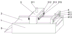
FIG. 1 is a schematic diagram of the overall structure of the present utility model;
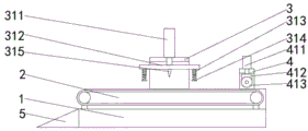
FIG. 2 is a cut-away view of the overall structure of the present utility model;
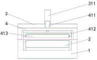
fig. 3 is a side view of the overall structure of the present utility model.
Wherein: 1. a main body; 2. a conveyor belt; 3. cutting the structure; 311. a first electric push rod; 312. a connecting plate; 313. an elastic structure; 314. briquetting; 315. a cutting knife; 4. an auxiliary structure; 411. a second electric push rod; 412. a lifting block; 413. a rotating roller; 5. and (5) landslide.
Description of the embodiments
The following description of the embodiments of the present utility model will be made clearly and completely with reference to the accompanying drawings, in which it is apparent that the embodiments described are only some embodiments of the present utility model, but not all embodiments. All other embodiments, which can be made by those skilled in the art based on the embodiments of the utility model without making any inventive effort, are intended to be within the scope of the utility model.
Referring to fig. 1-3, an embodiment 1, please refer to a cutting structure for preparing a composite fiber web, which comprises a main body 1, a conveying belt 2 is arranged on an inner plate at the lower end of the main body 1, a cutting structure 3 is fixedly connected to the outer surface of the upper end of the main body 1 near the middle, a first electric push rod 311 is arranged on the outer surface of the upper end of the cutting structure 3, a connecting plate 312 is fixedly connected to the outer surface of the lower end of the first electric push rod 311, an elastic structure 313 is arranged at the position of the outer surface of the lower end of the connecting plate 312 near the right side, a pressing block 314 is fixedly connected to the outer surface of the lower end of the elastic structure 313, a cutting knife 315 is arranged at the position of the outer surface of the lower end of the connecting plate 312 near the middle, an auxiliary structure 4 is fixedly connected to the outer surface of the upper end of the main body 1 near the right side, a second electric push rod 411 is arranged on the outer surface of the upper end of the auxiliary structure 4, a lifting block 412 is fixedly connected to the inner surface of the front end of the lifting block 412, a rotating roller 413 is rotatably connected to the outer surface of the left side of the main body 1, the elastic structure 313 is composed of a spring and a rod 313, the number of the elastic structure 313 is symmetrically distributed in a triangle shape, and the number of the two pressing blocks are symmetrically distributed, and the number of the two pressing blocks are 5.
The working principle is as follows; in the preparation stage, the worker adjusts the position of the rotary roller 413 through the second electric push rod 411 in cooperation with the lifting block 412, and then adjusts the distance between the rotary roller 413 and the conveyor belt 2, so that the device can be adjusted according to different thicknesses of different fiber webs, in the operation process of the device, the conveyor belt 2 drives the fiber web to move leftwards, meanwhile, when the fiber web reaches the position of the cutting structure 3, the first electric push rod 311 drives the connecting plate 312 to descend, so that the connecting plate 312 is driven to descend by the electric elastic structure 313, the pressing block 314 below the elastic structure 313 presses the fiber web firstly, then the fiber web is retracted along with the spring and the telescopic rod in the elastic structure 313, then the cutting knife 315 is cut close to the fiber web, after the fiber web is cut, the first electric push rod 311 drives other relevant components to ascend and be far away from the fiber web through the connecting plate 312, then the conveyor belt 2 drives the fiber web after the cutting is continuously moved leftwards until the fiber web slides out of the device from the landslide 5, and then the worker is uniformly collected again.
Although embodiments of the present utility model have been shown and described, it will be understood by those skilled in the art that various changes, modifications, substitutions and alterations can be made therein without departing from the principles and spirit of the utility model, the scope of which is defined in the appended claims and their equivalents.
Claims (6)
1. A composite web preparation cut structure comprising a main body (1), characterized in that: the utility model discloses a cutting device for the electric power machine, including main part (1), cutting structure (3), connecting plate (312), elastic structure (313), briquetting (314) are connected with to the position that main part (1) lower extreme inner panel is equipped with, the position that main part (1) upper end surface is close to the centre fixedly connected with cutting structure (3), cutting structure (3) upper end surface is equipped with first electric putter (311), first electric putter (311) lower extreme outer surface fixedly connected with connecting plate (312), the position that connecting plate (312) lower extreme surface is close to the right side is equipped with elastic structure (313), elastic structure (313) lower extreme outer surface fixedly connected with briquetting (314), the position that connecting plate (312) lower extreme surface is close to the centre is equipped with cutting knife (315).
2. A composite web preparation cut structure according to claim 1, wherein: the utility model discloses a self-adaptive intelligent control device for the automobile comprises a main body (1), wherein an auxiliary structure (4) is fixedly connected to the outer surface of the upper end of the main body (1) at a position close to the right side, a second electric push rod (411) is arranged on the outer surface of the upper end of the auxiliary structure (4), a lifting block (412) is fixedly connected to the outer surface of the lower end of the second electric push rod (411), a rotating roller (413) is rotatably connected to the inner surface of the front end of the lifting block (412), and a landslide (5) is fixedly connected to the outer surface of the left side of the main body (1).
3. A composite web preparation cut structure according to claim 1, wherein: the elastic structure (313) is composed of a spring and a damping rod.
4. A composite web preparation cut structure according to claim 1, wherein: the number of the elastic structures (313) is four, and the elastic structures are symmetrically distributed.
5. A composite web preparation cut structure according to claim 1, wherein: the number of the pressing blocks (314) is two, and the pressing blocks are symmetrically distributed.
6. A composite web preparation cut structure according to claim 2, wherein: the landslide (5) is triangular in shape.
Priority Applications (1)
| Application Number | Priority Date | Filing Date | Title |
|---|---|---|---|
| CN202320337595.4U CN219255742U (en) | 2023-02-28 | 2023-02-28 | Composite material fiber web preparation cutting structure |
Applications Claiming Priority (1)
| Application Number | Priority Date | Filing Date | Title |
|---|---|---|---|
| CN202320337595.4U CN219255742U (en) | 2023-02-28 | 2023-02-28 | Composite material fiber web preparation cutting structure |
Publications (1)
| Publication Number | Publication Date |
|---|---|
| CN219255742U true CN219255742U (en) | 2023-06-27 |
Family
ID=86873816
Family Applications (1)
| Application Number | Title | Priority Date | Filing Date |
|---|---|---|---|
| CN202320337595.4U Active CN219255742U (en) | 2023-02-28 | 2023-02-28 | Composite material fiber web preparation cutting structure |
Country Status (1)
| Country | Link |
|---|---|
| CN (1) | CN219255742U (en) |
-
2023
- 2023-02-28 CN CN202320337595.4U patent/CN219255742U/en active Active
Similar Documents
| Publication | Publication Date | Title |
|---|---|---|
| CN210551426U (en) | Equipment is cut to cotton coil stock of polyethylene bubble | |
| CN210256291U (en) | Cutting table with rapid cutting function | |
| CN118543768B (en) | Fixed-length shearing equipment and shearing method for electric wire | |
| CN222061271U (en) | Automatic laying mechanism for reinforcing glass fiber of wind power generation deflector | |
| CN108927858A (en) | A kind of fiberboard edge strip cutting mechanism | |
| CN216127377U (en) | Adjustable high-speed strip-dividing type strip-dividing device | |
| CN216155064U (en) | Carbon fiber fabric prepreg cutting device | |
| CN220994540U (en) | Rubber strip cutting device for rubber molding | |
| CN210282408U (en) | Batch film section device | |
| CN211141067U (en) | Automatic gauze piece slitting equipment | |
| CN209599501U (en) | A kind of four knife three pieces blank cutter of synchronization | |
| CN221873089U (en) | Novel efficient extrusion molding device | |
| CN221494430U (en) | Tool changing equipment of automatic strip separator of lithium battery | |
| CN216127345U (en) | Rope net cutting device | |
| CN223433674U (en) | A cutting device for backpack production | |
| CN219098238U (en) | Automatic reel changing device for winding | |
| CN222138949U (en) | Large glass strip opening device for pot cover manufacturing | |
| CN219819865U (en) | Glass fiber cutting device for fan blade processing | |
| CN223557367U (en) | A cutting device for manufacturing and processing luggage wheels | |
| CN220741407U (en) | Shearing mechanism is used in ground rice shaping | |
| CN221315121U (en) | Plastic uptake material cutting equipment | |
| CN218873915U (en) | Copper divides strip mechanism | |
| CN216940895U (en) | Polyurethane pipe material ejection of compact automatic cutout mechanism | |
| CN223029171U (en) | Cutting device for steel chain riveting processing | |
| CN220811317U (en) | Wire rope conveyer belt production line |
Legal Events
| Date | Code | Title | Description |
|---|---|---|---|
| GR01 | Patent grant | ||
| GR01 | Patent grant |