CN219254778U - Adjustable jig for machining - Google Patents
Adjustable jig for machining Download PDFInfo
- Publication number
- CN219254778U CN219254778U CN202223430131.2U CN202223430131U CN219254778U CN 219254778 U CN219254778 U CN 219254778U CN 202223430131 U CN202223430131 U CN 202223430131U CN 219254778 U CN219254778 U CN 219254778U
- Authority
- CN
- China
- Prior art keywords
- fixedly connected
- telescopic column
- jig
- sliding sleeve
- adjusting bolt
- Prior art date
- Legal status (The legal status is an assumption and is not a legal conclusion. Google has not performed a legal analysis and makes no representation as to the accuracy of the status listed.)
- Expired - Fee Related
Links
- 238000003754 machining Methods 0.000 title claims description 11
- 238000012545 processing Methods 0.000 claims abstract description 16
- 238000013461 design Methods 0.000 abstract description 4
- 230000008901 benefit Effects 0.000 abstract description 2
- 238000005516 engineering process Methods 0.000 abstract description 2
- 238000000034 method Methods 0.000 description 2
- 230000009286 beneficial effect Effects 0.000 description 1
- 230000008859 change Effects 0.000 description 1
- 238000004891 communication Methods 0.000 description 1
- 230000007547 defect Effects 0.000 description 1
- 238000010586 diagram Methods 0.000 description 1
- 238000009434 installation Methods 0.000 description 1
- 238000012986 modification Methods 0.000 description 1
- 230000004048 modification Effects 0.000 description 1
- 230000008569 process Effects 0.000 description 1
Images


Classifications
-
- Y—GENERAL TAGGING OF NEW TECHNOLOGICAL DEVELOPMENTS; GENERAL TAGGING OF CROSS-SECTIONAL TECHNOLOGIES SPANNING OVER SEVERAL SECTIONS OF THE IPC; TECHNICAL SUBJECTS COVERED BY FORMER USPC CROSS-REFERENCE ART COLLECTIONS [XRACs] AND DIGESTS
- Y02—TECHNOLOGIES OR APPLICATIONS FOR MITIGATION OR ADAPTATION AGAINST CLIMATE CHANGE
- Y02P—CLIMATE CHANGE MITIGATION TECHNOLOGIES IN THE PRODUCTION OR PROCESSING OF GOODS
- Y02P70/00—Climate change mitigation technologies in the production process for final industrial or consumer products
- Y02P70/10—Greenhouse gas [GHG] capture, material saving, heat recovery or other energy efficient measures, e.g. motor control, characterised by manufacturing processes, e.g. for rolling metal or metal working
Landscapes
- Machine Tool Units (AREA)
Abstract
本实用新型属于机械加工领域,尤其为一种用于机械加工的可调式冶具,包括桌板,桌板底部固定连接有支撑脚,桌板底部固定连接有连接座,连接座连接有调节螺栓,调节螺栓外围设置有弹簧,调节螺栓与弹簧顶部固定连接有内伸缩柱,内伸缩柱外围固定连接在桌板顶部有外伸缩柱,内伸缩柱顶部固定连接有连接块,连接块内部一侧固定连接有连接杆,连接杆表面滑动连接有滑套,滑套贯穿连接有紧固螺栓,滑套底部固定连接有固定架,固定架一端固定连接有切割机箱,切割机箱内部设置有切割刀片。本实用新型通过对机械加工冶具的改进,具有结构设计合理,采用可调节冶具位置的技术,从而有效地解决了现有机械加工冶具功能未完善不足的现状。
The utility model belongs to the field of mechanical processing, in particular to an adjustable jig for mechanical processing, comprising a table, the bottom of the table is fixedly connected with supporting feet, the bottom of the table is fixedly connected with a connecting seat, and the connecting seat is connected with an adjusting bolt. There is a spring on the periphery of the adjusting bolt, and an inner telescopic column is fixedly connected to the top of the adjusting bolt and the spring. The outer periphery of the inner telescopic column is fixedly connected to the top of the table. A connecting rod is connected, the surface of the connecting rod is slidably connected with a sliding sleeve, the sliding sleeve is connected with fastening bolts, the bottom of the sliding sleeve is fixedly connected with a fixing frame, one end of the fixing frame is fixedly connected with a cutting machine case, and a cutting blade is arranged inside the cutting machine case. The utility model has the advantages of reasonable structural design and the technology of adjusting the position of the jig through the improvement of the jig for mechanical processing, thereby effectively solving the current situation that the function of the jig for mechanical processing is not perfect.
Description
技术领域technical field
本实用新型涉及机械加工领域,尤其涉及一种用于机械加工的可调式冶具。The utility model relates to the field of machining, in particular to an adjustable jig for machining.
背景技术Background technique
冶具主要是作为协助控制位置或动作的一种工具,使用冶具的好处是如果是相同的制品,就算工人没有非常纯熟的技术,也可以迅速地借由冶具生产大量瑕疵少、变异性低的良品。所以就需要可调式的冶具。Jigs are mainly used as a tool to assist in controlling position or movement. The advantage of using jigs is that if the same product is used, even if the workers do not have very skilled skills, they can quickly use jigs to produce a large number of good products with few defects and low variability. . Therefore, adjustable jigs are needed.
目前现有的冶具虽然能够解决绝大部分的需求,但是使用时仍然会因为不够灵活使用,因此需要设计出一款用于机械加工的可调式冶具。Although the existing jigs can solve most of the needs, they are still not flexible enough to use. Therefore, it is necessary to design an adjustable jig for machining.
有鉴于此,针对现有的问题予以研究改良,提供一种用于机械加工的可调式冶具,具有结构设计合理,采用可调节冶具位置的技术,旨在通过该技术,达到解决问题与提高实用价值性的目的。In view of this, the existing problems are studied and improved, and an adjustable fixture for mechanical processing is provided, which has a reasonable structural design and adopts the technology of adjusting the position of the fixture. value purpose.
实用新型内容Utility model content
本实用新型的目的是为了解决现有技术中存在的缺点,而提出的一种用于机械加工的可调式冶具。The purpose of the utility model is to solve the shortcomings in the prior art, and propose an adjustable jig for mechanical processing.
为了实现上述目的,本实用新型采用了如下技术方案:包括桌板,所述桌板底部固定连接有支撑脚,所述桌板底部固定连接有连接座,所述连接座连接有调节螺栓,所述调节螺栓外围设置有弹簧,所述调节螺栓与弹簧顶部固定连接有内伸缩柱,所述内伸缩柱外围固定连接在桌板顶部有外伸缩柱,所述内伸缩柱顶部固定连接有连接块,所述连接块内部一侧固定连接有连接杆,所述连接杆表面滑动连接有滑套,所述滑套贯穿连接有紧固螺栓,所述滑套底部固定连接有固定架,所述固定架一端固定连接有切割机箱,所述切割机箱内部设置有电机,所述电机连接有转轴,所述转轴一端连接有切割刀片。In order to achieve the above object, the utility model adopts the following technical scheme: it includes a table board, the bottom of the table board is fixedly connected with supporting feet, the bottom of the table board is fixedly connected with a connecting seat, and the connecting seat is connected with an adjusting bolt, so A spring is arranged on the periphery of the adjustment bolt, and an inner telescopic column is fixedly connected to the top of the adjustment bolt and the spring. , the inner side of the connecting block is fixedly connected with a connecting rod, the surface of the connecting rod is slidably connected with a sliding sleeve, the sliding sleeve is connected with a fastening bolt, the bottom of the sliding sleeve is fixedly connected with a fixing frame, and the fixed One end of the frame is fixedly connected with a cutting box, and a motor is arranged inside the cutting box, and the motor is connected with a rotating shaft, and one end of the rotating shaft is connected with a cutting blade.
作为上述技术方案的进一步描述:As a further description of the above technical solution:
所述连接座设置在调节螺栓外围,所述调节螺栓数量为两个,所述调节螺栓之间为对称关系。The connecting seat is arranged on the periphery of the adjusting bolts, the number of the adjusting bolts is two, and the relationship between the adjusting bolts is symmetrical.
作为上述技术方案的进一步描述:As a further description of the above technical solution:
所述弹簧底部固定连接有连接座,所述弹簧顶部固定连接有内伸缩柱。The bottom of the spring is fixedly connected with a connecting seat, and the top of the spring is fixedly connected with an inner telescopic column.
作为上述技术方案的进一步描述:As a further description of the above technical solution:
所述内伸缩柱与外伸缩柱配套使用。The inner telescopic column is matched with the outer telescopic column.
作为上述技术方案的进一步描述:As a further description of the above technical solution:
所述连接块数量为两个,所述连接块之间为对称关系,所述连接杆固定在两个连接块之间。The number of the connecting blocks is two, the relationship between the connecting blocks is symmetrical, and the connecting rod is fixed between the two connecting blocks.
作为上述技术方案的进一步描述:As a further description of the above technical solution:
所述滑套数量为两个,所述滑套之间为对称关系,所述滑套设置有一个紧固螺栓。The number of the sliding sleeves is two, the relationship between the sliding sleeves is symmetrical, and the sliding sleeves are provided with a fastening bolt.
作为上述技术方案的进一步描述:As a further description of the above technical solution:
所述切割刀片与电机配套使用。The cutting blade is used in conjunction with a motor.
本实用新型具有如下有益效果:The utility model has the following beneficial effects:
现有的机械加工用冶具使用时虽然能够满足基本的使用需求,但是在需要一点变化的时候,因为其不可调节,因此使用时的全面性还不够,而本实用新型则设计出一款可调式机械加工用冶具,使冶具在不改变其原本使用的体验上,可以使其不仅在水平位置还可以在竖直位置上改变,使用起来更为的灵活,填补了现有可调式冶具的空缺。Although the existing jigs for mechanical processing can meet the basic needs of use, when a little change is needed, because they cannot be adjusted, the comprehensiveness of use is not enough, and the utility model designs an adjustable The jig for mechanical processing enables the jig to be changed not only in the horizontal position but also in the vertical position without changing its original use experience. It is more flexible to use and fills the vacancy of the existing adjustable jig.
附图说明Description of drawings
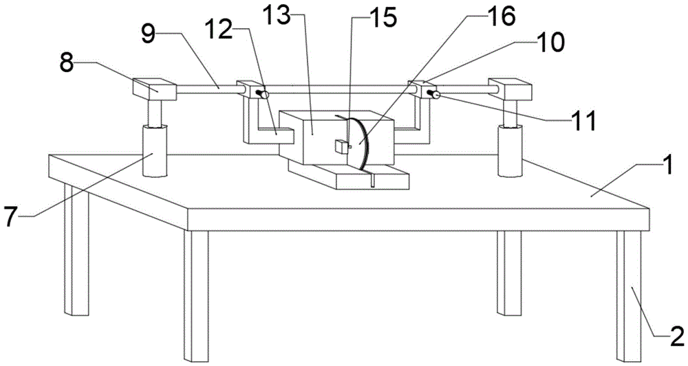
图1为本实用新型提出的一种用于机械加工的可调式冶具的立体结构图;Fig. 1 is a three-dimensional structure diagram of an adjustable jig for mechanical processing proposed by the utility model;
图2为本实用新型提出的一种用于机械加工的可调式冶具的正视图;Fig. 2 is a front view of an adjustable jig for mechanical processing proposed by the utility model;
图3为本实用新型提出的一种用于机械加工的可调式冶具的竖向剖面图;Fig. 3 is a vertical sectional view of an adjustable jig for mechanical processing proposed by the utility model;
图4为本实用新型提出的一种用于机械加工的可调式冶具调节螺栓处的竖向剖面图。Fig. 4 is a vertical section view of an adjustable jig adjusting bolt for mechanical processing proposed by the utility model.
图例说明:1、桌板;2、支撑脚;3、连接座;4、调节螺栓;5、弹簧;6、内伸缩柱;7、外伸缩柱;8、连接块;9、连接杆;10、滑套;11、紧固螺栓;12、固定架;13、切割机箱;14、电机;15、转轴;16、切割刀片。Legend: 1. Table board; 2. Support feet; 3. Connecting seat; 4. Adjusting bolt; 5. Spring; 6. Inner telescopic column; 7. Outer telescopic column; 8. Connecting block; 9. Connecting rod; 10 , sliding sleeve; 11, fastening bolt; 12, fixed frame; 13, cutting chassis; 14, motor; 15, rotating shaft; 16, cutting blade.
具体实施方式Detailed ways
下面将结合本实用新型实施例中的附图,对本实用新型实施例中的技术方案进行清楚、完整地描述,显然,所描述的实施例仅仅是本实用新型一部分实施例,而不是全部的实施例。基于本实用新型中的实施例,本领域普通技术人员在没有做出创造性劳动前提下所获得的所有其他实施例,都属于本实用新型保护的范围。The technical solutions in the embodiments of the present invention will be clearly and completely described below in conjunction with the accompanying drawings in the embodiments of the present invention. Obviously, the described embodiments are only part of the embodiments of the present invention, not all of them. example. Based on the embodiments of the present utility model, all other embodiments obtained by persons of ordinary skill in the art without making creative efforts belong to the scope of protection of the present utility model.
在本实用新型的描述中,需要说明的是,术语“中心”、“上”、“下”、“左”、“右”、“竖直”、“水平”、“内”、“外”等指示的方位或位置关系为基于附图所示的方位或位置关系,仅是为了便于描述本实用新型和简化描述,而不是指示或暗示所指的装置或元件必须具有特定的方位、以特定的方位构造和操作,因此不能理解为对本实用新型的限制;术语“第一”、“第二”、“第三”仅用于描述目的,而不能理解为指示或暗示相对重要性,此外,除非另有明确的规定和限定,术语“安装”、“相连”、“连接”应做广义理解,例如,可以是固定连接,也可以是可拆卸连接,或一体的连接;可以是机械连接,也可以是电连接;可以是直接相连,也可以通过中间媒介间接相连,可以是两个元件内部的连通。对于本领域的普通技术人员而言,可以具体情况理解上述术语在本实用新型中的具体含义。In the description of the present utility model, it should be noted that the terms "center", "upper", "lower", "left", "right", "vertical", "horizontal", "inner", "outer" The orientation or positional relationship indicated by etc. is based on the orientation or positional relationship shown in the drawings, which is only for the convenience of describing the utility model and simplifying the description, rather than indicating or implying that the device or element referred to must have a specific orientation, use a specific Therefore, it cannot be construed as a limitation on the present invention; the terms "first", "second", and "third" are only used for descriptive purposes, and cannot be interpreted as indicating or implying relative importance. In addition, Unless otherwise clearly specified and limited, the terms "installation", "connection" and "connection" should be understood in a broad sense, for example, it can be a fixed connection, a detachable connection, or an integral connection; it can be a mechanical connection, It can also be an electrical connection; it can be a direct connection, or an indirect connection through an intermediary, or an internal communication between two components. Those of ordinary skill in the art can understand the specific meanings of the above terms in the present invention in specific situations.
参照图1-4,一种用于机械加工的可调式冶具,包括桌板1,桌板1底部固定连接有支撑脚2,桌板1底部固定连接有连接座3,连接座3连接有调节螺栓4,调节螺栓4外围设置有弹簧5,调节螺栓4与弹簧5顶部固定连接有内伸缩柱6,内伸缩柱6外围固定连接在桌板1顶部有外伸缩柱7,内伸缩柱6顶部固定连接有连接块8,连接块8内部一侧固定连接有连接杆9,连接杆9表面滑动连接有滑套10,滑套10贯穿连接有紧固螺栓11,滑套10底部固定连接有固定架12,固定架12一端固定连接有切割机箱13,切割机箱13内部设置有电机14,电机14连接有转轴15,转轴15一端连接有切割刀片16。Referring to Figures 1-4, an adjustable jig for machining, including a table 1, the bottom of the table 1 is fixedly connected with a
具体的,连接座3设置在调节螺栓4外围,调节螺栓4数量为两个,调节螺栓4之间为对称关系,调节螺栓4借由连接座3进行连接。Specifically, the connecting
具体的,弹簧5底部固定连接有连接座3,弹簧5顶部固定连接有内伸缩柱6,弹簧5可以支撑内伸缩柱6,也可以限制内伸缩柱6。Specifically, the bottom of the
具体的,内伸缩柱6与外伸缩柱7配套使用,外伸缩柱7起到保护内伸缩柱6的作用。Specifically, the inner
具体的,连接块8数量为两个,连接块8之间为对称关系,连接杆9固定在两个连接块8之间,可以使切割机箱13进行水平移动。Specifically, there are two connecting
具体的,滑套10数量为两个,滑套10之间为对称关系,滑套10设置有一个紧固螺栓11,紧固螺栓11可以控制切割机箱13的移动与固定。Specifically, there are two
具体的,切割刀片16与电机14配套使用,可以进行机械加工。Specifically, the
工作原理及其流程:使用本实用新型时,可以根据需要进行机械加工的物体转动两个调节螺栓4,使得切割机箱13到达合适的高度,接着松开紧固螺栓11,使得滑套10带着切割机箱13进行水平移动直到到达合适的位置,接着扭紧紧固螺栓11,然后打开电机14,进行机械加工,加工完成后,将切割机箱13调整到原本的位置。Working principle and its process: when using the utility model, the two adjusting
最后应说明的是:以上所述仅为本实用新型的优选实施例而已,并不用于限制本实用新型,尽管参照前述实施例对本实用新型进行了详细的说明,对于本领域的技术人员来说,其依然可以对前述各实施例所记载的技术方案进行修改,或者对其中部分技术特征进行等同替换,凡在本实用新型的精神和原则之内,所作的任何修改、等同替换、改进等,均应包含在本实用新型的保护范围之内。Finally, it should be noted that: the above is only a preferred embodiment of the utility model, and is not intended to limit the utility model, although the utility model has been described in detail with reference to the foregoing embodiments, for those skilled in the art , it can still modify the technical solutions recorded in the foregoing embodiments, or perform equivalent replacements on some of the technical features. Any modifications, equivalent replacements, improvements, etc. made within the spirit and principles of the present utility model, All should be included within the protection scope of the present utility model.
Claims (7)
Priority Applications (1)
| Application Number | Priority Date | Filing Date | Title |
|---|---|---|---|
| CN202223430131.2U CN219254778U (en) | 2022-12-21 | 2022-12-21 | Adjustable jig for machining |
Applications Claiming Priority (1)
| Application Number | Priority Date | Filing Date | Title |
|---|---|---|---|
| CN202223430131.2U CN219254778U (en) | 2022-12-21 | 2022-12-21 | Adjustable jig for machining |
Publications (1)
| Publication Number | Publication Date |
|---|---|
| CN219254778U true CN219254778U (en) | 2023-06-27 |
Family
ID=86864101
Family Applications (1)
| Application Number | Title | Priority Date | Filing Date |
|---|---|---|---|
| CN202223430131.2U Expired - Fee Related CN219254778U (en) | 2022-12-21 | 2022-12-21 | Adjustable jig for machining |
Country Status (1)
| Country | Link |
|---|---|
| CN (1) | CN219254778U (en) |
-
2022
- 2022-12-21 CN CN202223430131.2U patent/CN219254778U/en not_active Expired - Fee Related
Similar Documents
| Publication | Publication Date | Title |
|---|---|---|
| CN219464777U (en) | A tool holder assembly for a numerically controlled lathe | |
| CN211522640U (en) | Cutting machine for shirt fabric | |
| CN216781009U (en) | But height-adjusting's machine tool | |
| CN214025894U (en) | Production of mobile phone motherboard upper cover is with tailorring device | |
| CN211071955U (en) | Milling machine that facilitates use | |
| CN207406020U (en) | A kind of space bar member positioner in construction | |
| CN213904718U (en) | Model connection structure for architectural design | |
| CN107639357A (en) | A kind of fixture for being used to clamp trousers | |
| CN222751647U (en) | Double-deck scalable outdoor table | |
| CN221792939U (en) | Auxiliary fixing mechanism for cutting machine | |
| CN207723550U (en) | A kind of equipment of processing miniature workpiece | |
| CN221967338U (en) | A punching device for back plate of power distribution cabinet | |
| CN210731441U (en) | Welding device for high-chromium alloy | |
| CN218225510U (en) | An adjustable fixing device for mold steel | |
| CN223368906U (en) | Multi-station combination machine | |
| CN208556702U (en) | A kind of three coordinate mobile platforms | |
| CN205764933U (en) | Column of five-axis linkage CNC machining center | |
| CN216731378U (en) | Workstation is used in sculpture design manufacturing | |
| CN219307158U (en) | Production feeding positioning device of paper diaper | |
| CN221583549U (en) | Multifunctional construction machine capable of quickly replacing templates | |
| CN205647101U (en) | Carving mills motor fixing structure of machine | |
| CN218426881U (en) | Automatic compensation device for sawing error of part | |
| CN223776648U (en) | Hinge locating hole tool for manufacturing engine cylinder body | |
| CN215241045U (en) | Compound cutting device of paper products intelligence | |
| CN219598558U (en) | Turbine shell welding tool |
Legal Events
| Date | Code | Title | Description |
|---|---|---|---|
| GR01 | Patent grant | ||
| GR01 | Patent grant | ||
| CF01 | Termination of patent right due to non-payment of annual fee | ||
| CF01 | Termination of patent right due to non-payment of annual fee |
Granted publication date: 20230627 |