CN219254229U - Clamping equipment for aluminum product processing and punching - Google Patents
Clamping equipment for aluminum product processing and punching Download PDFInfo
- Publication number
- CN219254229U CN219254229U CN202223485305.5U CN202223485305U CN219254229U CN 219254229 U CN219254229 U CN 219254229U CN 202223485305 U CN202223485305 U CN 202223485305U CN 219254229 U CN219254229 U CN 219254229U
- Authority
- CN
- China
- Prior art keywords
- plate
- wall
- supporting
- aluminum
- fixedly connected
- Prior art date
- Legal status (The legal status is an assumption and is not a legal conclusion. Google has not performed a legal analysis and makes no representation as to the accuracy of the status listed.)
- Expired - Fee Related
Links
- XAGFODPZIPBFFR-UHFFFAOYSA-N aluminium Chemical compound [Al] XAGFODPZIPBFFR-UHFFFAOYSA-N 0.000 title claims abstract description 77
- 229910052782 aluminium Inorganic materials 0.000 title claims abstract description 76
- 238000004080 punching Methods 0.000 title claims abstract description 35
- 238000012545 processing Methods 0.000 title claims abstract description 22
- 230000007246 mechanism Effects 0.000 claims abstract description 17
- 238000005553 drilling Methods 0.000 claims description 13
- 239000011148 porous material Substances 0.000 claims 4
- 239000000463 material Substances 0.000 abstract description 23
- 238000010586 diagram Methods 0.000 description 4
- 238000000034 method Methods 0.000 description 4
- 230000009286 beneficial effect Effects 0.000 description 3
- 230000005540 biological transmission Effects 0.000 description 3
- 230000008569 process Effects 0.000 description 3
- 229910000838 Al alloy Inorganic materials 0.000 description 2
- 230000009471 action Effects 0.000 description 2
- 238000004519 manufacturing process Methods 0.000 description 2
- 238000012986 modification Methods 0.000 description 2
- 230000004048 modification Effects 0.000 description 2
- 230000001681 protective effect Effects 0.000 description 2
- 238000005275 alloying Methods 0.000 description 1
- 238000005452 bending Methods 0.000 description 1
- 238000005266 casting Methods 0.000 description 1
- 238000004040 coloring Methods 0.000 description 1
- 230000007812 deficiency Effects 0.000 description 1
- 238000013461 design Methods 0.000 description 1
- 239000011888 foil Substances 0.000 description 1
- 238000005242 forging Methods 0.000 description 1
- 238000011160 research Methods 0.000 description 1
- 125000006850 spacer group Chemical group 0.000 description 1
- 230000001360 synchronised effect Effects 0.000 description 1
Images


Classifications
-
- Y—GENERAL TAGGING OF NEW TECHNOLOGICAL DEVELOPMENTS; GENERAL TAGGING OF CROSS-SECTIONAL TECHNOLOGIES SPANNING OVER SEVERAL SECTIONS OF THE IPC; TECHNICAL SUBJECTS COVERED BY FORMER USPC CROSS-REFERENCE ART COLLECTIONS [XRACs] AND DIGESTS
- Y02—TECHNOLOGIES OR APPLICATIONS FOR MITIGATION OR ADAPTATION AGAINST CLIMATE CHANGE
- Y02P—CLIMATE CHANGE MITIGATION TECHNOLOGIES IN THE PRODUCTION OR PROCESSING OF GOODS
- Y02P70/00—Climate change mitigation technologies in the production process for final industrial or consumer products
- Y02P70/10—Greenhouse gas [GHG] capture, material saving, heat recovery or other energy efficient measures, e.g. motor control, characterised by manufacturing processes, e.g. for rolling metal or metal working
Landscapes
- Perforating, Stamping-Out Or Severing By Means Other Than Cutting (AREA)
Abstract
本实用新型公开了一种铝材加工打孔用夹持设备,包括支撑框架和设置在支撑框架内部的支撑机构,所述支撑机构包括第一支撑组件、连接组件和第二支撑组件;该铝材加工打孔用夹持设备,与现有的普通铝材加工打孔用夹持设备相比,本实用新型通过设置第一支撑板和第二支撑板,升降块滑动带动第一升降板外壁的第一支撑板与铝材主体的内壁相贴合,与此同时,第一升降板滑动通过主动孔板带动旋转杆转动,旋转杆转动通过从动孔板带动第二升降板外壁的第二支撑板与铝材主体的内壁相贴合,通过第一支撑板和第二支撑板的相对滑动,实现对铝材主体的加工支撑操作,避免铝材主体在打孔时发生形变。
The utility model discloses a clamping device for processing and punching aluminum materials, which comprises a supporting frame and a supporting mechanism arranged inside the supporting frame, and the supporting mechanism includes a first supporting component, a connecting component and a second supporting component; the aluminum Compared with the existing clamping equipment for processing and punching ordinary aluminum materials, the utility model sets the first support plate and the second support plate, and the lifting block slides to drive the outer wall of the first lifting plate At the same time, the first lifting plate slides through the active orifice plate to drive the rotating rod to rotate, and the rotating rod rotates to drive the second lifting plate on the outer wall of the second lifting plate through the driven orifice plate. The support plate is attached to the inner wall of the aluminum body, and through the relative sliding of the first support plate and the second support plate, the processing and supporting operation of the aluminum body is realized to avoid deformation of the aluminum body when punching holes.
Description
技术领域technical field
本实用新型涉及铝材打孔技术领域,具体为一种铝材加工打孔用夹持设备。The utility model relates to the technical field of aluminum material punching, in particular to a clamping device for aluminum material processing and punching.
背景技术Background technique
铝材由铝和其它合金元素制造的制品。通常是先加工成铸造品、锻造品以及箔、板、带、管、棒、型材等后,再经冷弯、锯切、钻孔、拼装、上色等工序而制成,铝和铝合金易于加工成各种形状,能适应各种连接工艺,在铝材加工时,有时需要对铝材进行打孔。Aluminum products made of aluminum and other alloying elements. It is usually processed into castings, forgings, foils, plates, strips, tubes, rods, profiles, etc., and then processed by cold bending, sawing, drilling, assembling, and coloring. Aluminum and aluminum alloys It is easy to process into various shapes, and can adapt to various connection processes. When aluminum materials are processed, it is sometimes necessary to punch holes in the aluminum materials.
如申请号为CN213888230U,本实用新型涉及铝材加工设备技术领域,具体是一种铝材生产用打孔设备,包括底座,所述底座左右两端顶部均固定连接设置有支撑板,两侧所述支撑板之间设置有钻孔机构,所述钻孔机构下侧设置有夹紧机构,所述夹紧机构与钻孔机构之间设置有传动机构,本实用新型,通过设置钻孔机构,利用伸缩杆和第二电机可以对钻机的位置进行调节,利于提高装置钻孔的精确度,通过设置夹紧机构,夹板在弹簧的作用下可以对铝材进行固定,保证钻孔过程中的稳定性,通过设置传动机构,利用电机对滑块的高度进行调节,滑块通过连接杆带动推板移动,推板与传动齿轮作用使连接板向内挤压弹簧,从而使铝材能被固定的更加牢固,保证打孔精度。For example, the application number is CN213888230U. The utility model relates to the technical field of aluminum material processing equipment, specifically a kind of punching equipment for aluminum material production, including a base. A drilling mechanism is arranged between the support plates, a clamping mechanism is arranged on the lower side of the drilling mechanism, and a transmission mechanism is arranged between the clamping mechanism and the drilling mechanism. In the utility model, by setting the drilling mechanism, The position of the drilling rig can be adjusted by using the telescopic rod and the second motor, which is beneficial to improve the drilling accuracy of the device. By setting the clamping mechanism, the splint can fix the aluminum material under the action of the spring to ensure the stability during the drilling process. By setting the transmission mechanism and using the motor to adjust the height of the slider, the slider drives the push plate to move through the connecting rod, and the action of the push plate and the transmission gear makes the connecting plate squeeze the spring inward, so that the aluminum material can be fixed It is more firm and ensures the drilling accuracy.
但是该铝材生产用打孔设备,在使用时,打孔钻头在进行打孔时需要向下挤压铝材,有些较薄的铝材会因此发生凹陷,导致打孔直径变大,以及,现有的铝材会直接夹持表面,导致铝材表面受损。However, when using the punching equipment for aluminum production, the punching drill bit needs to squeeze the aluminum material downwards when punching holes, and some thinner aluminum materials will be dented as a result, resulting in a larger hole diameter, and, Existing aluminum will grip the surface directly, causing damage to the aluminum surface.
于是,有鉴于此,针对现有的结构不足予以研究改良,提出一种铝材加工打孔用夹持设备。Therefore, in view of this, research and improvements are made to address the existing structural deficiencies, and a clamping device for aluminum processing and punching is proposed.
实用新型内容Utility model content
本实用新型的目的在于提供一种铝材加工打孔用夹持设备,以解决上述背景技术中提出的较薄的铝材会因此发生凹陷和铝材表面受损问题。The purpose of this utility model is to provide a clamping device for processing and punching aluminum materials, so as to solve the problems that the thinner aluminum materials will be dented and the surface of the aluminum materials will be damaged.
为实现上述目的,本实用新型提供如下技术方案:一种铝材加工打孔用夹持设备,包括支撑框架和设置在支撑框架内部的支撑机构,所述支撑机构包括第一支撑组件、连接组件和第二支撑组件;In order to achieve the above purpose, the utility model provides the following technical solutions: a clamping device for aluminum material processing and punching, including a support frame and a support mechanism arranged inside the support frame, the support mechanism includes a first support assembly, a connecting assembly and a second support assembly;
所述第一支撑组件包括气动推杆、升降块、第一升降板和第一支撑板,所述支撑框架的内壁固定连接有气动推杆,所述气动推杆的输出端安装有升降块,所述升降块的侧壁固定连接有第一升降板,所述第一升降板的外壁延伸至支撑框架的外壁固定连接有第一支撑板;The first support assembly includes a pneumatic push rod, a lifting block, a first lifting plate and a first support plate, the inner wall of the support frame is fixedly connected with a pneumatic push rod, and the output end of the pneumatic push rod is equipped with a lifting block, The side wall of the lifting block is fixedly connected with a first lifting plate, and the outer wall of the first lifting plate extends to the outer wall of the supporting frame and is fixedly connected with a first supporting plate;
所述连接组件包括主动孔板和旋转杆,所述第一升降板的顶端固定连接有主动孔板,所述主动孔板的外壁活动连接有与支撑框架内壁旋接的旋转杆;The connecting assembly includes an active orifice and a rotating rod, the top of the first lifting plate is fixedly connected with an active orifice, and the outer wall of the active orifice is movably connected with a rotating rod that is screwed to the inner wall of the support frame;
所述第二支撑组件包括从动孔板、第二升降板、第二支撑板和铝材主体,所述旋转杆的顶端活动连接有从动孔板,所述从动孔板的顶端固定连接有第二升降板,所述第二升降板的外壁延伸至支撑框架的外壁固定连接有第二支撑板,所述第二支撑板的外壁贴合有与第一支撑板外相贴合的铝材主体。The second support assembly includes a driven orifice plate, a second lifting plate, a second support plate and an aluminum body. The top end of the rotating rod is movably connected to a driven orifice plate, and the top end of the driven orifice plate is fixedly connected to There is a second lifting plate, the outer wall of the second lifting plate extends to the outer wall of the supporting frame and is fixedly connected with a second supporting plate, and the outer wall of the second supporting plate is bonded with an aluminum material that is bonded to the outer surface of the first supporting plate main body.
优选的,所述支撑框架的底端固定连接有定位框架,所述定位框架的内壁贯穿有螺纹杆,所述螺纹杆的一端固定连接有手轮,所述螺纹杆的外壁螺纹连接有螺纹滑块,所述螺纹滑块的外壁旋接有连接杆,所述连接杆的一端旋接有与定位框架内壁滑动连接的伸缩板,所述伸缩板与定位框架的连接部位开设有限位滑槽,所述伸缩板的顶端延伸至定位框架的上方固定连接有定位夹板,所述定位夹板的外壁固定连接有与铝材主体外壁相贴合的垫片,所述支撑框架的顶端固定连接有支架,所述支架的外壁固定连接有液压推杆,所述液压推杆的输出端固定连接有与支架外壁滑动连接的打孔电机,所述打孔电机的输出端位于铝材主体的上方安装有打孔钻头。Preferably, the bottom end of the support frame is fixedly connected with a positioning frame, the inner wall of the positioning frame is penetrated with a threaded rod, one end of the threaded rod is fixedly connected with a hand wheel, and the outer wall of the threaded rod is threaded with a threaded slider. block, the outer wall of the threaded slider is screwed with a connecting rod, and one end of the connecting rod is screwed with a telescopic plate slidingly connected with the inner wall of the positioning frame, and a limited chute is provided at the connection part between the telescopic plate and the positioning frame, The top of the expansion plate extends to the top of the positioning frame and is fixedly connected with a positioning splint, the outer wall of the positioning splint is fixedly connected with a gasket that fits the outer wall of the aluminum body, and the top of the support frame is fixedly connected with a bracket. The outer wall of the bracket is fixedly connected with a hydraulic push rod, and the output end of the hydraulic push rod is fixedly connected with a punching motor slidingly connected with the outer wall of the bracket. hole drill.
优选的,所述第一支撑板通过升降块和第一升降板与铝材主体之间构成伸缩结构,所述第一升降板与第二升降板相平行。Preferably, the first support plate forms a telescopic structure through the lifting block and between the first lifting plate and the aluminum body, and the first lifting plate is parallel to the second lifting plate.
优选的,所述旋转杆通过第一升降板和主动孔板与支撑框架之间构成旋转结构。Preferably, the rotating rod forms a rotating structure between the first lifting plate and the active orifice plate and the support frame.
优选的,所述第二升降板通过旋转杆和从动孔板与支撑框架之间构成滑动结构,所述第二支撑板通过第二升降板与铝材主体之间构成伸缩结构。Preferably, the second lifting plate forms a sliding structure between the rotating rod and the driven orifice plate and the supporting frame, and the second supporting plate forms a telescopic structure between the second lifting plate and the aluminum body.
优选的,所述连接杆设置与两组,两组所述连接杆的位置关系关于螺纹滑块相对称。Preferably, the connecting rods are arranged in two groups, and the positional relationship of the connecting rods in the two groups is symmetrical with respect to the threaded slider.
优选的,所述伸缩板通过螺纹滑块和连接杆与限位滑槽之间构成滑动结构。Preferably, the telescopic plate forms a sliding structure between the threaded slider and the connecting rod and the limiting chute.
与现有技术相比,本实用新型的有益效果是:Compared with the prior art, the beneficial effects of the utility model are:
1.本实用新型通过设置第一支撑板和第二支撑板,升降块滑动带动第一升降板外壁的第一支撑板与铝材主体的内壁相贴合,与此同时,第一升降板滑动通过主动孔板带动旋转杆转动,旋转杆转动通过从动孔板带动第二升降板外壁的第二支撑板与铝材主体的内壁相贴合,通过第一支撑板和第二支撑板的相对滑动,实现对铝材主体的加工支撑操作,避免铝材主体在打孔时发生形变。1. The utility model sets the first support plate and the second support plate, and the lifting block slides to drive the first support plate on the outer wall of the first lifting plate to fit the inner wall of the aluminum body. At the same time, the first lifting plate slides The rotation of the rotating rod is driven by the active orifice plate, and the rotation of the rotating rod drives the second support plate on the outer wall of the second lifting plate through the driven orifice to fit the inner wall of the aluminum body, and through the relative relationship between the first support plate and the second support plate Sliding to realize the processing and supporting operation of the aluminum body and avoid deformation of the aluminum body when punching holes.
2.本实用新型通过设置定位夹板和垫片,螺纹滑块滑动带动两组连接杆同步运动,以使得螺纹滑块滑动通过连接杆带动伸缩板沿限位滑槽的外壁滑动,伸缩板滑动带动定位夹板外壁的垫片与铝材主体相贴合,通过设置垫片,实现对铝材主体定位的防护操作。2. The utility model is provided with positioning splints and gaskets, and the threaded slider slides to drive the two sets of connecting rods to move synchronously, so that the threaded slider slides through the connecting rods to drive the telescopic plate to slide along the outer wall of the limit chute, and the telescopic plate slides to drive The gasket on the outer wall of the positioning splint is fitted to the aluminum body, and the protective operation of the positioning of the aluminum body is realized by setting the gasket.
附图说明Description of drawings
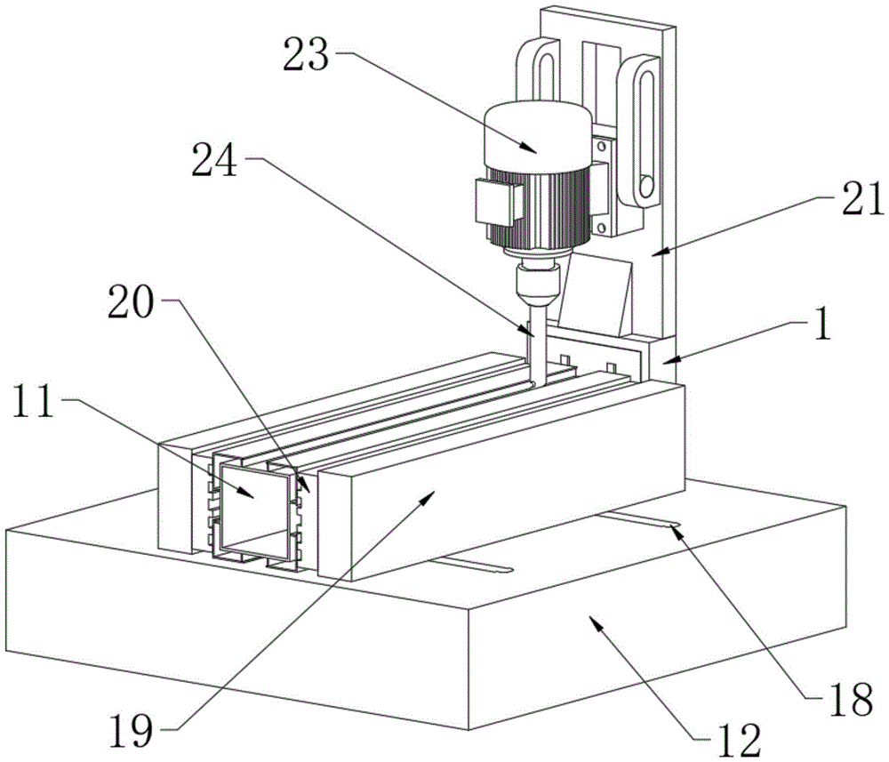
图1为本实用新型的整体第一视角结构示意图;Fig. 1 is a structural schematic diagram of the overall first viewing angle of the utility model;
图2为本实用新型的整体第二视角结构示意图;Fig. 2 is a structural schematic diagram of the overall second viewing angle of the utility model;
图3为本实用新型的第一支撑板和第二支撑板结构示意图;Fig. 3 is a structural schematic diagram of a first support plate and a second support plate of the present invention;
图4为本实用新型的定位夹板连接结构示意图。Fig. 4 is a schematic diagram of the connection structure of the positioning splint of the present invention.
图中:1、支撑框架;2、气动推杆;3、升降块;4、第一升降板;5、第一支撑板;6、主动孔板;7、旋转杆;8、从动孔板;9、第二升降板;10、第二支撑板;11、铝材主体;12、定位框架;13、螺纹杆;14、手轮;15、螺纹滑块;16、连接杆;17、伸缩板;18、限位滑槽;19、定位夹板;20、垫片;21、支架;22、液压推杆;23、打孔电机;24、打孔钻头。In the figure: 1. Support frame; 2. Pneumatic push rod; 3. Lifting block; 4. First lifting plate; 5. First supporting plate; 6. Active orifice plate; 7. Rotating rod; 8. Driven orifice plate ; 9, the second lifting plate; 10, the second support plate; 11, the main body of aluminum; 12, the positioning frame; 13, the threaded rod; 14, the hand wheel; 15, the threaded slider; 18, limit chute; 19, positioning splint; 20, spacer; 21, bracket; 22, hydraulic push rod; 23, punching motor; 24, punching drill.
具体实施方式Detailed ways
下面将结合本实用新型实施例中的附图,对本实用新型实施例中的技术方案进行清楚、完整地描述,显然,所描述的实施例仅仅是本实用新型一部分实施例,而不是全部的实施例。基于本实用新型中的实施例,本领域普通技术人员在没有做出创造性劳动前提下所获得的所有其他实施例,都属于本实用新型保护的范围。The technical solutions in the embodiments of the present invention will be clearly and completely described below in conjunction with the accompanying drawings in the embodiments of the present invention. Obviously, the described embodiments are only part of the embodiments of the present invention, not all of them. example. Based on the embodiments of the present utility model, all other embodiments obtained by persons of ordinary skill in the art without making creative efforts belong to the scope of protection of the present utility model.
实施例1Example 1
如图1-3所示,图示中的一种铝材加工打孔用夹持设备,包括支撑框架1和设置在支撑框架1内部的支撑机构,支撑机构包括第一支撑组件、连接组件和第二支撑组件;As shown in Figures 1-3, a clamping device for processing and punching aluminum materials in the illustration includes a
第一支撑组件包括气动推杆2、升降块3、第一升降板4和第一支撑板5,支撑框架1的内壁固定连接有气动推杆2,气动推杆2的输出端安装有升降块3,升降块3的侧壁固定连接有第一升降板4,第一升降板4的外壁延伸至支撑框架1的外壁固定连接有第一支撑板5;The first support assembly includes a pneumatic push rod 2, a
连接组件包括主动孔板6和旋转杆7,第一升降板4的顶端固定连接有主动孔板6,主动孔板6的外壁活动连接有与支撑框架1内壁旋接的旋转杆7;The connecting assembly includes an
第二支撑组件包括从动孔板8、第二升降板9、第二支撑板10和铝材主体11,旋转杆7的顶端活动连接有从动孔板8,从动孔板8的顶端固定连接有第二升降板9,第二升降板9的外壁延伸至支撑框架1的外壁固定连接有第二支撑板10,第二支撑板10的外壁贴合有与第一支撑板5外相贴合的铝材主体11。The second support assembly includes a driven
其中,如图3所示,第一支撑板5通过升降块3和第一升降板4与铝材主体11之间构成伸缩结构,第一升降板4与第二升降板9相平行,有利于升降块3滑动带动第一升降板4外壁的第一支撑板5与铝材主体11的内壁相贴合,实现对第一支撑板5滑动的控制操作。Wherein, as shown in Figure 3, the
其中,如图3所示,旋转杆7通过第一升降板4和主动孔板6与支撑框架1之间构成旋转结构,有利于第一升降板4滑动通过主动孔板6带动旋转杆7转动,实现对旋转杆7转动的控制操作。Wherein, as shown in Figure 3, the
其中,如图3所示,第二升降板9通过旋转杆7和从动孔板8与支撑框架1之间构成滑动结构,第二支撑板10通过第二升降板9与铝材主体11之间构成伸缩结构,有利于旋转杆7转动通过从动孔板8带动第二升降板9外壁的第二支撑板10与铝材主体11的内壁相贴合,通过第一支撑板5和第二支撑板10的相对滑动,实现对铝材主体11的加工支撑操作。Wherein, as shown in Figure 3, the
实施例2Example 2
如图1、图2和图4所示,本实施方式对实施例1进一步说明,支撑框架1的底端固定连接有定位框架12,定位框架12的内壁贯穿有螺纹杆13,螺纹杆13的一端固定连接有手轮14,螺纹杆13的外壁螺纹连接有螺纹滑块15,螺纹滑块15的外壁旋接有连接杆16,连接杆16的一端旋接有与定位框架12内壁滑动连接的伸缩板17,伸缩板17与定位框架12的连接部位开设有限位滑槽18,伸缩板17的顶端延伸至定位框架12的上方固定连接有定位夹板19,定位夹板19的外壁固定连接有与铝材主体11外壁相贴合的垫片20,支撑框架1的顶端固定连接有支架21,支架21的外壁固定连接有液压推杆22,液压推杆22的输出端固定连接有与支架21外壁滑动连接的打孔电机23,打孔电机23的输出端位于铝材主体11的上方安装有打孔钻头24,有利于手轮14转动通过螺纹杆13带动螺纹滑块15滑动,螺纹滑块15滑动带动两组连接杆16同步运动,以使得螺纹滑块15滑动通过连接杆16带动伸缩板17沿限位滑槽18的外壁滑动,伸缩板17滑动带动定位夹板19外壁的垫片20与铝材主体11相贴合,通过设置垫片20,实现对铝材主体11定位的防护操作,然后,液压推杆22工作带动打孔电机23沿支架21的外壁滑动,然后打孔电机23工作带动打孔钻头24转动,对铝材主体11进行打孔操作。As shown in Fig. 1, Fig. 2 and Fig. 4, the present embodiment further illustrates
其中,如图4所示,连接杆16设置与两组,两组连接杆16的位置关系关于螺纹滑块15相对称,通过设置两组连接杆16,有利于手轮14转动通过螺纹杆13带动螺纹滑块15滑动,螺纹滑块15滑动带动两组连接杆16同步运动,实现对两组连接杆16同步运动的控制操作。Wherein, as shown in Figure 4, connecting
其中,如图4所示,伸缩板17通过螺纹滑块15和连接杆16与限位滑槽18之间构成滑动结构,有利于螺纹滑块15滑动通过连接杆16带动伸缩板17沿限位滑槽18的外壁滑动,伸缩板17滑动带动定位夹板19外壁的垫片20与铝材主体11相贴合,通过两组定位夹板19的相对滑动,实现对铝材主体11定位夹紧操作。Wherein, as shown in Figure 4, the
工作原理:在使用该铝材加工打孔用夹持设备时,首先,对铝材主体11进行夹持定位操作,在定位框架12中,加工人员转动手轮14,手轮14转动通过螺纹杆13带动螺纹滑块15滑动,螺纹滑块15滑动带动两组连接杆16同步运动,以使得螺纹滑块15滑动通过连接杆16带动伸缩板17沿限位滑槽18的外壁滑动,伸缩板17滑动带动定位夹板19外壁的垫片20与铝材主体11相贴合,通过设置垫片20,实现对铝材主体11定位的防护操作。Working principle: When using the clamping equipment for aluminum processing and punching, firstly, the aluminum
接着,对铝材主体11进行加工支撑操作,在支撑框架1中,气动推杆2工作带动升降块3沿支撑框架1的内壁滑动,升降块3滑动带动第一升降板4外壁的第一支撑板5与铝材主体11的内壁相贴合,与此同时,第一升降板4滑动通过主动孔板6带动旋转杆7转动,旋转杆7转动通过从动孔板8带动第二升降板9外壁的第二支撑板10与铝材主体11的内壁相贴合,通过第一支撑板5和第二支撑板10的相对滑动,实现对铝材主体11的加工支撑操作,避免铝材主体11在打孔时发生形变。Next, the
最后,液压推杆22工作带动打孔电机23沿支架21的外壁滑动,然后打孔电机23工作带动打孔钻头24转动,对铝材主体11进行打孔操作,这就是该铝材加工打孔用夹持设备的工作原理。Finally, the
本实用新型的实施例是为了示例和描述起见而给出的,而并不是无遗漏的或者将本实用新型限于所公开的形式。很多修改和变化对于本领域的普通技术人员而言是显而易见的。选择和描述实施例是为了更好说明本实用新型的原理和实际应用,并且使本领域的普通技术人员能够理解本实用新型从而设计适于特定用途的带有各种修改的各种实施例。The embodiments of the invention have been presented for purposes of illustration and description, but are not intended to be exhaustive or to limit the invention to the forms disclosed. Many modifications and changes will be apparent to those of ordinary skill in the art. The embodiment was chosen and described in order to better explain the principle and practical application of the invention, and to enable those of ordinary skill in the art to understand the invention and design various embodiments with various modifications suitable for particular purposes.
Claims (7)
Priority Applications (1)
| Application Number | Priority Date | Filing Date | Title |
|---|---|---|---|
| CN202223485305.5U CN219254229U (en) | 2022-12-27 | 2022-12-27 | Clamping equipment for aluminum product processing and punching |
Applications Claiming Priority (1)
| Application Number | Priority Date | Filing Date | Title |
|---|---|---|---|
| CN202223485305.5U CN219254229U (en) | 2022-12-27 | 2022-12-27 | Clamping equipment for aluminum product processing and punching |
Publications (1)
| Publication Number | Publication Date |
|---|---|
| CN219254229U true CN219254229U (en) | 2023-06-27 |
Family
ID=86862411
Family Applications (1)
| Application Number | Title | Priority Date | Filing Date |
|---|---|---|---|
| CN202223485305.5U Expired - Fee Related CN219254229U (en) | 2022-12-27 | 2022-12-27 | Clamping equipment for aluminum product processing and punching |
Country Status (1)
| Country | Link |
|---|---|
| CN (1) | CN219254229U (en) |
-
2022
- 2022-12-27 CN CN202223485305.5U patent/CN219254229U/en not_active Expired - Fee Related
Similar Documents
| Publication | Publication Date | Title |
|---|---|---|
| CN209986266U (en) | Drilling equipment is used in pipeline installation | |
| CN214053196U (en) | Positioning device for bending machine | |
| CN210877921U (en) | Numerical control gear shaping machine | |
| CN212043263U (en) | Square-round integrated vertical straight seam welding equipment | |
| CN204639258U (en) | Double Milling Digit Control Machine Tool | |
| CN214264119U (en) | Accurate cutting device is used in indicator tablet preparation | |
| CN220178536U (en) | Deck welding positioning mechanism | |
| CN112058959A (en) | Metal plate bending equipment for machining | |
| CN217912415U (en) | Hydraulic cutting perforating device | |
| CN215279378U (en) | Stamping device is used in aluminum product processing | |
| CN216606942U (en) | Riveting machine for stainless steel tableware handle | |
| CN211071391U (en) | High-precision pipe bending machine for producing automobile lower bent beam assembly | |
| CN213764499U (en) | Shearing device for medium plate processing | |
| CN219004769U (en) | Positioning device convenient to use for aluminum product processing | |
| CN223199282U (en) | A cement board punching machine for municipal engineering | |
| WO2019090632A1 (en) | Efficient and precise wood board boring device | |
| CN209319936U (en) | An automatic punching machine for plastic profiles | |
| CN218835731U (en) | Stamping device for metal product | |
| CN218574799U (en) | Positioning tool for punch | |
| CN214719607U (en) | Special bracket for numerical control bending machine | |
| CN223543797U (en) | An adjustable angle metal sheet bending machine | |
| CN218311491U (en) | A kind of cutting equipment for sheet metal parts used in the production of external racks of CNC machine tools | |
| CN217254723U (en) | Vertical engraver press device | |
| CN218517571U (en) | Stamping device is used in aluminum product processing | |
| CN220942563U (en) | Positioning tool for nonferrous metal rolled piece |
Legal Events
| Date | Code | Title | Description |
|---|---|---|---|
| GR01 | Patent grant | ||
| GR01 | Patent grant | ||
| CF01 | Termination of patent right due to non-payment of annual fee | ||
| CF01 | Termination of patent right due to non-payment of annual fee |
Granted publication date: 20230627 |