CN219253794U - Punching machine is used in keyboard bottom plate production - Google Patents
Punching machine is used in keyboard bottom plate production Download PDFInfo
- Publication number
- CN219253794U CN219253794U CN202320176715.7U CN202320176715U CN219253794U CN 219253794 U CN219253794 U CN 219253794U CN 202320176715 U CN202320176715 U CN 202320176715U CN 219253794 U CN219253794 U CN 219253794U
- Authority
- CN
- China
- Prior art keywords
- bottom plate
- plate
- fixedly connected
- punching machine
- long
- Prior art date
- Legal status (The legal status is an assumption and is not a legal conclusion. Google has not performed a legal analysis and makes no representation as to the accuracy of the status listed.)
- Active
Links
- 238000004080 punching Methods 0.000 title claims description 20
- 238000004519 manufacturing process Methods 0.000 title claims description 6
- 239000002184 metal Substances 0.000 abstract description 9
- 239000002893 slag Substances 0.000 abstract description 7
- 238000000034 method Methods 0.000 description 6
- 238000007790 scraping Methods 0.000 description 5
- 239000012634 fragment Substances 0.000 description 2
- 239000000463 material Substances 0.000 description 2
- 230000009286 beneficial effect Effects 0.000 description 1
- 239000003153 chemical reaction reagent Substances 0.000 description 1
- 238000004140 cleaning Methods 0.000 description 1
- 238000007796 conventional method Methods 0.000 description 1
- 230000007547 defect Effects 0.000 description 1
- 238000010586 diagram Methods 0.000 description 1
- 238000002474 experimental method Methods 0.000 description 1
- 238000003754 machining Methods 0.000 description 1
Images
Classifications
-
- Y—GENERAL TAGGING OF NEW TECHNOLOGICAL DEVELOPMENTS; GENERAL TAGGING OF CROSS-SECTIONAL TECHNOLOGIES SPANNING OVER SEVERAL SECTIONS OF THE IPC; TECHNICAL SUBJECTS COVERED BY FORMER USPC CROSS-REFERENCE ART COLLECTIONS [XRACs] AND DIGESTS
- Y02—TECHNOLOGIES OR APPLICATIONS FOR MITIGATION OR ADAPTATION AGAINST CLIMATE CHANGE
- Y02P—CLIMATE CHANGE MITIGATION TECHNOLOGIES IN THE PRODUCTION OR PROCESSING OF GOODS
- Y02P70/00—Climate change mitigation technologies in the production process for final industrial or consumer products
- Y02P70/10—Greenhouse gas [GHG] capture, material saving, heat recovery or other energy efficient measures, e.g. motor control, characterised by manufacturing processes, e.g. for rolling metal or metal working
Landscapes
- Press Drives And Press Lines (AREA)
Abstract
The utility model relates to the technical field of stamping equipment, in particular to a stamping machine for producing a keyboard bottom plate, which comprises a bottom plate and a vertical plate, wherein the upper surface of the bottom plate is fixedly connected with a workbench, the left end and the right end of the bottom plate are fixedly connected with baffle plates, the two baffle plates are respectively and fixedly connected with the two ends of the vertical plate, a gap serving as a leakage groove exists between the vertical plate and the bottom plate, the bottom surface of the bottom plate is provided with a moving mechanism which comprises a moving plate and a long frame, the long frame is fixedly arranged at the gap between the vertical plate and the bottom plate, the surface of the vertical plate, which is away from the bottom plate, is fixedly connected with a fixed block, the surface of the fixed block, which faces the bottom plate, is provided with a limit groove, the stop lever moves to drive a long rod positioned in the middle to move, so that the moving plate moves, and a scraper plate is driven by a connecting bar and a transverse bar to clean metal slag on the bottom plate and the workbench to push into a collecting groove below the long frame without a dead angle to clean, and can automatically reset under the elasticity of a spring, thereby effectively saving physical strength.
Description
Technical Field
The utility model relates to the technical field of stamping equipment, in particular to a stamping machine for producing a keyboard bottom plate.
Background
The punching machine is a punching press. In production, the stamping process has the advantages of saving materials and energy sources, being high in efficiency, not high in technical requirements for operators and being capable of making products which cannot be achieved by mechanical processing through various die applications, so that the stamping process is widely used;
as disclosed in Chinese patent: punching machine, publication No.: CN215941294U, which realizes automatic feeding to send the profile into the stamping area, improves the safety of profile transportation, saves labor, realizes automatic fixing of the profile, facilitates stable position of the profile in the stamping process, and improves the machining precision;
the keyboard bottom plate is a plate for supporting the whole keyboard internal parts, and in order to ensure the strength of the keyboard, the keyboard bottom plate is usually formed by stamping a metal plate. When the punching machine is used for punching the keyboard bottom plate, because the holes needing to be punched on the keyboard bottom plate are more, partial metal fragments can be popped out of the keyboard bottom plate in the punching process, and the fragments can be accumulated on a workbench of the punching machine to influence the production and processing of the keyboard bottom plate, and the manual cleaning is more troublesome and consumes physical strength, so that the punching machine for producing the keyboard bottom plate is provided.
Disclosure of Invention
In order to overcome the defects in the prior art, the utility model provides a punching machine for producing a keyboard bottom plate.
In order to solve the technical problems, the utility model provides the following technical scheme: the utility model provides a punching machine is used in keyboard bottom plate production, includes bottom plate and riser, the upper surface fixedly connected with workstation of bottom plate, the equal fixedly connected with baffle of the left and right sides end of bottom plate, two the baffle respectively with the both ends fixed connection of riser, there is the clearance as the hourglass groove between riser and the bottom plate, the bottom surface of bottom plate is provided with moving mechanism, moving mechanism includes movable plate and long frame, the fixed clearance department that sets up between riser and bottom plate of long frame, the face fixedly connected with fixed block of riser deviating from the bottom plate, the spacing groove has been seted up towards the face of bottom plate to the fixed block.
As a preferable technical scheme of the utility model, the middle part of the long frame is penetrated with a round groove, three long rods are arranged between the long frame and the moving plate, and the rod surface of each long rod is movably sleeved with a spring.
As a preferable technical scheme of the utility model, the two ends of the movable plate are fixedly connected with connecting strips, and the upper ends of the two connecting strips are fixedly connected with transverse strips.
As a preferable technical scheme of the utility model, the bottom surface of the transverse bar is fixedly connected with a scraper, a rectangular groove is formed in the middle part of the bottom surface of the scraper, and two slots are formed in the middle part of the movable plate.
As a preferable technical scheme of the utility model, the long rods at the left end and the right end are respectively movably sleeved with the two slots, the front ends of the long rods in the middle are movably sleeved with the round slots, and the two ends of the three springs are respectively fixedly connected with the movable plate and the long frame.
As a preferable technical scheme of the utility model, the front end of the long rod in the middle is fixedly connected with a stop lever, the middle part of the stop lever is fixedly connected with a pull ring, the end part of the stop lever is movably clamped in the limiting groove, and the rear end of the long rod in the middle is rotationally connected with the movable plate.
Compared with the prior art, the utility model has the following beneficial effects:
firstly, an operator pulls a stop lever to move through a pull ring, the stop lever moves to drive a long rod positioned in the middle to move, so that a movable plate moves, a scraper is driven by a connecting bar and a transverse bar to clean metal slag on a bottom plate and a workbench in the moving process of the movable plate and push the metal slag into a collecting tank below a long frame, no dead angle is cleaned, the metal slag is cleaned, and the metal slag can be automatically reset under the elasticity of a spring, so that the physical strength is effectively saved;
secondly, the whole moving mechanism is located below the bottom plate and between the two baffles, space occupation is small, an operator only needs to rotate the long rod located in the middle to clamp the stop lever in the limiting groove, and the long rod is enabled to be stable in holding position and easy and fast to operate.
Drawings
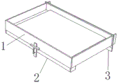
FIG. 1 is a schematic diagram of the overall structure of the present utility model;
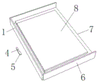
FIG. 2 is a schematic view of the structure of the base plate according to the present utility model;
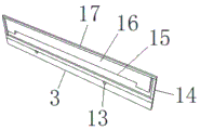
FIG. 3 is a schematic view of a moving plate according to the present utility model;
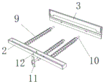
fig. 4 is a schematic structural view of a long rod in the present utility model.
Wherein: 1. a riser; 2. a long frame; 3. a moving plate; 4. a limit groove; 5. a fixed block; 6. a baffle; 7. a bottom plate; 8. a work table; 9. a spring; 10. a long rod; 11. a stop lever; 12. a circular groove; 13. a slot; 14. a connecting strip; 15. rectangular grooves; 16. a scraper; 17. a cross bar.
Detailed Description
In order that the manner in which the above recited features, objects and advantages of the present utility model are obtained will become readily apparent, a more particular description of the utility model will be rendered by reference to specific embodiments thereof which are illustrated in the appended drawings. Based on the examples in the embodiments, those skilled in the art can obtain other examples without making any inventive effort, which fall within the scope of the utility model. The experimental methods in the following examples are conventional methods unless otherwise specified, and materials, reagents, etc. used in the following examples are commercially available unless otherwise specified.
As shown in fig. 1-4, a punching machine for producing a keyboard bottom plate comprises a bottom plate 7 and a vertical plate 1, wherein the upper surface of the bottom plate 7 is fixedly connected with a workbench 8, the left end and the right end of the bottom plate 7 are fixedly connected with baffle plates 6, the two baffle plates 6 are respectively and fixedly connected with two ends of the vertical plate 1, a gap serving as a leakage groove exists between the vertical plate 1 and the bottom plate 7, the bottom surface of the bottom plate 7 is provided with a moving mechanism which comprises a moving plate 3 and a long frame 2, the long frame 2 is fixedly arranged at the gap between the vertical plate 1 and the bottom plate 7, the surface of the vertical plate 1, which is far away from the bottom plate 7, is fixedly connected with a fixed block 5, the surface of the fixed block 5, which faces the bottom plate 7, is provided with a limiting groove 4, the middle part of the long frame 2 penetrates through a circular groove 12, three long rods 10 are arranged between the long frame 2 and the moving plate 3, the rod surface of each long rod 10 is movably sleeved with a spring 9, two ends of the moving plate 3 are fixedly connected with a connecting strip 14, the upper ends of the two connecting strips 14 are fixedly connected with a transverse strip 17, the bottom surface of the transverse strip 17 is fixedly connected with a scraping plate 16, the bottom surface 16 is fixedly connected with a scraping plate 16, the middle part of the scraping plate 16 is provided with two middle parts of the scraping plate 16, and two middle parts of the scraping plate 3 are provided with two rectangular slots 13;
the long rod 10 at the left end and the right end is movably sleeved with the two slots 13 respectively, the front end of the long rod 10 in the middle is movably sleeved with the round slot 12, an operator pulls the stop rod 11 to move through the pull ring, the stop rod 11 moves to drive the long rod 10 in the middle to move, so that the movable plate 3 moves, the two ends of the three springs 9 are fixedly connected with the movable plate 3 and the long frame 2 respectively, the front end of the long rod 10 in the middle is fixedly connected with the stop rod 11, the middle part of the stop rod 11 is fixedly connected with the stop rod 11, the end part of the stop rod 11 is fixedly connected with the movable plate 4 in the middle and can be clamped in the stop slot 4, and the stop rod 11 is fixedly connected with the movable plate 4.
When the movable plate is used, an operator pulls the stop lever 11 to move through the pull ring, the stop lever 11 moves to drive the long rod 10 in the middle to move, so that the movable plate 3 moves, the scraper blade 16 is driven by the connecting bar 14 and the cross bar 17 to clean the bottom plate 7 and the metal slag scraps on the workbench 8 in the moving process of the movable plate 3 and push the metal slag scraps into the collecting tank below the long frame 2, no dead angle is cleaned, the movable plate can be automatically reset under the elasticity of the spring 9, the physical strength is effectively saved, the whole movable mechanism is positioned below the bottom plate 7 and between the two baffle plates 6, the occupied space is small, and the operator only needs to rotate the long rod 10 in the middle to clamp the stop lever 11 in the limiting tank 4, so that the long rod 10 is kept in a stable position, and the movable plate is simple and quick to operate.
The embodiments of the present utility model have been described in detail with reference to the drawings, but the present utility model is not limited thereto, and various changes can be made within the knowledge of those skilled in the art without departing from the spirit of the present utility model.
Claims (7)
1. The utility model provides a punching machine is used in keyboard bottom plate production, includes bottom plate (7) and riser (1), its characterized in that, the upper surface fixedly connected with workstation (8) of bottom plate (7), the left and right sides end of bottom plate (7) all fixedly connected with baffle (6), two baffle (6) respectively with riser (1) both ends fixed connection, there is the clearance as the hourglass between riser (1) and bottom plate (7);
the bottom surface of the bottom plate (7) is provided with a moving mechanism, and the moving mechanism comprises a moving plate (3) and a long frame (2);
the long frame (2) is fixedly arranged at a gap between the vertical plate (1) and the bottom plate (7).
2. The punching machine for producing the keyboard bottom plate according to claim 1, characterized in that a fixing block (5) is fixedly connected to the surface of the vertical plate (1) facing away from the bottom plate (7), and a limit groove (4) is formed in the surface of the fixing block (5) facing the bottom plate (7).
3. The punching machine for producing keyboard bottom plates according to claim 2, characterized in that a round groove (12) is penetrated in the middle part of the long frame (2), three long rods (10) are arranged between the long frame (2) and the moving plate (3), and the rod surface of each long rod (10) is movably sleeved with a spring (9).
4. A punching machine for producing a keyboard bottom plate according to claim 3, characterized in that both ends of the moving plate (3) are fixedly connected with connecting strips (14), and the upper ends of the two connecting strips (14) are fixedly connected with a cross strip (17).
5. The punching machine for producing keyboard bottom plates according to claim 4, characterized in that the bottom surface of the cross bar (17) is fixedly connected with a scraper blade (16), a rectangular groove (15) is formed in the middle part of the bottom surface of the scraper blade (16), and two slots (13) are formed in the middle part of the movable plate (3).
6. The punching machine for producing keyboard bottom plates according to claim 5, characterized in that the long rods (10) at the left end and the right end are movably sleeved with two slots (13) respectively, the front ends of the long rods (10) in the middle are movably sleeved with round slots (12), and the two ends of the three springs (9) are fixedly connected with the movable plate (3) and the long frame (2) respectively.
7. The punching machine for producing keyboard bottom plates according to claim 6, characterized in that the front end of the long rod (10) in the middle is fixedly connected with a stop lever (11), the rear end of the long rod (10) in the middle is rotationally connected with the movable plate (3), the middle part of the stop lever (11) is fixedly connected with a pull ring, and the end part of the stop lever (11) is movably clamped in the limiting groove (4).
Priority Applications (1)
| Application Number | Priority Date | Filing Date | Title |
|---|---|---|---|
| CN202320176715.7U CN219253794U (en) | 2023-02-10 | 2023-02-10 | Punching machine is used in keyboard bottom plate production |
Applications Claiming Priority (1)
| Application Number | Priority Date | Filing Date | Title |
|---|---|---|---|
| CN202320176715.7U CN219253794U (en) | 2023-02-10 | 2023-02-10 | Punching machine is used in keyboard bottom plate production |
Publications (1)
| Publication Number | Publication Date |
|---|---|
| CN219253794U true CN219253794U (en) | 2023-06-27 |
Family
ID=86858286
Family Applications (1)
| Application Number | Title | Priority Date | Filing Date |
|---|---|---|---|
| CN202320176715.7U Active CN219253794U (en) | 2023-02-10 | 2023-02-10 | Punching machine is used in keyboard bottom plate production |
Country Status (1)
| Country | Link |
|---|---|
| CN (1) | CN219253794U (en) |
-
2023
- 2023-02-10 CN CN202320176715.7U patent/CN219253794U/en active Active
Similar Documents
| Publication | Publication Date | Title |
|---|---|---|
| CN213887814U (en) | High-precision positioning punching die for workpiece of clamping piece of reactor | |
| CN118455892A (en) | Battery box friction stir welding presss from both sides tight frock | |
| CN211360288U (en) | A hemming device for processing a heat sink | |
| CN210999119U (en) | Grooving machine for basin stand processing | |
| CN214639269U (en) | A automatic leveling device for new energy automobile's stator and rotor blanking mould | |
| CN214321456U (en) | Chamfer blanking die | |
| CN216027371U (en) | Gantry punch press for Kovar ring | |
| CN218050592U (en) | Quick positioner is tailor to plate shearing machine | |
| CN216226462U (en) | A special mold for water heater waterway base components | |
| CN210586763U (en) | Continuous stamping die | |
| CN220679096U (en) | Waste material auxiliary collection structure of punching machine | |
| CN220805253U (en) | Punching machine convenient to surface cleaning | |
| CN214639752U (en) | Workpiece clamping mechanism convenient to replace and used for stamping machine | |
| CN217665804U (en) | Sheet metal stamping composite die | |
| CN221475260U (en) | Lithium ion battery diaphragm cuts structure | |
| CN221456902U (en) | Automatic precision press of slagging-off | |
| CN223733642U (en) | Automatic waste removal mold after asynchronous punching | |
| CN219043904U (en) | Asynchronous punching device convenient to collect | |
| CN212917801U (en) | Plate shearing machine for processing stainless steel plate | |
| CN222133628U (en) | Sheet metal mold processing device | |
| CN221909346U (en) | Porous piercing press of aluminium alloy | |
| CN222858107U (en) | Board punching device based on photovoltaic inverter production | |
| CN218801623U (en) | Pneumatic type bench vice clamping device | |
| CN212144676U (en) | Plate shearing machine suitable for processing of food iron cans | |
| CN223011659U (en) | Stamping die is used in hardware fitting production |
Legal Events
| Date | Code | Title | Description |
|---|---|---|---|
| GR01 | Patent grant | ||
| GR01 | Patent grant |