CN219252519U - Material making device - Google Patents
Material making device Download PDFInfo
- Publication number
- CN219252519U CN219252519U CN202223509120.3U CN202223509120U CN219252519U CN 219252519 U CN219252519 U CN 219252519U CN 202223509120 U CN202223509120 U CN 202223509120U CN 219252519 U CN219252519 U CN 219252519U
- Authority
- CN
- China
- Prior art keywords
- fixedly connected
- casing
- shell
- electric telescopic
- servo motor
- Prior art date
- Legal status (The legal status is an assumption and is not a legal conclusion. Google has not performed a legal analysis and makes no representation as to the accuracy of the status listed.)
- Active
Links
- 239000000463 material Substances 0.000 title claims abstract description 27
- 238000002360 preparation method Methods 0.000 claims description 9
- 238000003756 stirring Methods 0.000 claims description 8
- 238000000227 grinding Methods 0.000 claims description 6
- 230000005855 radiation Effects 0.000 claims description 6
- 238000001035 drying Methods 0.000 abstract description 8
- 239000002994 raw material Substances 0.000 description 8
- 238000010438 heat treatment Methods 0.000 description 6
- 238000000034 method Methods 0.000 description 6
- 238000011068 loading method Methods 0.000 description 5
- 241001465754 Metazoa Species 0.000 description 3
- 238000002156 mixing Methods 0.000 description 3
- 239000004519 grease Substances 0.000 description 2
- 238000004519 manufacturing process Methods 0.000 description 2
- 239000000843 powder Substances 0.000 description 2
- 235000019733 Fish meal Nutrition 0.000 description 1
- 244000068988 Glycine max Species 0.000 description 1
- 235000010469 Glycine max Nutrition 0.000 description 1
- 235000019735 Meat-and-bone meal Nutrition 0.000 description 1
- 240000006394 Sorghum bicolor Species 0.000 description 1
- 235000011684 Sorghum saccharatum Nutrition 0.000 description 1
- 235000019764 Soybean Meal Nutrition 0.000 description 1
- 239000005862 Whey Substances 0.000 description 1
- 102000007544 Whey Proteins Human genes 0.000 description 1
- 108010046377 Whey Proteins Proteins 0.000 description 1
- 240000008042 Zea mays Species 0.000 description 1
- 235000005824 Zea mays ssp. parviglumis Nutrition 0.000 description 1
- 235000002017 Zea mays subsp mays Nutrition 0.000 description 1
- 239000000654 additive Substances 0.000 description 1
- 230000004075 alteration Effects 0.000 description 1
- 235000001014 amino acid Nutrition 0.000 description 1
- 150000001413 amino acids Chemical class 0.000 description 1
- 230000009286 beneficial effect Effects 0.000 description 1
- 235000013339 cereals Nutrition 0.000 description 1
- 235000005822 corn Nutrition 0.000 description 1
- 238000010586 diagram Methods 0.000 description 1
- 238000006073 displacement reaction Methods 0.000 description 1
- 239000004467 fishmeal Substances 0.000 description 1
- 235000012054 meals Nutrition 0.000 description 1
- 239000000203 mixture Substances 0.000 description 1
- 238000012986 modification Methods 0.000 description 1
- 230000004048 modification Effects 0.000 description 1
- 235000015097 nutrients Nutrition 0.000 description 1
- 239000004455 soybean meal Substances 0.000 description 1
- 238000006467 substitution reaction Methods 0.000 description 1
Images


Classifications
-
- Y—GENERAL TAGGING OF NEW TECHNOLOGICAL DEVELOPMENTS; GENERAL TAGGING OF CROSS-SECTIONAL TECHNOLOGIES SPANNING OVER SEVERAL SECTIONS OF THE IPC; TECHNICAL SUBJECTS COVERED BY FORMER USPC CROSS-REFERENCE ART COLLECTIONS [XRACs] AND DIGESTS
- Y02—TECHNOLOGIES OR APPLICATIONS FOR MITIGATION OR ADAPTATION AGAINST CLIMATE CHANGE
- Y02P—CLIMATE CHANGE MITIGATION TECHNOLOGIES IN THE PRODUCTION OR PROCESSING OF GOODS
- Y02P70/00—Climate change mitigation technologies in the production process for final industrial or consumer products
- Y02P70/10—Greenhouse gas [GHG] capture, material saving, heat recovery or other energy efficient measures, e.g. motor control, characterised by manufacturing processes, e.g. for rolling metal or metal working
Landscapes
- Apparatuses For Bulk Treatment Of Fruits And Vegetables And Apparatuses For Preparing Feeds (AREA)
Abstract
The utility model relates to a material making device, which comprises a shell, wherein a drying assembly is arranged in the shell, the drying assembly comprises a first servo motor, a screw rod is fixedly connected with the first servo motor, a retainer is connected with screw threads, two guide rods are connected with the bottom of the retainer in a sliding manner, the two guide rods are fixedly connected to the inner bottom surface of the shell, a second servo motor is fixedly connected to the upper part of the retainer, a fan is fixedly connected to the output end of the second servo motor, a grid plate is fixedly connected to the inner bottom surface of the shell, and the grid plate is fixedly connected to the position, close to the fan, of the inner bottom surface of the shell.
Description
Technical Field
The utility model relates to the technical field of aquatic feed production equipment, in particular to a material preparation device.
Background
The term "feed" refers to a general term for animals raised by all humans, and the term "feed" in a relatively narrow sense refers mainly to a general term for animals raised in agriculture or in animal husbandry. The feed comprises more than ten varieties of feed raw materials such as soybean, soybean meal, corn, fish meal, amino acid, miscellaneous meal, additives, whey powder, grease, meat and bone meal, grains, sorghum and the like. In the aquatic feed production process, various nutrients processed into powder are required to be mutually stirred and mixed, and the aquatic feed is required to be prepared, so that different types of aquatic feed preparation and assembly appear in the market.
Chinese patent discloses an aquatic products fodder preparation device (CN 206472830U) the device cooperates through motor, output shaft, connecting axle, gear, crushing roller, stock guide, blending box, puddler, discharge gate and striker plate for this aquatic products fodder preparation device can smash and mix the raw materials, but when carrying out aquatic products fodder configuration under ordinary circumstances, all can contain some moisture and grease in the raw materials, and this aquatic products fodder preparation device machine fails to carry out timely stoving to the fodder after the pelleting is arranged, leads to the fodder to adhere together easily, influences the processing of follow-up fodder.
Disclosure of Invention
The utility model aims to provide a material preparation device for solving the problems in the background art.
In order to achieve the above purpose, the present utility model provides the following technical solutions: the utility model provides a material preparing device, includes the casing, the inside stoving subassembly that is provided with of casing, stoving subassembly is including first servo motor, first servo motor's output fixedly connected with lead screw, lead screw threaded connection has the holder, and two guide arms of holder bottom sliding connection, two guide arm fixed connection is in the inside bottom surface of casing, holder top fixedly connected with second servo motor, and second servo motor's output fixedly connected with fan is close to the position fixedly connected with grid of fan in the inside bottom surface of casing, grid one side fixedly connected with heater, and a plurality of heat radiation pipes of evenly fixedly connected with still are provided with on the inside bottom surface of casing, and the inside material subassembly that still is provided with of casing.
Further, get material subassembly including first electric telescopic handle and second electric telescopic handle, the stiff end fixed connection of first electric telescopic handle is on the inside bottom surface of casing, the removal end fixedly connected with layer board of first electric telescopic handle, the bottom surface of the top swing joint of layer board box that charges, second electric telescopic handle stiff end fixed connection is on the inside lateral wall of casing, the removal end fixedly connected with push pedal of second electric telescopic handle, the side swing joint box that charges of push pedal is the side, through the cooperation of first electric telescopic handle and layer board, can make the box that charges by the lifting.
Further, the discharge gate has been seted up to one side of casing, and the inside joint of casing has the baffle, has seted up the discharge gate through one side at the casing for the charging box can be released the discharge gate.
Further, the top fixedly connected with feed channel of casing, feed channel top fixedly connected with pouring gate, through pouring gate and feed channel cooperation, can make the raw materials pour into in the casing more conveniently.
Further, the top fixedly connected with mount of casing, fixedly connected with driving motor on the mount, driving motor output fixedly connected with pivot, pivot one end fixedly connected with driving gear, driving gear both sides all mesh and have driven gear, two driven gear equal fixedly connected with minor axis, two minor axis and the equal fixedly connected with grinding miller of pivot outer wall, the other end fixedly connected with cylindrical gear of pivot, the cylindrical gear meshing has the toothed disc, through the cooperation of pivot and grinding miller, can make the raw materials carry out a crushing treatment.
Further, fixedly connected with puddler in the middle of the gear plate, the puddler runs through the upper surface wall of casing, through the cooperation of gear plate and puddler, can make the puddler rotate, carries out intensive mixing to the fodder of casing inside.
Compared with the prior art, the technical scheme of the application has the following beneficial effects:
1. the utility model is provided with a drying component, the output end of the first servo motor drives the screw rod to rotate so as to drive the retainer to move forwards and backwards, the second servo motor on the retainer is driven to move forwards and backwards, the second servo motor rotates so as to drive the fan to rotate, and the heating wire on the grid plate is blown to blow hot air into the cavity for heating, and meanwhile, the heat radiation pipe on the bottom surface of the inner wall of the shell assists in heating so as to quickly dry the wet feed in the feeding box, so that the feed is not easy to adhere together, and the follow-up treatment of the feed is facilitated.
2. The utility model is provided with a material taking assembly, the supporting plate is jacked up through the extension of the moving end of the first electric telescopic rod, the charging box is placed above the supporting plate, the charging box is jacked up and pushed to the discharge hole, and the second electric telescopic rod is started to push the push plate to push the charging box out of the discharge hole.
Drawings
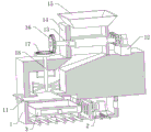
FIG. 1 is a schematic view of the overall structure of a material making apparatus according to the present utility model;
FIG. 2 is a schematic diagram of a drying assembly in a material making apparatus according to the present utility model;
FIG. 3 is a schematic view of a material taking assembly in a material making apparatus according to the present utility model;
fig. 4 is a schematic overall sectional view of a material making apparatus according to the present utility model.
In the figure: 1. a housing; 11. a baffle; 12. a fixing frame; 13. a rotating shaft; 14. a feed channel; 15. a material pouring opening; 16. a cylindrical gear; 17. a gear plate; 18. a stirring rod; 2. a drying assembly; 21. a first servo motor; 22. a screw rod; 23. a retainer; 24. a guide rod; 25. a second servo motor; 26. a fan; 27. a grid plate; 28. a heating wire; 29. a heat radiation pipe; 3. a material taking assembly; 31. a first electric telescopic rod; 32. a supporting plate; 33. a second electric telescopic rod; 34. a push plate; 301. and a charging box.
Detailed Description
The following description of the embodiments of the present utility model will be made clearly and completely with reference to the accompanying drawings, in which it is apparent that the embodiments described are only some embodiments of the present utility model, but not all embodiments. All other embodiments, which can be made by those skilled in the art based on the embodiments of the utility model without making any inventive effort, are intended to be within the scope of the utility model.
Referring to fig. 1-4, a material making device in this embodiment includes a housing 1, a drying assembly 2 is disposed inside the housing 1, the drying assembly 2 includes a first servo motor 21, an output end of the first servo motor 21 is fixedly connected with a screw 22, the screw 22 is in threaded connection with a retainer 23, a bottom of the retainer 23 is slidably connected with two guide rods 24, the two guide rods 24 are fixedly connected with a second servo motor 25 above the retainer 23, an output end of the second servo motor 25 is fixedly connected with a fan 26, a grid plate 27 is fixedly connected with a position, close to the fan 26, of the inner bottom surface of the housing 1, a heating wire 28 is fixedly connected with one side of the grid plate 27, a plurality of heat radiation pipes 29 are uniformly and fixedly connected to the inner bottom surface of the housing 1, and a material taking assembly 3 is further disposed inside the housing 1.
The material taking assembly 3 comprises a first electric telescopic rod 31 and a second electric telescopic rod 33, wherein the fixed end of the first electric telescopic rod 31 is fixedly connected to the inner bottom surface of the shell 1, the moving end of the first electric telescopic rod 31 is fixedly connected with a supporting plate 32, the top of the supporting plate 32 is movably connected with the bottom surface of the charging box 301, the fixed end of the second electric telescopic rod 33 is fixedly connected to the inner side wall of the shell 1, the moving end of the second electric telescopic rod 33 is fixedly connected with a push plate 34, the side surface of the push plate 34 is movably connected with the side surface of the charging box 301, and the charging box 301 can be lifted through the cooperation of the first electric telescopic rod 31 and the supporting plate 32.
A discharge port is formed in one side of the casing 1, the baffle 11 is clamped in the casing 1, and the discharge port is formed in one side of the casing 1, so that the charging box 301 can be pushed out of the discharge port.
The top fixedly connected with feed channel 14 of casing 1, feed channel 14 top fixedly connected with pouring spout 15, through pouring spout 15 and feed channel 14 cooperation, can make the raw materials pour into in the casing 1 more conveniently.
The top fixedly connected with mount 12 of casing 1, fixedly connected with driving motor on the mount 12, driving motor output fixedly connected with pivot 13, pivot 13 one end fixedly connected with driving gear, driving gear both sides all mesh and are had driven gear, two driven gears all fixedly connected with minor axis, two minor axes and pivot 13 outer wall all fixedly connected with grinding wheel, the other end fixedly connected with cylindrical gear 16 of pivot 13, cylindrical gear 16 meshing has gear disc 17, cooperation through pivot 13 and grinding wheel can make the raw materials carry out a crushing treatment
The stirring rod 18 is fixedly connected with in the middle of the gear disc 17, and the stirring rod 18 penetrates through the upper surface wall of the shell 1, and the stirring rod 18 can be rotated through the cooperation of the gear disc 17 and the stirring rod 18 to sufficiently stir feed in the shell 1.
The types of the first servo motor 21 and the second servo motor 25 are 42JSF330AS-1000, and the driving motor is GW INDUSTRY.
The working principle of the embodiment is as follows: raw materials get into from pouring hole 15, grind the back through the grinding wheel, fall to the inside puddler 18 department of casing 1, by puddler 18 intensive mixing back, fall into in the loading box 301, then drive lead screw 22 through the output of first servo motor 21 and rotate and thereby drive holder 23 and carry out the back-and-forth displacement, drive second servo motor 25 and the fan 26 on the holder 23 and carry out the back-and-forth movement, second servo motor 25 rotation drives fan 26 and rotates, blow in the heater 28 on the grid plate 27, thereby blow the steam into the cavity and heat, still heat radiation pipe 29 auxiliary heating of casing 1 inner wall bottom surface can carry out a flash drying with the moist fodder in the loading box 301 simultaneously, flexible jack-up with layer board 32 through the mobile end of first electric telescopic link 31, place loading box 301 above layer board 32, loading box 301 is just jacked up and is pushed to the discharge gate, start second electric telescopic link 33 promotes push pedal 34 and promotes loading box 301 and releases the discharge gate.
It is noted that relational terms such as first and second, and the like are used solely to distinguish one entity or action from another entity or action without necessarily requiring or implying any actual such relationship or order between such entities or actions. Moreover, the terms "comprises," "comprising," or any other variation thereof, are intended to cover a non-exclusive inclusion, such that a process, method, article, or apparatus that comprises a list of elements does not include only those elements but may include other elements not expressly listed or inherent to such process, method, article, or apparatus. Without further limitation, an element defined by the phrase "comprising one … …" does not exclude the presence of other like elements in a process, method, article, or apparatus that comprises the element.
Although embodiments of the present utility model have been shown and described, it will be understood by those skilled in the art that various changes, modifications, substitutions and alterations can be made therein without departing from the principles and spirit of the utility model, the scope of which is defined in the appended claims and their equivalents.
Claims (6)
1. The utility model provides a material preparing device, includes casing (1), its characterized in that, casing (1) inside is provided with stoving subassembly (2), and stoving subassembly (2) are including first servo motor (21), and the output fixedly connected with lead screw (22) of first servo motor (21), lead screw (22) threaded connection have holder (23), and holder (23) bottom sliding connection has two guide arms (24), two guide arm (24) fixed connection is in the inside bottom surface of casing (1), and holder (23) top fixedly connected with second servo motor (25), and the output fixedly connected with fan (26) of second servo motor (25) is close to position fixedly connected with grid board (27) of fan (26) in the inside bottom surface of casing (1), and grid board (27) one side fixedly connected with heater (28), still evenly fixedly connected with a plurality of heat radiation pipes (29) on the inside bottom surface of casing (1), still are provided with material taking module (3) inside casing (1).
2. The material preparing device according to claim 1, wherein the material extracting assembly (3) comprises a first electric telescopic rod (31) and a second electric telescopic rod (33), the fixed end of the first electric telescopic rod (31) is fixedly connected to the inner bottom surface of the shell (1), the moving end of the first electric telescopic rod (31) is fixedly connected with a supporting plate (32), the top of the supporting plate (32) is movably connected with the bottom surface of the charging box (301), the fixed end of the second electric telescopic rod (33) is fixedly connected to the inner side wall of the shell (1), the moving end of the second electric telescopic rod (33) is fixedly connected with a pushing plate (34), and the side surface of the pushing plate (34) is movably connected with the side surface of the charging box (301).
3. The material preparation device according to claim 1, wherein a discharge hole is formed in one side of the shell (1), and a baffle (11) is clamped in the shell (1).
4. A material preparation device according to claim 1, characterized in that the top of the housing (1) is fixedly connected with a feed channel (14), and the top of the feed channel (14) is fixedly connected with a material pouring opening (15).
5. The material preparation device according to claim 1, characterized in that the top of the shell (1) is fixedly connected with a fixing frame (12), a driving motor is fixedly connected to the fixing frame (12), a rotating shaft (13) is fixedly connected to the output end of the driving motor, a driving gear is fixedly connected to one end of the rotating shaft (13), driven gears are meshed to two sides of the driving gear, a short shaft is fixedly connected to two driven gears, grinding wheels are fixedly connected to the outer walls of the two short shafts and the rotating shaft (13), a cylindrical gear (16) is fixedly connected to the other end of the rotating shaft (13), and a gear disc (17) is meshed to the cylindrical gear (16).
6. A material-making device according to claim 5, characterized in that the middle of the gear disc (17) is fixedly connected with a stirring rod (18), and the stirring rod (18) penetrates through the upper surface wall of the shell (1).
Priority Applications (1)
| Application Number | Priority Date | Filing Date | Title |
|---|---|---|---|
| CN202223509120.3U CN219252519U (en) | 2022-12-28 | 2022-12-28 | Material making device |
Applications Claiming Priority (1)
| Application Number | Priority Date | Filing Date | Title |
|---|---|---|---|
| CN202223509120.3U CN219252519U (en) | 2022-12-28 | 2022-12-28 | Material making device |
Publications (1)
| Publication Number | Publication Date |
|---|---|
| CN219252519U true CN219252519U (en) | 2023-06-27 |
Family
ID=86870259
Family Applications (1)
| Application Number | Title | Priority Date | Filing Date |
|---|---|---|---|
| CN202223509120.3U Active CN219252519U (en) | 2022-12-28 | 2022-12-28 | Material making device |
Country Status (1)
| Country | Link |
|---|---|
| CN (1) | CN219252519U (en) |
-
2022
- 2022-12-28 CN CN202223509120.3U patent/CN219252519U/en active Active
Similar Documents
| Publication | Publication Date | Title |
|---|---|---|
| CN219765252U (en) | Feed granulating device capable of improving feed utilization rate | |
| CN219037443U (en) | Manure production granulation drying integrated machine | |
| CN107824087A (en) | A kind of quota of feed matches agitating device | |
| CN107667886A (en) | The feed stuff agitating device of the automatic transport of one boar cultivation | |
| CN213854403U (en) | A pelletization device for feed processing | |
| CN219674597U (en) | Drying device is used in feed production processing | |
| CN210796280U (en) | An intelligent stirring device for microbial organic fertilizer production | |
| CN220879106U (en) | Feed mixing device for black pig breeding | |
| CN218480886U (en) | Microwave drying device for solid-state fermented feed | |
| CN210832963U (en) | Saving type fodder drying device | |
| CN108095161A (en) | Feed pellet making machine for livestock and poultry breeding | |
| CN208679070U (en) | A kind of pelletizer that organic fertilizer production noise pollution is small | |
| CN221948984U (en) | Forage tank and forage feeding equipment for animal farm | |
| CN220274557U (en) | A feeding device for distiller's grain feed for breeding | |
| CN222678175U (en) | A crushing device with drying structure | |
| CN219301247U (en) | Dryer for feed production | |
| CN220062414U (en) | Mixed material dryer with uniform stirring | |
| CN220476592U (en) | Pig house feeding equipment for live pig breeding | |
| CN221062403U (en) | Material stirring device for dog food processing | |
| CN220879192U (en) | An iron slag removal device for livestock feed processing machinery | |
| CN221166442U (en) | Device for recycling agricultural waste | |
| CN215743979U (en) | Lobster particle formula feed processing shaping reducing mechanism | |
| CN222187612U (en) | A biological organic fertilizer drying device | |
| CN221464189U (en) | Tablet corn feed drying device | |
| CN220716021U (en) | Sheep feed crushing device |
Legal Events
| Date | Code | Title | Description |
|---|---|---|---|
| GR01 | Patent grant | ||
| GR01 | Patent grant |