CN219235989U - Breathing machine mesochite injection mold - Google Patents
Breathing machine mesochite injection mold Download PDFInfo
- Publication number
- CN219235989U CN219235989U CN202223302090.9U CN202223302090U CN219235989U CN 219235989 U CN219235989 U CN 219235989U CN 202223302090 U CN202223302090 U CN 202223302090U CN 219235989 U CN219235989 U CN 219235989U
- Authority
- CN
- China
- Prior art keywords
- bed die
- die
- injection mold
- last mould
- breathing machine
- Prior art date
- Legal status (The legal status is an assumption and is not a legal conclusion. Google has not performed a legal analysis and makes no representation as to the accuracy of the status listed.)
- Active
Links
- 230000029058 respiratory gaseous exchange Effects 0.000 title claims abstract description 23
- 238000002347 injection Methods 0.000 title claims abstract description 17
- 239000007924 injection Substances 0.000 title claims abstract description 17
- 238000007493 shaping process Methods 0.000 claims abstract description 14
- 238000010030 laminating Methods 0.000 claims abstract description 4
- 239000007788 liquid Substances 0.000 claims description 10
- 238000001746 injection moulding Methods 0.000 abstract description 17
- 238000004519 manufacturing process Methods 0.000 abstract description 8
- 238000000465 moulding Methods 0.000 description 8
- 238000007789 sealing Methods 0.000 description 5
- 239000000463 material Substances 0.000 description 4
- 238000004544 sputter deposition Methods 0.000 description 4
- 239000012778 molding material Substances 0.000 description 3
- 238000000034 method Methods 0.000 description 2
- 230000009286 beneficial effect Effects 0.000 description 1
- 238000004891 communication Methods 0.000 description 1
- 230000007423 decrease Effects 0.000 description 1
- 238000010586 diagram Methods 0.000 description 1
- 238000005516 engineering process Methods 0.000 description 1
- 238000012423 maintenance Methods 0.000 description 1
- 239000004033 plastic Substances 0.000 description 1
- 229920003023 plastic Polymers 0.000 description 1
- 230000000630 rising effect Effects 0.000 description 1
- 239000000243 solution Substances 0.000 description 1
Images


Landscapes
- Respiratory Apparatuses And Protective Means (AREA)
Abstract
The utility model relates to the technical field of production of shells in respirators, in particular to an injection mold for shells in respirators. The technical proposal comprises: base, bed die and last mould, the top face of base is provided with the bed die, install the bolt through the screw thread in the base, and the bolt passes through the screw thread to be installed in the bed die, install the dead lever through the connecting block in the bed die, sealed pad is installed in the laminating of the bottom face of going up the mould, and has seted up the cavity in the last mould, install the dead lever on the connecting block, and be provided with the cylinder in the dead lever, install the connecting rod in the bed die, and the connecting rod slip cup joints in last mould, bed die and last mould internal shaping have the breathing machine mesochite body. The shell in the breathing machine is subjected to injection molding, so that demolding is more convenient, and damage caused by mistaken touch to the molded shell is prevented during unfolding.
Description
Technical Field
The utility model relates to the technical field of production of shells in respirators, in particular to an injection mold for shells in respirators.
Background
Injection molding, also known as injection molding, is a method of injection and molding. The injection molding method has the advantages of high production speed, high efficiency, automation in operation, multiple patterns, various shapes, large size, accurate product size, easy updating of the product, and capability of forming parts with complex shapes, and is suitable for the field of mass production, products with complex shapes and other molding processing.
Most of shells in the existing breathing machine are produced in the later period of convenience in injection molding during production, but demolding production is inconvenient in the production process, and the produced shells are influenced by easy stress deflection of a mold during unfolding after injection molding, so that later production and processing are influenced.
Disclosure of Invention
The utility model aims to provide an injection mold for a middle shell of a breathing machine, which aims to solve the problems in the background technology.
In order to achieve the above purpose, the present utility model provides the following technical solutions: the utility model provides a shell injection mold in breathing machine, includes base, bed die and last mould, the top face of base is provided with the bed die, install the dead lever through the connecting block in the bed die, sealed pad is installed in the bottom face laminating of going up the mould, and has seted up the cavity in the last mould, install the connecting rod in the bed die, and the connecting rod slides and cup joints in last mould, bed die and last mould internal shaping have the breathing machine mesochite body.
Preferably, the base is internally provided with a bolt through threads, and the bolt is arranged in the lower die through threads. Install in the bed die through the screw thread through the bolt, conveniently install the bed die on the base, and make things convenient for the later stage to install and dismantle the bed die and maintain and overhaul.
Preferably, the connecting block is welded with a spring, and the size of the spring is matched with the inner diameter of the lower die. The connecting block is welded with a spring, so that when the upper die moves downwards to contact the lower die, the spring firstly contacts the upper die to slow down the impact force, and the sealing gasket at the bottom end surface of the upper die is used for closing during molding and injection molding.
Preferably, a fixing rod is arranged on the connecting block, and an air cylinder is arranged in the fixing rod. Through being provided with the cylinder in the dead lever, make the mould inner shell body after carrying out the shaping, personnel can open the cylinder and promote the mould and go up the removal, make things convenient for the later stage to open and the drawing of patterns.
Preferably, a connecting pipe is embedded and fixed in the upper die, and the connecting pipe is communicated with the cavity. The connecting pipe is communicated with the cavity, so that injection molding materials enter the cavity through the connecting pipe and are combined with the lower die to be molded, and the molded material is molded into the middle shell body of the breathing machine.
Preferably, the top end surface of the upper die is embedded and fixed with a liquid inlet pipe, and the liquid inlet pipe is communicated with the cavity. Through feed liquor pipe and cavity body intercommunication, make personnel accessible feed liquor pipe embedding fix carry out the feed liquor in the connecting pipe, prevent that direct feed liquor from causing the quality after the sputtering influence shaping.
Preferably, a screw is installed in the lower die through threads, and the screw is embedded and fixed in the upper die. The lower die and the upper die are connected and then are firmer through embedding and fixing the screw rod in the upper die.
Compared with the prior art, the utility model has the following beneficial effects:
1. according to the utility model, by arranging the lower die, when a person performs injection molding on the middle shell of the breathing machine, the lower die is arranged in the lower die through the screw threads, so that the lower die is conveniently arranged on the base, the lower die is conveniently installed and disassembled in the later stage for maintenance and overhaul, the spring is welded on the connecting block, when the upper die moves downwards to contact with the lower die, the spring firstly contacts with the upper die to slow down the impact force, the sealing pad on the bottom end surface of the upper die is used for closing during molding injection, and the air cylinder is arranged in the fixing rod, so that after the inner shell of the die is molded, the person can open the air cylinder to push the upper die to move upwards, the later stage is convenient to open and demold, the practicability is higher, and the later stage is convenient for injection molding and demolding.
2. According to the utility model, by arranging the upper die, when a person performs injection molding on the shell in the breathing machine, the person is communicated with the cavity through the liquid inlet pipe, so that the person can insert and fix the liquid inlet pipe in the connecting pipe to prevent sputtering caused by direct liquid inlet from influencing the quality after molding, and is communicated with the cavity through the connecting pipe, so that the injection molding material enters the cavity through the connecting pipe and is combined with the lower die to be molded, and the molded material is molded into the shell body in the breathing machine, and when the upper die is pushed by the air cylinder to move upwards in the later stage, the upper die is sleeved on the connecting rod in a sliding manner to limit, the stability of lifting and descending of the upper die is maintained, and damage to the molded shell due to offset is prevented.
Drawings
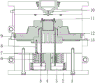
FIG. 1 is a schematic diagram of a front view of the present utility model;
FIG. 2 is a schematic side view of the present utility model;
fig. 3 is a schematic view of a shell body structure of the respirator of the present utility model.
In the figure: 1. a screw; 2. a base; 3. connecting block the method comprises the steps of carrying out a first treatment on the surface of the; 4. a lower die; 5. a connecting rod; 6. a spring; 7. a fixed rod; 8. a cylinder; 9. an upper die; 10. a liquid inlet pipe; 11. a connecting pipe; 12. a cavity; 13. a sealing gasket; 14. a bolt; 15. a shell body in a breathing machine.
Detailed Description
The following description of the embodiments of the present utility model will be made clearly and completely with reference to the accompanying drawings, in which it is apparent that the embodiments described are only some embodiments of the present utility model, but not all embodiments. All other embodiments, which can be made by those skilled in the art based on the embodiments of the utility model without making any inventive effort, are intended to be within the scope of the utility model.
In the description of the present utility model, it should be noted that the directions or positional relationships indicated by the terms "upper", "lower", "inner", "outer", "front", "rear", "both ends", "one end", "the other end", etc. are based on the directions or positional relationships shown in the drawings, are merely for convenience of describing the present utility model and simplifying the description, and do not indicate or imply that the devices or elements referred to must have a specific direction, be configured and operated in the specific direction, and thus should not be construed as limiting the present utility model. Furthermore, the terms "first," "second," and the like, are used for descriptive purposes only and are not to be construed as indicating or implying relative importance.
In the description of the present utility model, it should be noted that, unless explicitly specified and limited otherwise, the terms "mounted," "provided," "connected," and the like are to be construed broadly, and may be fixedly connected, detachably connected, or integrally connected, for example; can be mechanically or electrically connected; can be directly connected or indirectly connected through an intermediate medium, and can be communication between two elements. The specific meaning of the above terms in the present utility model will be understood in specific cases by those of ordinary skill in the art.
Example 1
As shown in fig. 1-3, the injection mold for the middle shell of the breathing machine provided by the utility model comprises a base 2, a lower mold 4 and an upper mold 9, wherein the lower mold 4 is arranged on the top end surface of the base 2, a fixed rod 7 is arranged in the lower mold 4 through a connecting block 3, a sealing gasket 13 is arranged on the bottom end surface of the upper mold 9 in a fitting manner, a cavity 12 is arranged in the upper mold 9, a connecting rod 5 is arranged in the lower mold 4, and the connecting rod 5 is sleeved in the upper mold 9 in a sliding manner.
The bolt 14 is installed through the screw thread in the base 2, and the bolt 14 passes through the screw thread to be installed in the bed die 4, passes through the screw thread to be installed in the bed die 4 through the bolt 14, conveniently installs the bed die 4 on the base 2, and conveniently installs and dismantles the bed die 4 at the later stage and maintain and overhaul.
The connecting block 3 is welded with the spring 6, the size of the spring 6 is matched with the inner diameter of the lower die 4, the spring 6 is welded on the connecting block 3, when the upper die 9 moves downwards to contact the lower die 4, the spring 6 firstly contacts the upper die 9 to slow down the impact force, and the sealing gasket 13 on the bottom end surface of the upper die 9 is used for closing during molding and injection molding.
Install dead lever 7 on the connecting block 3, and be provided with cylinder 8 in the dead lever 7, be provided with cylinder 8 in through dead lever 7, make the mould inner shell after carrying out the shaping, personnel can open cylinder 8 and promote mould 9 and shift up, make things convenient for the later stage to open and the drawing of patterns.
The lower die 4 and the upper die 9 are internally provided with a breathing machine middle shell body 15.
Based on example 1: personnel are when carrying out injection moulding to the breathing machine mesochite, install in bed die 4 through the screw thread through bolt 14, conveniently install bed die 4 on base 2, and make things convenient for the later stage to install and dismantle bed die 4 and maintain and overhaul, and when having spring 6 through the connecting block 3 upper die 9 to move down contact bed die 4, at first contact upper die 9 through spring 6 slows down the impact force, and close when making the shaping injection moulding through the sealed pad 13 of upper die 9 bottom end face, and be provided with cylinder 8 in through dead lever 7, make the interior casing of mould after carrying out the shaping, personnel can open cylinder 8 and promote upper die 9 and move up, make things convenient for the later stage to open and drawing of patterns.
Example two
As shown in fig. 1-3, the injection mold for a middle shell of a breathing machine according to the present utility model further includes: base 2, bed die 4 and last mould 9, the top face of base 2 is provided with bed die 4.
The connecting pipe 11 is fixedly embedded in the upper die 9, the connecting pipe 11 is communicated with the cavity 12, and is communicated with the cavity 12 through the connecting pipe 11, so that injection molding materials enter the cavity 12 through the connecting pipe 11 to be combined with the lower die 4 for molding, and the molded material is molded into the middle shell body 15 of the breathing machine.
The top end surface of the upper die 9 is embedded and fixed with a liquid inlet pipe 10, and the liquid inlet pipe 10 is communicated with a cavity 12. Through feed liquor pipe 10 and cavity 12 being linked together, make personnel accessible feed liquor pipe 10 imbeds and fix in connecting pipe 11 carries out the feed liquor, prevent that direct feed liquor from causing the sputtering to influence the quality after the shaping.
Screw 1 is installed through the screw thread in lower mould 4, and screw 1 embedding is fixed in last mould 9, through screw 1 embedding fixed in last mould 9, makes lower mould 4 and last mould 9 connect the back more firm.
The dead lever 7 is installed through connecting block 3 in the bed die 4, and sealed pad 13 is installed in the laminating of the bottom face of last mould 9, and has seted up cavity 12 in the last mould 9, installs connecting rod 5 in the bed die 4, and connecting rod 5 slip cup joints in last mould 9, and bed die 4 and last mould 9 internal shaping have breathing machine mesochite body 15.
Based on example 2: personnel are in the injection moulding to the shell in the breathing machine, be linked together through feed liquor pipe 10 and cavity 12, make personnel accessible feed liquor pipe 10 embedding fix and carry out the feed liquor in connecting pipe 11, prevent that direct feed liquor from causing the quality after the sputtering influence shaping, and be linked together through connecting pipe 11 and cavity 12, make the material of moulding plastics get into in the cavity 12 through connecting pipe 11 and the combination of bed die 4 and take shape, the shaping is shell body 15 in the breathing machine after the shaping, later stage when cylinder 8 promotes mould 9 and moves up, make mould 9 slip cup joint and carry out spacing on connecting rod 5, keep the stability of mould 9 rising and decline, prevent that the skew from causing the damage to the casing after the shaping.
It will be evident to those skilled in the art that the utility model is not limited to the details of the foregoing illustrative embodiments, and that the present utility model may be embodied in other specific forms without departing from the spirit or essential characteristics thereof. The present embodiments are, therefore, to be considered in all respects as illustrative and not restrictive, the scope of the utility model being indicated by the appended claims rather than by the foregoing description, and all changes which come within the meaning and range of equivalency of the claims are therefore intended to be embraced therein. Any reference sign in a claim should not be construed as limiting the claim concerned.
Claims (7)
1. The utility model provides a shell injection mold in breathing machine, includes base (2), bed die (4) and last mould (9), its characterized in that: the top surface of base (2) is provided with bed die (4), install dead lever (7) through connecting block (3) in bed die (4), sealed pad (13) are installed in the bottom surface laminating of last mould (9), and have seted up cavity (12) in last mould (9), install connecting rod (5) in bed die (4), and connecting rod (5) slip cup joint in last mould (9), bed die (4) and last mould (9) internal shaping have breathing machine mesochite body (15).
2. The ventilator center housing injection mold of claim 1, wherein: a bolt (14) is arranged in the base (2) through threads, and the bolt (14) is arranged in the lower die (4) through threads.
3. The ventilator center housing injection mold of claim 1, wherein: the connecting block (3) is welded with a spring (6), and the size of the spring (6) is matched with the inner diameter of the lower die (4).
4. The ventilator center housing injection mold of claim 1, wherein: a fixed rod (7) is arranged on the connecting block (3), and an air cylinder (8) is arranged in the fixed rod (7).
5. The ventilator center housing injection mold of claim 1, wherein: a connecting pipe (11) is embedded and fixed in the upper die (9), and the connecting pipe (11) is communicated with the cavity (12).
6. The ventilator center housing injection mold of claim 1, wherein: the top end surface of the upper die (9) is embedded and fixed with a liquid inlet pipe (10), and the liquid inlet pipe (10) is communicated with the cavity (12).
7. The ventilator center housing injection mold of claim 1, wherein: the lower die (4) is internally provided with a screw (1) through threads, and the screw (1) is embedded and fixed in the upper die (9).
Priority Applications (1)
| Application Number | Priority Date | Filing Date | Title |
|---|---|---|---|
| CN202223302090.9U CN219235989U (en) | 2022-12-07 | 2022-12-07 | Breathing machine mesochite injection mold |
Applications Claiming Priority (1)
| Application Number | Priority Date | Filing Date | Title |
|---|---|---|---|
| CN202223302090.9U CN219235989U (en) | 2022-12-07 | 2022-12-07 | Breathing machine mesochite injection mold |
Publications (1)
| Publication Number | Publication Date |
|---|---|
| CN219235989U true CN219235989U (en) | 2023-06-23 |
Family
ID=86844214
Family Applications (1)
| Application Number | Title | Priority Date | Filing Date |
|---|---|---|---|
| CN202223302090.9U Active CN219235989U (en) | 2022-12-07 | 2022-12-07 | Breathing machine mesochite injection mold |
Country Status (1)
| Country | Link |
|---|---|
| CN (1) | CN219235989U (en) |
-
2022
- 2022-12-07 CN CN202223302090.9U patent/CN219235989U/en active Active
Similar Documents
| Publication | Publication Date | Title |
|---|---|---|
| CN109702929A (en) | A kind of molding die of Filament-Winding Vessel sand core mould | |
| CN110202751A (en) | A kind of injection mould slanted structure | |
| CN217257654U (en) | Composite material special pipe forming die | |
| CN219855568U (en) | A mass production mold for relay shells | |
| CN209918847U (en) | Die casting die with structure of loosing core | |
| CN214562365U (en) | Bowl-shaped plug rapid prototyping device | |
| CN219727009U (en) | Lottery ticket machine front shell forming die | |
| CN210336980U (en) | Composite material special-shaped section closed angle eliminating tool | |
| CN210590383U (en) | An injection mold for automobile lampshade | |
| CN210349563U (en) | Magnetic core mould convenient to dismantle and wash | |
| CN208410437U (en) | Plate molding type carries molding equipment | |
| CN216139344U (en) | Injection mold is used in production of cell-phone shell | |
| CN212097305U (en) | Combined injection mold | |
| CN204685952U (en) | For the preparation of the main core cold-box of diesel engine mould | |
| CN221475952U (en) | A mold for high-strength battery box shell | |
| CN221873030U (en) | An injection mold | |
| CN211221801U (en) | Combined LED injection mold | |
| CN219114700U (en) | Blowing device of mold demolding mechanism | |
| CN221562003U (en) | Oil pan die | |
| CN217862574U (en) | Integral type electrosphygmomanometer shell injection mold | |
| CN224170336U (en) | Novel plastic suction mould | |
| CN221622876U (en) | Forming die of plastic framework | |
| CN214111262U (en) | Mold for manufacturing silica gel four-way joint | |
| CN220970568U (en) | Mould convenient to installation | |
| CN216267417U (en) | Shell injection mold |
Legal Events
| Date | Code | Title | Description |
|---|---|---|---|
| GR01 | Patent grant | ||
| GR01 | Patent grant |