CN219229660U - Simple oven - Google Patents
Simple oven Download PDFInfo
- Publication number
- CN219229660U CN219229660U CN202223293299.3U CN202223293299U CN219229660U CN 219229660 U CN219229660 U CN 219229660U CN 202223293299 U CN202223293299 U CN 202223293299U CN 219229660 U CN219229660 U CN 219229660U
- Authority
- CN
- China
- Prior art keywords
- main body
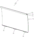
- oven
- hand dish
- reflecting piece
- inclined surface
- Prior art date
- Legal status (The legal status is an assumption and is not a legal conclusion. Google has not performed a legal analysis and makes no representation as to the accuracy of the status listed.)
- Active
Links
- 238000005192 partition Methods 0.000 claims abstract description 20
- 238000010411 cooking Methods 0.000 claims abstract description 18
- 238000009434 installation Methods 0.000 claims abstract description 15
- 238000010438 heat treatment Methods 0.000 claims abstract description 13
- 239000004519 grease Substances 0.000 claims description 8
- 235000007164 Oryza sativa Nutrition 0.000 claims description 4
- 235000009566 rice Nutrition 0.000 claims description 4
- 239000004576 sand Substances 0.000 claims description 4
- 240000007594 Oryza sativa Species 0.000 claims 1
- 238000010792 warming Methods 0.000 claims 1
- 235000013305 food Nutrition 0.000 description 6
- 238000010586 diagram Methods 0.000 description 5
- 235000021168 barbecue Nutrition 0.000 description 4
- 230000000694 effects Effects 0.000 description 4
- 241000209094 Oryza Species 0.000 description 3
- 239000007788 liquid Substances 0.000 description 2
- 206010053615 Thermal burn Diseases 0.000 description 1
- 230000009286 beneficial effect Effects 0.000 description 1
- 239000000463 material Substances 0.000 description 1
- 239000008188 pellet Substances 0.000 description 1
Images






Landscapes
- Baking, Grill, Roasting (AREA)
Abstract
The utility model relates to a simple oven, which comprises a first main body, wherein an installation gap is formed between the two first main bodies, the two first main bodies are fixedly connected together through a first cross rod arranged in the installation gap, the first cross rod is arranged at the upper end of the first main body and positioned at two sides of the first cross rod, a cooking utensil is detachably connected to the first cross rod, a heating component, a reflecting piece and an oil receiving component are also arranged below the first cross rod in sequence from top to bottom, first raised strips positioned in the installation gap are respectively arranged at two sides of the first main body, a partition plate is detachably connected to the first raised strips, and when the simple oven is used, the partition plate is arranged at one side or two sides of the first main body, so that the position of the partition plate can be adjusted at any time, and scalding and fire are avoided.
Description
[ field of technology ]
The utility model relates to the technical field of household appliances, in particular to a simple oven.
[ background Art ]
With the continuous progress of human life, people like camping and other outdoor activities in holiday leisure time, a great amount of food materials and tools are usually required to be carried in the outdoor activities, for example, U.S. patent publication No. US16677995 discloses a pellet grill, and the barbecue equipment can bake numerous things at one time, but has overlarge volume, is not suitable for being moved in a large range, and can possibly cause parts to be separated from and damaged during the movement, so that the barbecue equipment is not suitable for modern portable camping.
The prior art therefore does not meet our needs.
[ utility model ]
In order to solve the problems, the utility model provides a simple oven which is convenient to carry.
In order to achieve the above purpose, the present utility model provides the following technical solutions:
the utility model provides a simple and easy oven, includes first main part, two be formed with the installation clearance between the first main part, two first main part is in through setting up first horizontal pole fixed connection in the installation clearance is in the same place, first horizontal pole sets up the upper end of first main part and be located its both sides, can dismantle on the first horizontal pole and be connected with cooking utensil, heating element, reflector and oil receiving subassembly have still been set gradually from last to down to the below of first horizontal pole, the both sides of first main part are provided with respectively and are located first sand grip in the installation clearance, can dismantle on the first sand grip and be connected with the baffle, during the use the baffle sets up on one of them one side or the both sides of first main part.
As a preferred embodiment, further defined as: the partition plate comprises a second main body, a transverse connecting part and a longitudinal limiting part, wherein the transverse connecting part and the longitudinal limiting part are arranged on one side of the second main body, and a containing groove for the first raised line to be inserted is formed between the second main body and the longitudinal limiting part.
As a preferred embodiment, further defined as: the reflecting piece is in a V-shaped structure, so that the reflecting piece is formed with a first inclined plane and a second inclined plane, and an angle a formed between the first inclined plane and the second inclined plane is 170+/-10 degrees.
As a preferred embodiment, further defined as: the oil leakage holes aligned with the oil receiving component after assembly are formed in the first inclined plane and the second inclined plane, so that grease is converged on the reflecting piece and flows down to the oil receiving component.
As a preferred embodiment, further defined as: the two sides of the first main body are provided with second raised strips for placing the reflecting piece, the reflecting piece is provided with a limiting flanging, and the reflecting piece is detachably connected to the second raised strips.
As a preferred embodiment, further defined as: the oil receiving assembly comprises a fixing piece fixedly connected with the first main body and an oil receiving disc placed on the fixing piece.
As a preferred embodiment, further defined as: the partition board is also provided with a plurality of cutting bars positioned on the other side of the second main body, and the fixing piece is provided with a slot for inserting the cutting bars during assembly.
As a preferred embodiment, further defined as: the second cross rod between the reflecting piece and the oil receiving component is further arranged between the two first main bodies, a hand dish is arranged on the second cross rod, a second clamping groove for clamping the second cross rod is formed in the hand dish, and the hand dish is placed on the hand dish.
As a preferred embodiment, further defined as: the cooking utensil includes not with hand dish and hand dish simultaneous usage's oil leak type utensil and can with hand dish and hand dish simultaneous usage hold type utensil, oil leak type utensil includes roast net, gridiron, hold type utensil and include overware, boiler, side pot, saucepan, rice cooker, temperature wine pot, snow and draw the bowl.
As a preferred embodiment, further defined as: the portable computing device comprises a first main body, wherein a control panel electrically connected with the heating component is arranged in the first main body, a Bluetooth module is arranged on the control panel, the oven is connected with the portable computing device through the Bluetooth module, and the portable computing device is used for controlling the switch, the temperature and the baking time of the oven.
The beneficial effects of the utility model are as follows: the utility model discloses a simple oven, which comprises a first main body, wherein an installation gap is formed between the two first main bodies, the two first main bodies are fixedly connected together through a first cross rod arranged in the installation gap, the first cross rod is arranged at the upper end of the first main body and positioned at two sides of the first cross rod, a cooking utensil is detachably connected to the first cross rod, a heating component, a reflecting piece and an oil receiving component are sequentially arranged below the first cross rod from top to bottom, first raised strips positioned in the installation gap are respectively arranged at two sides of the first main body, and a partition plate is detachably connected to the first raised strips and is arranged at one side or two sides of the first main body when the simple oven is used. The oven is small and exquisite in overall shape, convenient to carry, and convenience of customers carries with oneself and carries out outdoor activities such as camping, is fit for modern lightweight camping, and cooking utensil, reflector, the oil receiving subassembly of oven and baffle all can dismantle with first main part simultaneously and be connected, and convenience of customers dismantles its clearance, also can dismantle it and fix and place when needs transport, avoids the part to break away from damage, barbecue equipment's damage when the transport to the baffle can be in according to user's use habit, electric wire place, the position of placing of oven and cooking needs to set up on one of them one side or the both sides of first main part, adjusts the position of baffle at any time, avoids scalding and fire.
[ description of the drawings ]
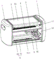
FIG. 1 is one of the structural schematic diagrams of the present utility model;
FIG. 2 is a second schematic diagram of the structure of the present utility model;
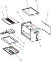
FIG. 3 is an exploded view of the present utility model;
FIG. 4 is a cross-sectional view of the present utility model;
FIG. 5 is an enlarged schematic view of A in FIG. 4;
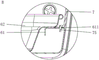
FIG. 6 is an enlarged schematic view of B in FIG. 4;
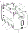
FIG. 7 is a third schematic diagram of the structure of the present utility model;
FIG. 8 is a schematic structural view of a reflector;
FIG. 9 is a schematic view of the structure of the separator;
FIG. 10 is one of the usage patterns of the present utility model;
FIG. 11 is a second view of the present utility model;
FIG. 12 is a third view of the use of the present utility model;
FIG. 13 is a fourth view of the use state of the present utility model;
FIG. 14 is a fifth state diagram of the present utility model;
FIG. 15 is a sixth state diagram of the use of the present utility model;
fig. 16 is a schematic structural view of a boiler.
[ detailed description ] of the utility model
The utility model is described in further detail below with reference to the attached drawings and detailed description:
as shown in fig. 1 to 16, a simple oven comprises a first main body 1, an installation gap 10 is formed between the two first main bodies 1, the two first main bodies 1 are fixedly connected together through a first transverse rod 2 arranged in the installation gap 10, the first transverse rod 2 is arranged at the upper end of the first main body 1 and positioned at two sides of the first main body, a cooking utensil 3 is detachably connected to the first transverse rod 2, a heating component 4, a reflecting piece 5 and an oil receiving component 6 are sequentially arranged below the first transverse rod 2 from top to bottom, first raised strips 11 positioned in the installation gap 10 are respectively arranged at two sides of the first main body 1, a partition 7 is detachably connected to the first raised strips 11, and the partition 7 is arranged at one side or two sides of the first main body 1 in use. The oven overall modeling is small and exquisite, and convenient transport, convenience of customers hand-carries outdoor activities such as camping, is fit for modern lightweight camping, and cooking utensil, reflector, the oil receiving subassembly of oven and baffle all can dismantle with first main part 1 simultaneously and be connected, and convenience of customers dismantles its clearance, also can dismantle it and fix and place when needs transport, avoids part break away from damage, barbecue equipment's damage when the transport to baffle 7 can be according to user's use habit, electric wire place, the place of oven and cooking needs to set up on one of them one side or the both sides of first main part 1, adjusts the position of baffle 7 at any time, avoids scalding and fire.
As shown in fig. 3 to 7 and 9, in the present embodiment, the partition 7 includes a second body 71, a lateral connection portion 72 provided at one side of the second body 71, and a longitudinal limit portion 73, and a receiving groove 74 into which the first protrusion 11 is inserted is formed between the second body 71 and the longitudinal limit portion 73. The transverse connection portion 72 and the longitudinal limiting portion 73 form a clamping hook, so that the partition 7 is conveniently and directly hung on the first raised strip 11, and meanwhile, a user can conveniently take down the partition in time to clean the partition or safely store the partition.
As shown in fig. 3 to 8, in the present embodiment, the reflecting member 5 has a V-shaped structure such that the reflecting member 5 is formed with a first inclined surface 51 and a second inclined surface 52, and an angle a formed between the first inclined surface 51 and the second inclined surface 52 is 170 ° ± 10 °. The angle a can be freely adjusted according to the requirement, in this embodiment, a is 169 degrees, the reflecting piece 5 can be set to a positive V-shaped structure with an upward opening or an inverted V-shaped structure with a downward opening according to the required reflecting degree of food, the reflecting piece 5 can be set to a W-shaped structure according to the position of the heating component 4, and each heating strip of the heating component 4 is aligned with each groove of the reflecting piece 5, so that heat energy can be conveniently accumulated.
As shown in fig. 3 to 8, in this embodiment, the reflecting member 5 has a V-shaped structure with a concave middle, and the first inclined surface 51 and the second inclined surface are provided with oil leakage holes 53 aligned with the oil receiving component 6 after being assembled, so that the oil gathers on the reflecting member 5 and flows down onto the oil receiving component 6. Since the reflecting member 5 has both the functions of reflecting heat and collecting grease in the present embodiment, the reflecting member 5 is provided in a positive "V" shape structure with an upward opening, and the angle a facilitates the grease to slide and flow into the oil receiving assembly 6.
As shown in fig. 3 to 8, in this embodiment, the second protruding strips 12 for placing the reflecting element 5 are provided on two sides of the first main body 1, the reflecting element 5 is provided with a limiting flange 54, the reflecting element 5 is detachably connected to the second protruding strips 12, and the limiting flange 54 is located on the outer side of the second protruding strips 12 after being assembled, so that the reflecting element 5 can be prevented from moving towards two sides, and the reflecting element is prevented from falling to cause scalding of a user when in use.
As shown in fig. 3 to 7 and 9, in the present embodiment, the oil receiving assembly 6 includes a fixing member 61 fixedly coupled to the first body 1 and an oil receiving pan 62 placed on the fixing member 61. The partition 7 is further provided with a plurality of cutting bars 75 positioned at the other side of the second main body 71, and the fixing member 61 is provided with a slot 611 into which the cutting bars 75 are inserted during assembly. In this embodiment, since the other side of the partition 7 and the other end of the first body 1 need to be fixed, a fixing member 61 for placing the drip pan 62 is provided, and of course, a cross bar or a protruding bar may be directly provided, and the drip pan 62 may be directly placed on the cross bar or protruding bar; because one end of the partition 7 is shaped like a hook, it can rotate around the first protruding strip 11, and when the cutting 75 is inserted into the slot 611, the rotation of the partition 7 can be prevented, and the scald of the user caused by the rotation of the partition 7 can be avoided.
As shown in fig. 3 to 7 and 9, in this embodiment, a second cross bar 8 is further disposed between the two first bodies 1 and located between the reflecting member 5 and the oil receiving component 6, a hand dish 9 is disposed on the second cross bar 8, a second clamping groove 91 into which the second cross bar 8 is clamped is disposed on the hand dish 9, and a hand dish 92 is disposed on the hand dish 9. Since the lower end of the reflecting member 5 also has heat, a hand dish 9 is provided at the lower end of the reflecting member 5 in order to maximize the use rate of heat, and cooking of food is performed by the hand dish 9.
As shown in fig. 1 to 4 and 10 to 15, in the present embodiment, the cooking appliance 3 includes an oil leakage type appliance which is not used with the hand dish 9 and the hand dish 92, and a holding type appliance which can be used with the hand dish 9 and the hand dish 92, as shown in fig. 10 to 11, the oil leakage type appliance includes a grill 31, a grill 32, that is, the oil leakage type appliance may drip or flow off liquid when in use, as shown in fig. 12 to 15, the holding type appliance includes a grill 33, a fire boiler 34, a square pot 35, a boiler 36, a rice cooker 37, a wine pot 38, and a snow bowl 39, that is, the holding type appliance may not drip or flow off liquid when in use. As shown in fig. 5 and 16, the cooking apparatus 3 is provided with a first clamping groove 371 for the first cross bar 2 to be clamped in, or a boss 381 clamped between the two first cross bars 2, when the oil leakage type apparatus is used, grease can drop onto the reflecting member 5, then the reflecting member 5 gathers the grease to enable the grease to flow into the oil receiving disc 62, and since the hand dish 9 and the hand dish 92 are arranged between the reflecting member 5 and the oil receiving assembly 6, if the oil leakage type apparatus is used, the grease can flow into the hand dish 9 or the hand dish 92 completely, so when the oil leakage type apparatus is used, a user can take out the hand dish 9 and the hand dish 92, and when the oil leakage type apparatus is used, the hand dish 9 and the hand dish 92 can be put into the hand dish 92 for use together. The user can freely select various cooking appliances 3 according to the food types and cooking preference, thereby increasing the fun of camping and improving the use experience of the user.
Further, as shown in fig. 10, when the oil leakage type appliance is used, the oil leakage type appliance may be placed on the first rail 2 and the second rail 8 so that food is cooked simultaneously on and off the heating assembly 4. As shown in fig. 11, the container and the oil leakage type container can be used together, that is, the rice cooker 37 is used for cooking and the grill 31 is used for grilling food, and the hand dish 9 and the hand dish 92 are taken out. As shown in fig. 15, it is of course also possible to use a container type tool for containing an oil leakage type tool.
As shown in fig. 1 to 4 and fig. 10 to 15, in this embodiment, a control panel electrically connected to the heating component 4 is disposed in the first main body 1, a bluetooth module is disposed on the control panel, and the oven is connected to a portable computing device through the bluetooth module, where the portable computing device is used to control the on/off, temperature and baking time of the oven. The portable computing equipment comprises a mobile phone, a tablet and a notebook computer, so that a user can conveniently control the oven in time when playing, play and cook simultaneously, the fun of camping is increased, and the use experience of the user is improved.
Claims (10)
1. The utility model provides a simple and easy oven, includes first main part (1), two be formed with installation clearance (10), its characterized in that between first main part (1): two first main part (1) are in the same place through setting up first horizontal pole (2) fixed connection in installation clearance (10), first horizontal pole (2) set up the upper end of first main part (1) is located its both sides, can dismantle on first horizontal pole (2) and be connected with cooking utensil (3), heating element (4), reflector (5) and oily subassembly (6) of connecing have still been set gradually from last to lower in the below of first horizontal pole (2), the both sides of first main part (1) are provided with respectively and are located first sand grip (11) in installation clearance (10), can dismantle on first sand grip (11) and be connected with baffle (7), during the use baffle (7) set up on one of them one side or both sides of first main part (1).
2. The easy oven of claim 1, wherein: the partition board (7) comprises a second main body (71), a transverse connecting part (72) and a longitudinal limiting part (73), wherein the transverse connecting part (72) and the longitudinal limiting part (73) are arranged on one side of the second main body (71), and a containing groove (74) for the first raised line (11) to be inserted is formed between the second main body (71) and the longitudinal limiting part (73).
3. The easy oven of claim 2, wherein: the reflecting piece (5) is in a V-shaped structure, so that the reflecting piece (5) is formed with a first inclined surface (51) and a second inclined surface (52), and an angle a formed between the first inclined surface (51) and the second inclined surface (52) is 170+/-10 degrees.
4. A simple oven according to claim 3, characterized in that: the reflecting piece (5) is of a V-shaped structure with the middle recessed downwards, and oil leakage holes (53) aligned with the oil receiving assembly (6) after assembly are formed in the first inclined surface (51) and the second inclined surface so that grease is collected on the reflecting piece (5) and flows down to the oil receiving assembly (6).
5. The easy oven of claim 4, wherein: the two sides of the first main body (1) are provided with second raised strips (12) for placing the reflecting piece (5), the reflecting piece (5) is provided with a limit flanging (54), and the reflecting piece (5) is detachably connected to the second raised strips (12).
6. The easy oven of claim 5, wherein: the oil receiving assembly (6) comprises a fixing piece (61) fixedly connected with the first main body (1) and an oil receiving disc (62) placed on the fixing piece (61).
7. The easy oven of claim 6, wherein: the partition board (7) is also provided with a plurality of cutting bars (75) positioned on the other side of the second main body (71), and the fixing piece (61) is provided with a slot (611) for inserting the cutting bars (75) during assembly.
8. The easy oven of claim 7, wherein: the novel oil collecting device comprises a first main body (1), and is characterized in that a second cross rod (8) located between the reflecting piece (5) and the oil collecting component (6) is further arranged between the first main body (1), a hand dish (9) is arranged on the second cross rod (8), a second clamping groove (91) used for clamping the second cross rod (8) is formed in the hand dish (9), and the hand dish (92) is placed on the hand dish (9).
9. The easy oven of claim 8, wherein: the cooking utensil (3) comprises an oil leakage type utensil which is not used with the hand dish (9) and the hand dish (92) and a holding type utensil which can be used with the hand dish (9) and the hand dish (92) at the same time, wherein the oil leakage type utensil comprises a baking net (31) and a grill (32), and the holding type utensil comprises a baking tray (33), a hot pot furnace (34), a Fang Guo (35), a cooking pot (36), a rice pot (37), a wine warming pot (38) and a snow pulling bowl (39).
10. The easy oven of any one of claims 1-9, wherein: the portable heating device comprises a first main body (1), wherein a control panel electrically connected with a heating component (4) is arranged in the first main body, a Bluetooth module is arranged on the control panel, an oven is connected with a portable computing device through the Bluetooth module, and the portable computing device is used for controlling the on-off, temperature and baking time of the oven.
Priority Applications (1)
| Application Number | Priority Date | Filing Date | Title |
|---|---|---|---|
| CN202223293299.3U CN219229660U (en) | 2022-12-07 | 2022-12-07 | Simple oven |
Applications Claiming Priority (1)
| Application Number | Priority Date | Filing Date | Title |
|---|---|---|---|
| CN202223293299.3U CN219229660U (en) | 2022-12-07 | 2022-12-07 | Simple oven |
Publications (1)
| Publication Number | Publication Date |
|---|---|
| CN219229660U true CN219229660U (en) | 2023-06-23 |
Family
ID=86840962
Family Applications (1)
| Application Number | Title | Priority Date | Filing Date |
|---|---|---|---|
| CN202223293299.3U Active CN219229660U (en) | 2022-12-07 | 2022-12-07 | Simple oven |
Country Status (1)
| Country | Link |
|---|---|
| CN (1) | CN219229660U (en) |
-
2022
- 2022-12-07 CN CN202223293299.3U patent/CN219229660U/en active Active
Similar Documents
| Publication | Publication Date | Title |
|---|---|---|
| EP2240057B1 (en) | System and device for grilling foods | |
| CN102551518B (en) | Multifunctional breakfast making machine | |
| US3693534A (en) | Cooking device | |
| CN202950548U (en) | multifunctional grill | |
| US20060054157A1 (en) | Smokeless grill | |
| CN201894565U (en) | Portable-type double-layer multipurpose electric oven | |
| CN114190786A (en) | A new type of multifunctional electric oven | |
| US20240358193A1 (en) | Flange-mounted cooking utensil for fire pit | |
| CN216702350U (en) | Novel multifunctional electric oven | |
| CN214760711U (en) | Multifunctional split electric oven capable of baking in multiple surfaces | |
| CN201536994U (en) | Multifunctional cooking stove | |
| CN205181127U (en) | A multifunctional food grill | |
| CN209770039U (en) | Roast integrative pot of rinsing | |
| CN208318938U (en) | A kind of multi-function cooking vessel | |
| CN111671325A (en) | A barbecue machine with double-sided infrared gas heating at the same time | |
| CN215001747U (en) | Multifunctional stove | |
| CN210055718U (en) | High-temperature barbecue oven convenient to clean | |
| CN220608155U (en) | High-power oven baking row | |
| CN219460945U (en) | Multifunctional frying and roasting device suitable for cast iron pot | |
| CN107319908B (en) | Multifunctional cooking utensil | |
| CN217447366U (en) | Multifunctional ceramic furnace | |
| CN211049080U (en) | High-performance cooker | |
| CN223311079U (en) | Multifunctional oven | |
| CN209951083U (en) | Fish roasting machine | |
| KR200293004Y1 (en) | meat roasted plate |
Legal Events
| Date | Code | Title | Description |
|---|---|---|---|
| GR01 | Patent grant | ||
| GR01 | Patent grant |