CN219220822U - Centrifugal fan and range hood - Google Patents
Centrifugal fan and range hood Download PDFInfo
- Publication number
- CN219220822U CN219220822U CN202223076620.2U CN202223076620U CN219220822U CN 219220822 U CN219220822 U CN 219220822U CN 202223076620 U CN202223076620 U CN 202223076620U CN 219220822 U CN219220822 U CN 219220822U
- Authority
- CN
- China
- Prior art keywords
- impeller
- centrifugal fan
- volute
- wind wheel
- blades
- Prior art date
- Legal status (The legal status is an assumption and is not a legal conclusion. Google has not performed a legal analysis and makes no representation as to the accuracy of the status listed.)
- Expired - Fee Related
Links
Images


Landscapes
- Structures Of Non-Positive Displacement Pumps (AREA)
Abstract
本申请涉及油烟机技术领域,公开一种离心风机。本申请提供的离心风机包括蜗壳和风轮。风轮位于蜗壳内,风轮包括若干呈非圆周对称分布的叶片,风轮出口角大于90°。本申请通过设置非圆周对称的前置离心风轮,使离心风机能够获得低比转速,能够将蜗壳内气体的一部分动能转变为静压,解决了矮楼层应用场景下,油烟抽吸效果差的问题。本申请还公开一种油烟机。
The application relates to the technical field of range hoods, and discloses a centrifugal fan. The centrifugal fan provided by this application includes a volute and a wind wheel. The wind wheel is located in the volute, the wind wheel includes a number of non-circumferentially symmetrically distributed blades, and the outlet angle of the wind wheel is greater than 90°. This application sets a non-circumferentially symmetrical front centrifugal wind wheel, so that the centrifugal fan can obtain a low specific speed, and can convert a part of the kinetic energy of the gas in the volute into static pressure, which solves the problem of poor oil fume suction in low-floor application scenarios The problem. The application also discloses a range hood.
Description
技术领域technical field
本申请涉及油烟机技术领域,例如涉及一种离心风机。The present application relates to the technical field of range hoods, for example, to a centrifugal fan.
背景技术Background technique
离心风机作为一种从动的流体机械,依靠输入的机械能提高气体压力并排送气体。离心风机广泛应用于冰箱、空调等电器设备中的冷却和通风。离心风机由机壳、主轴、叶轮、轴承传动机构及电机等组成。其中,机壳分为整体式和半开式,叶轮由叶片、前盘和后盘组成。目前,油烟机、集成灶风机的离心风机,高速旋转时,叶轮旋转会产生离散噪声,影响用户体验。As a driven fluid machine, the centrifugal fan relies on the input mechanical energy to increase the gas pressure and discharge the gas. Centrifugal fans are widely used in cooling and ventilation of electrical equipment such as refrigerators and air conditioners. The centrifugal fan is composed of a casing, a main shaft, an impeller, a bearing transmission mechanism and a motor. Among them, the casing is divided into integral type and semi-open type, and the impeller is composed of blades, front disc and rear disc. At present, when the range hood and the centrifugal fan of the integrated stove fan rotate at high speed, the impeller rotation will generate discrete noise, which affects the user experience.
相关技术中,公开一种离心风机叶轮及包含该离心风机叶轮的离心风机。离心风机叶轮包括后盘及叶片,所述叶片设于所述后盘上且沿所述后盘的周向分布,所述叶片包括前缘和后缘,所述叶片在所述前缘处的切线与气流的入流方向相同,一定程度上降低了噪音。In the related art, a centrifugal fan impeller and a centrifugal fan including the centrifugal fan impeller are disclosed. The impeller of the centrifugal fan includes a rear disk and blades, the blades are arranged on the rear disk and distributed along the circumference of the rear disk, the blades include a front edge and a rear edge, and the blades at the front edge are The tangent is the same as the inflow direction of the airflow, which reduces the noise to a certain extent.
在实现本公开实施例的过程中,发现相关技术中至少存在如下问题:In the process of implementing the embodiments of the present disclosure, it is found that at least the following problems exist in related technologies:
相关技术中的离心风机不适用于油烟机类产品,对于矮楼层烟道阻力较大的应用场景,风压不足,油烟吸不干净。The centrifugal fan in the related art is not suitable for range hood products. For the application scenarios with high resistance of the flue on low floors, the wind pressure is insufficient and the range hood cannot be sucked cleanly.
需要说明的是,在上述背景技术部分公开的信息仅用于加强对本申请的背景的理解,因此可以包括不构成对本领域普通技术人员已知的现有技术的信息。It should be noted that the information disclosed in the above background technology section is only used to enhance the understanding of the background of the application, and therefore may include information that does not constitute prior art known to those of ordinary skill in the art.
实用新型内容Utility model content
为了对披露的实施例的一些方面有基本的理解,下面给出了简单的概括。所述概括不是泛泛评述,也不是要确定关键/重要组成元素或描绘这些实施例的保护范围,而是作为后面的详细说明的序言。In order to provide a basic understanding of some aspects of the disclosed embodiments, a brief summary is presented below. The summary is not intended to be an extensive overview nor to identify key/important elements or to delineate the scope of these embodiments, but rather serves as a prelude to the detailed description that follows.
本公开实施例提供一种离心风机,通过设置非圆周对称的前置离心风轮,使离心风机能够获得低比转速,能够将蜗壳内气体的一部分动能转变为静压,解决了矮楼层应用场景下,油烟抽吸效果差的问题。An embodiment of the present disclosure provides a centrifugal fan. By setting a non-circumferentially symmetrical front centrifugal fan, the centrifugal fan can obtain a low specific speed, and can convert a part of the kinetic energy of the gas in the volute into static pressure, which solves the problem of low floor applications. In the scene, the oil fume extraction effect is poor.
在一些实施例中,离心风机包括蜗壳和风轮。风轮位于蜗壳内,风轮包括若干呈非圆周对称分布的叶片,风轮出口角大于90°。In some embodiments, a centrifugal fan includes a volute and a rotor. The wind wheel is located in the volute, the wind wheel includes a number of non-circumferentially symmetrically distributed blades, and the outlet angle of the wind wheel is greater than 90°.
在一些可选实施例中,风轮中的叶片划分为多组叶片组,相邻叶片组间间距大于同组叶片间距。In some optional embodiments, the blades in the wind rotor are divided into multiple groups of blade groups, and the distance between adjacent blade groups is greater than the distance between blades in the same group.
在一些可选实施例中,风轮包括叶轮组件和边盘组件。叶轮组件包括固定设置在叶轮座两侧的第一叶轮和第二叶轮,第一叶轮和第二叶轮均包括多组叶片组;边盘组件包括第一边盘和第二边盘,第一叶轮两端分别固定连接在叶轮座和第一边盘上,第二叶轮两端分别固定连接在叶轮座和第二边盘上。In some optional embodiments, the wind wheel includes an impeller assembly and a side disk assembly. The impeller assembly includes a first impeller and a second impeller fixedly arranged on both sides of the impeller seat, the first impeller and the second impeller each include multiple blade groups; the side disk assembly includes a first side disk and a second side disk, the first The two ends are respectively fixedly connected to the impeller base and the first side plate, and the two ends of the second impeller are respectively fixedly connected to the impeller base and the second side plate.
在一些可选实施例中,叶片组的叶片数量范围为[4,6]。In some optional embodiments, the number of blades in the blade set ranges from [4, 6].
在一些可选实施例中,叶片的圆心角范围为[14°,20°]。In some optional embodiments, the range of central angles of the blades is [14°, 20°].
在一些可选实施例中,离心风轮的外径与内径的比值范围为[1.01,1.03]。In some optional embodiments, the ratio of the outer diameter to the inner diameter of the centrifugal rotor is in the range of [1.01, 1.03].
在一些可选实施例中,离心风机还包括固定支架和驱动电机。固定支架固定在蜗壳进风口侧;驱动电机固定在固定支架上,驱动电机的驱动输出端与叶轮座圆心处的传动轴连接。In some optional embodiments, the centrifugal fan further includes a fixing bracket and a driving motor. The fixed bracket is fixed on the air inlet side of the volute; the driving motor is fixed on the fixed bracket, and the driving output end of the driving motor is connected with the transmission shaft at the center of the impeller seat.
在一些可选实施例中,固定支架包括固定座和支架组件。驱动电机设置在固定座上;支架组件包括两个或多个支撑梁,支撑梁一端固定在蜗壳进风口的边沿处,支撑梁另一端连接固定座。In some optional embodiments, the fixing bracket includes a fixing base and a bracket assembly. The driving motor is arranged on the fixing seat; the bracket assembly includes two or more supporting beams, one end of the supporting beam is fixed at the edge of the air inlet of the volute, and the other end of the supporting beam is connected to the fixing seat.
在一些可选实施例中,支撑梁由蜗壳进风口向叶轮座倾斜,以使驱动电机位于蜗壳的空间内。In some optional embodiments, the support beam is inclined from the air inlet of the volute to the impeller seat, so that the driving motor is located in the space of the volute.
在一些实施例中,油烟机包括前述的离心风机。In some embodiments, the range hood includes the aforementioned centrifugal fan.
本公开实施例提供的离心风机及油烟机,可以实现以下技术效果:The centrifugal fan and range hood provided by the embodiments of the present disclosure can achieve the following technical effects:
离心风机包括蜗壳和风轮。风轮位于蜗壳内,风轮包括若干呈非圆周对称分布的叶片,风轮出口角大于90°。本申请通过设置非圆周对称的前置离心风轮,使离心风机能够获得低比转速,能够将蜗壳内气体的一部分动能转变为静压,解决了矮楼层应用场景下,油烟抽吸效果差的问题。A centrifugal fan consists of a volute and a wind wheel. The wind wheel is located in the volute, the wind wheel includes a number of non-circumferentially symmetrically distributed blades, and the outlet angle of the wind wheel is greater than 90°. In this application, by setting a non-circumferentially symmetrical front centrifugal wind wheel, the centrifugal fan can obtain a low specific speed, and can convert a part of the kinetic energy of the gas in the volute into static pressure, which solves the problem of poor oil fume suction effect in low floor application scenarios The problem.
以上的总体描述和下文中的描述仅是示例性和解释性的,不用于限制本申请。The foregoing general description and the following description are exemplary and explanatory only and are not intended to limit the application.
附图说明Description of drawings
一个或多个实施例通过与之对应的附图进行示例性说明,这些示例性说明和附图并不构成对实施例的限定,附图中具有相同参考数字标号的元件示为类似的元件,附图不构成比例限制,并且其中:One or more embodiments are exemplified by the corresponding drawings, and these exemplifications and drawings do not constitute a limitation to the embodiments, and elements with the same reference numerals in the drawings are shown as similar elements, The drawings are not limited to scale and in which:
图1是本公开实施例提供的风轮的剖面结构示意图;Fig. 1 is a schematic cross-sectional structure diagram of a wind rotor provided by an embodiment of the present disclosure;
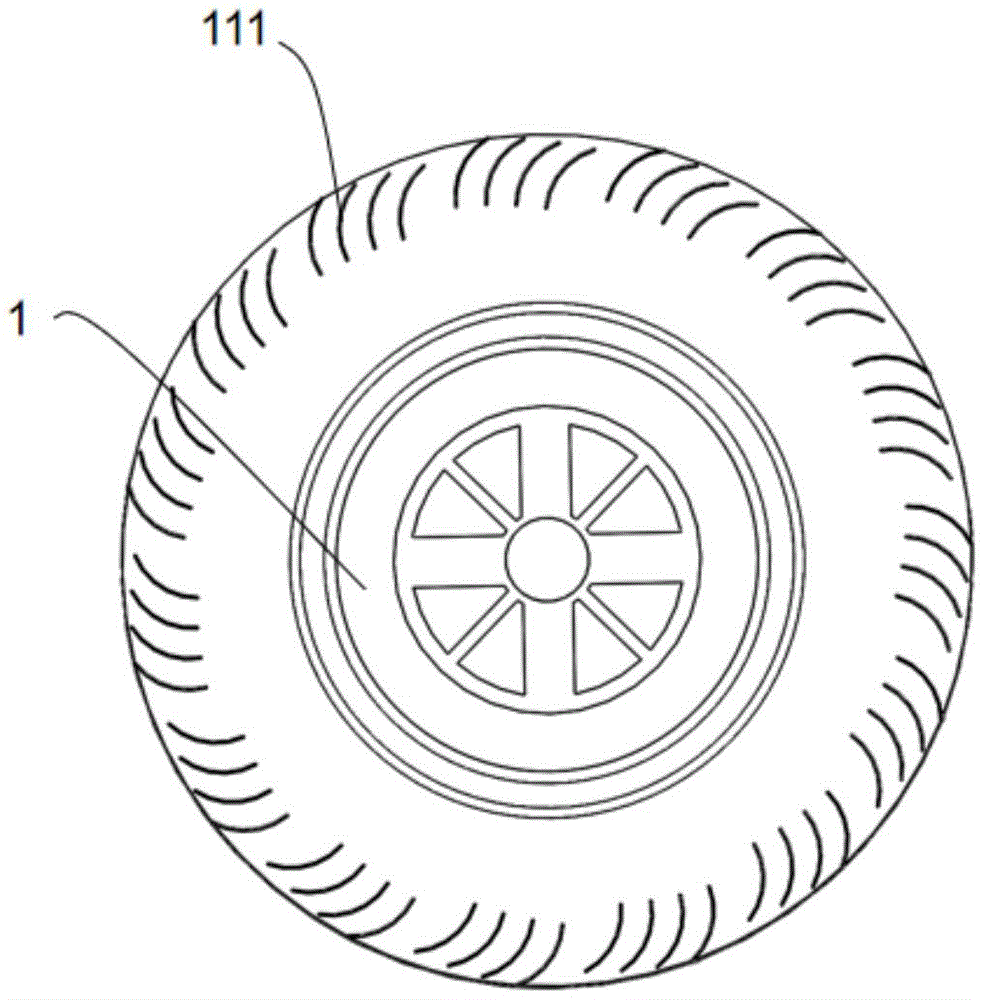
图2是本公开实施例提供的风轮的整体结构示意图;Fig. 2 is a schematic diagram of the overall structure of the wind wheel provided by the embodiment of the present disclosure;
图3是本公开实施例提供的离心风机的整体结构示意图;Fig. 3 is a schematic diagram of the overall structure of a centrifugal fan provided by an embodiment of the present disclosure;
图4是本公开实施例提供的油烟机的局部结构示意图。Fig. 4 is a schematic diagram of a partial structure of a range hood provided by an embodiment of the present disclosure.
附图标记:Reference signs:
1:风轮;11:第一叶轮;12:第二叶轮;111:叶片;13:叶轮座;131:传动轴;14:第一边盘;15:第二边盘;1: wind wheel; 11: first impeller; 12: second impeller; 111: blade; 13: impeller seat; 131: transmission shaft; 14: first side plate; 15: second side plate;
2:蜗壳;21:蜗壳出风口;2: volute; 21: air outlet of volute;
3:驱动电机;3: drive motor;
4:固定支架;41:固定座;42:支撑梁;4: fixed bracket; 41: fixed seat; 42: support beam;
5:环形钣金件;5: Ring sheet metal parts;
6:箱体。6: Box body.
具体实施方式Detailed ways
为了能够更加详尽地了解本公开实施例的特点与技术内容,下面结合附图对本公开实施例的实现进行详细阐述,所附附图仅供参考说明之用,并非用来限定本公开实施例。在以下的技术描述中,为方便解释起见,通过多个细节以提供对所披露实施例的充分理解。然而,在没有这些细节的情况下,一个或多个实施例仍然可以实施。在其它情况下,为简化附图,熟知的结构和装置可以简化展示。In order to understand the characteristics and technical content of the embodiments of the present disclosure in more detail, the implementation of the embodiments of the present disclosure will be described in detail below in conjunction with the accompanying drawings. The attached drawings are only for reference and description, and are not intended to limit the embodiments of the present disclosure. In the following technical description, for purposes of explanation, numerous details are set forth in order to provide a thorough understanding of the disclosed embodiments. However, one or more embodiments may be practiced without these details. In other instances, well-known structures and devices may be shown simplified in order to simplify the drawings.
本公开实施例的说明书和权利要求书及上述附图中的术语“第一”、“第二”等是用于区别类似的对象,而不必用于描述特定的顺序或先后次序。应该理解这样使用的数据在适当情况下可以互换,以便这里描述的本公开实施例的实施例。此外,术语“包括”和“具有”以及他们的任何变形,意图在于覆盖不排他的包含。The terms "first", "second" and the like in the description and claims of the embodiments of the present disclosure and the above drawings are used to distinguish similar objects, and are not necessarily used to describe a specific sequence or sequence. It should be understood that the data so used may be interchanged under appropriate circumstances so as to facilitate the embodiments of the disclosed embodiments described herein. Furthermore, the terms "comprising" and "having", as well as any variations thereof, are intended to cover a non-exclusive inclusion.
本公开实施例中,术语“上”、“下”、“内”、“中”、“外”、“前”、“后”等指示的方位或位置关系为基于附图所示的方位或位置关系。这些术语主要是为了更好地描述本公开实施例及其实施例,并非用于限定所指示的装置、元件或组成部分必须具有特定方位,或以特定方位进行构造和操作。并且,上述部分术语除了可以用于表示方位或位置关系以外,还可能用于表示其他含义,例如术语“上”在某些情况下也可能用于表示某种依附关系或连接关系。对于本领域普通技术人员而言,可以根据具体情况理解这些术语在本公开实施例中的具体含义。In the embodiments of the present disclosure, the orientations or positional relationships indicated by the terms "upper", "lower", "inner", "middle", "outer", "front", "rear" etc. are based on the orientations or positional relationships shown in the drawings. Positional relationship. These terms are mainly used to better describe the embodiments of the present disclosure and their implementations, and are not used to limit that the indicated devices, elements or components must have a specific orientation, or be constructed and operated in a specific orientation. Moreover, some of the above terms may be used to indicate other meanings besides orientation or positional relationship, for example, the term "upper" may also be used to indicate a certain attachment relationship or connection relationship in some cases. Those skilled in the art can understand the specific meanings of these terms in the embodiments of the present disclosure according to specific situations.
另外,术语“设置”、“连接”、“固定”应做广义理解。例如,“连接”可以是固定连接,可拆卸连接,或整体式构造;可以是机械连接,或电连接;可以是直接相连,或者是通过中间媒介间接相连,又或者是两个装置、元件或组成部分之间内部的连通。对于本领域普通技术人员而言,可以根据具体情况理解上述术语在本公开实施例中的具体含义。In addition, the terms "setting", "connecting" and "fixing" should be interpreted broadly. For example, "connection" can be a fixed connection, a detachable connection, or an integral structure; it can be a mechanical connection, or an electrical connection; it can be a direct connection, or an indirect connection through an intermediary, or two devices, components or Internal connectivity between components. Those skilled in the art can understand the specific meanings of the above terms in the embodiments of the present disclosure according to specific situations.
除非另有说明,术语“多个”表示两个或两个以上。Unless stated otherwise, the term "plurality" means two or more.
本公开实施例中,字符“/”表示前后对象是一种“或”的关系。例如,A/B表示:A或B。In the embodiments of the present disclosure, the character "/" indicates that the preceding and following objects are an "or" relationship. For example, A/B means: A or B.
术语“和/或”是一种描述对象的关联关系,表示可以存在三种关系。例如,A和/或B,表示:A或B,或,A和B这三种关系。The term "and/or" is an associative relationship describing objects, indicating that there can be three relationships. For example, A and/or B means: A or B, or, A and B, these three relationships.
需要说明的是,在不冲突的情况下,本公开实施例中的实施例及实施例中的特征可以相互组合。It should be noted that, in the case of no conflict, the embodiments and the features in the embodiments of the present disclosure may be combined with each other.
结合图1-4所示,本公开实施例提供一种离心风机包括蜗壳2和风轮1。蜗壳2两侧开设有进风口;风轮1位于蜗壳2内,风轮1包括若干呈非圆周对称分布的叶片111,风轮1出口角大于90°。As shown in FIGS. 1-4 , an embodiment of the present disclosure provides a centrifugal fan including a
目前现有的离心风机,其风轮1为中比转速,风量大风压较小,仅适合于对流动分离有要求及提升风机效率的场景。除风压有限外,其风轮1旋转过程中会引起离散噪声,不适用于油烟机及集成灶使用,风压无法满足矮楼层烟道长,阻力较大的应用场景。At present, the existing centrifugal fan has a medium specific speed of the
本申请中的离心风机,蜗壳2内设置前置离心风轮1,蜗壳2将离开风轮1的气体导向蜗壳出风口21,并将气体的一部分动能转变为静压,在不减小风量的前提下,能够改善风压过小的问题。此外,非圆周对称分布的叶片111,使离心风机的离散噪声得以改善,流量风压值提高2%-5%。In the centrifugal fan in this application, the front
可选地,风轮1中的叶片111划分为多组叶片111组,相邻叶片111组间间距大于同组叶片111间距。Optionally, the
相邻叶片111组之间的间隙能够对气流进行分流,有效抑制分离涡的产生。当气体从蜗壳2两侧进风口进入离心风机,叶片111组间间隙能够破坏涡流,有效提高离心风机的静压效率。The gaps between adjacent sets of
此外,风轮1组间间距大于叶片111间距,能够在一定程度上削减蜗壳2内的二次流动,从而使离心风轮1能够获得更好的整流效果。In addition, the distance between groups of
可选地,风轮1包括叶轮组件和边盘组件。叶轮组件包括固定设置在叶轮座13两侧的第一叶轮11和第二叶轮12,第一叶轮11和第二叶轮12均包括多组叶片111组;边盘组件包括第一边盘14和第二边盘15,第一叶轮11两端分别固定连接在叶轮座13和第一边盘14上,第二叶轮12两端分别固定连接在叶轮座13和第二边盘15上。Optionally, the
可选地,第一边盘14、叶轮座13和第二边盘15依次间隔排布,第一边盘14和第二边盘15为圆环形。第一边盘14和第二边盘15均开设有多个插接孔,多个插接孔用于与多个叶片111插接配合,多个插接孔沿叶轮座13周向间隔设置,从而提高了风轮1在转动过程中的平衡性能。Optionally, the
可选地,第一边盘14和第二边盘15的内环面均设置有加强筋。Optionally, the inner ring surfaces of the
加强筋改变了风轮1的模态,提高了风轮1的强度,使得风轮1能够满足高速转动工况下的强度需求,提高了风轮1的使用寿命。此外,加强筋还能够避免风轮1的径向跳动,提高了风轮1的安全性能。The ribs change the mode of the
可选地,第一叶轮11和第二叶轮12基于叶轮座13对称分布。这样,能够保证风轮1转动过程中的平衡性能。Optionally, the
可选地,叶片111上在轴向宽度上开设有多段式开缝。Optionally, the
具体地,每个叶片111在叶片111内径和外径之间进行开缝处理,每个叶片111的开缝数量为多个,多个开缝呈一字型间隔排布。Specifically, each
风轮1转动过程中,部分空气通过多个开缝进入叶片111间,在风轮1上形成多个气流补给流道,大大降低了叶片111间的流动分离,使得风机风量有了显著的提升。During the rotation of the
可选地,开缝15缝宽范围在0.5mm至5mm内。Optionally, the width of the
具体地,开缝15缝宽可以选择0.5mm、1mm、1.5mm、2mm、2.5mm、3mm、3.5mm、4mm、4.5mm和5mm。优选地,开缝15缝宽为2mm或3mm。使用本申请中的风轮1能够更好地降低风损和风噪。Specifically, the width of the
可选地,蜗壳2两侧均设置有进风口,第一叶轮11和第二叶轮12的叶片111错齿布置。Optionally, both sides of the
蜗壳2两侧进风增大了进风面积,错齿布置能够缓解离散噪声,使得噪声峰值控制在0.5dB至1dB范围内。The air intake on both sides of the
可选地,叶片111组的叶片111数量范围为[4,6]。Optionally, the number of
具体地,离心风机的总叶片111数范围为[50,70],叶片111组的叶片111数量范围为[4,6],经模拟测试,此种含非对称风轮1分布的前置离心风机,能够获得更适配的流量风压,更好地解决矮楼层风道阻力过大的问题。其中,离心风机的总片数可以为50、54、55、56、58、60、65、70片等等,叶片111组的叶片111数可以为4、5和6片。优选地,离心风机的总叶片111数为60片,每组叶片111组的叶片111数量为5片。Specifically, the range of the total number of
可选地,叶片111的圆心角范围为[14°,20°]。具体地,圆心角的可以选取14°、16°、17°、18°、19°、20°等等。优选地,圆心角度为17°或18°。Optionally, the central angle range of the
具体地,圆心角设置在[14°,20°]的范围内,风轮1出口角范围为[140°,175°]。能够使得离心风机获得前向离心力及低比转速,使得离心风机在不减小风量的前提下,改善风压过小的问题。其中,风轮1出口角可以选择140°、145°、150°、155°、165°、170°、175°等等。优选地,风轮1出口角度为160°或165°。Specifically, the center angle is set within the range of [14°, 20°], and the range of the outlet angle of the
可选地,离心风轮1的外径与内径的比值范围为[1.01,1.03]。Optionally, the ratio of the outer diameter to the inner diameter of the
具体地,外径和内径的比值可选择1.01、1、1.02和1.03。这样,能够利于将离开风轮1的气体导向蜗壳出风口21,将气体的一部分动能转变为静压。Specifically, the ratio of the outer diameter to the inner diameter can be selected as 1.01, 1, 1.02 and 1.03. In this way, the gas leaving the
可选地,第一叶轮11和第二叶轮12的叶片111数量相等。第一叶轮11和第二叶轮12以相同数量对称分布在叶轮座13两侧,能够使风轮1具有良好的动平衡性能。Optionally, the number of
可选地,叶片111、叶轮座13和边盘组件一体成型;或,叶片111和叶轮座13一体成型。Optionally, the
具体地,叶片111、叶轮座13和边盘组件一体成型的成型方式,能够提高整体结构强度,降低装配难度,提高装配效率。Specifically, the integral molding of the
叶片111和叶轮座13一体成型,能够避免叶片111相对叶轮座13发生径向偏移震动,提高转动稳定性,降低叶片111转动时的噪音。叶片111与边盘组件可拆卸连接,能够更好地对零部件进行维护保养或更换。The integral molding of the
可选地,各个叶片111尺寸相同,且均为横截面为弧形的长条形结构。其中,弧形叶片111可以为圆弧形叶片111或机翼形叶片111。Optionally, the
可选地,离心风机还包括固定支架4和驱动电机3。固定支架4固定在蜗壳2进风口侧;驱动电机3固定在固定支架4上,驱动电机3的驱动输出端与叶轮座13圆心处的传动轴131连接。Optionally, the centrifugal fan also includes a fixed
驱动电机3运行,其驱动输出端能够带动与其传动连接的风轮1旋转。将驱动电机3设置于蜗壳2进风口侧,能够提高驱动电机3的散热效率,防止驱动电机3长期工作发生热损,影响使用寿命。The driving
可选地,固定支架4包括固定座41和支架组件。驱动电机3设置在固定座41上;支架组件包括两个或多个支撑梁42,支撑梁42一端固定在蜗壳2进风口的边沿处,支撑梁42另一端连接固定座41。Optionally, the fixing
具体地,驱动电机3设置于蜗壳2进风口的中部,相邻支撑梁42之间形成蜗壳2进风区域。这样,能够使气流从驱动电机3的外围进入蜗壳2,更好地对驱动电机3散热,同时又不会影响离心风机的进风风量,也能够更好地利用空间。Specifically, the driving
可选地,支撑梁42由蜗壳2进风口向叶轮座13倾斜,以使驱动电机3位于蜗壳2的空间内。Optionally, the
通过支撑梁42使驱动电机3位于蜗壳2空间内,一方面,能够使驱动电机3获得更大风量的气流流过,提高散热效率;另一方面,支撑梁42能够提高蜗壳2的强度,对蜗壳出风口21起到一定支撑作用,防止蜗壳2变形。The
可选地,离心风机还包括环形钣金件5,环形钣金件5套设在蜗壳出风口21处。离心风机进风口侧安装有驱动电机3,蜗壳出风口21在重力作用以及为驱动电机3提供承载力的情况下,极易变形,通过设置环形钣金件5,能够加固蜗壳出风口21,更好地防止蜗壳出风口21变形。Optionally, the centrifugal fan further includes an annular
可选地,风轮1的材质为塑料材质。Optionally, the material of the
相对于金属材质的风轮1,使用塑料制风轮1,能够更大风量、更小噪音。Compared with the
本公开实施例提供一种油烟机,油烟机包括前述的离心风机。油烟机风道内的离心风机设置前置离心风轮1,蜗壳2将离开风轮1的气体导向蜗壳出风口21,并将气体的一部分动能转变为静压,在不减小风量的前提下,能够改善风压过小的问题。此外,非圆周对称分布的叶片111,使离心风机的离散噪声得以改善,流量风压值提高2%-5%。An embodiment of the present disclosure provides a range hood, which includes the foregoing centrifugal fan. The centrifugal fan in the range hood air duct is equipped with a front
可选地,蜗壳2包括第一进风口和第二进风口,第一进风口为靠近油烟机后背板的一侧,第二进风口为靠近油烟机前面板的一侧。驱动电机3固定在第一进风口侧。Optionally, the
这样,一方面能够使更多油烟通过第一进风口进入蜗壳2内,减少油烟附着在驱动电机3上,提高元件使用寿命。In this way, on the one hand, more oil fume can enter the
可选地,油烟机还包括箱体6,箱体6位于油烟机内,箱体6进风口设于油烟机的吸风口处,蜗壳出风口21卡设固定在箱体6的出风口,箱体6出风口通过排烟管与外部相通。Optionally, the range hood also includes a
可以理解的,箱体6的设置能够避免油烟扩散到整个油烟机内,箱体6相当于风道,含有油烟的气流通过油烟机吸风口吸入后,经过箱体6引流进入蜗壳2内,之后通过排烟管排至室外。It can be understood that the setting of the
以上描述和附图充分地示出了本公开的实施例,以使本领域的技术人员能够实践它们。其他实施例可以包括结构的以及其他的改变。实施例仅代表可能的变化。除非明确要求,否则单独的部件和功能是可选的,并且操作的顺序可以变化。一些实施例的部分和特征可以被包括在或替换其他实施例的部分和特征。本公开的实施例并不局限于上面已经描述并在附图中示出的结构,并且可以在不脱离其范围进行各种修改和改变。本公开的范围仅由所附的权利要求来限制。The above description and drawings sufficiently illustrate the embodiments of the present disclosure to enable those skilled in the art to practice them. Other embodiments may incorporate structural and other changes. The examples merely represent possible variations. Individual components and functions are optional unless explicitly required, and the order of operations may vary. Portions and features of some embodiments may be included in or substituted for those of other embodiments. Embodiments of the present disclosure are not limited to the structures that have been described above and shown in the drawings, and various modifications and changes may be made without departing from the scope thereof. The scope of the present disclosure is limited only by the appended claims.
Claims (10)
Priority Applications (1)
| Application Number | Priority Date | Filing Date | Title |
|---|---|---|---|
| CN202223076620.2U CN219220822U (en) | 2022-11-18 | 2022-11-18 | Centrifugal fan and range hood |
Applications Claiming Priority (1)
| Application Number | Priority Date | Filing Date | Title |
|---|---|---|---|
| CN202223076620.2U CN219220822U (en) | 2022-11-18 | 2022-11-18 | Centrifugal fan and range hood |
Publications (1)
| Publication Number | Publication Date |
|---|---|
| CN219220822U true CN219220822U (en) | 2023-06-20 |
Family
ID=86749656
Family Applications (1)
| Application Number | Title | Priority Date | Filing Date |
|---|---|---|---|
| CN202223076620.2U Expired - Fee Related CN219220822U (en) | 2022-11-18 | 2022-11-18 | Centrifugal fan and range hood |
Country Status (1)
| Country | Link |
|---|---|
| CN (1) | CN219220822U (en) |
Cited By (1)
| Publication number | Priority date | Publication date | Assignee | Title |
|---|---|---|---|---|
| CN117167302A (en) * | 2023-09-20 | 2023-12-05 | 成都前锋电子有限责任公司 | Low-rotation-speed large-air-volume volute assembly and smoke exhaust ventilator thereof |
-
2022
- 2022-11-18 CN CN202223076620.2U patent/CN219220822U/en not_active Expired - Fee Related
Cited By (1)
| Publication number | Priority date | Publication date | Assignee | Title |
|---|---|---|---|---|
| CN117167302A (en) * | 2023-09-20 | 2023-12-05 | 成都前锋电子有限责任公司 | Low-rotation-speed large-air-volume volute assembly and smoke exhaust ventilator thereof |
Similar Documents
| Publication | Publication Date | Title |
|---|---|---|
| US10052931B2 (en) | Outdoor cooling unit in vehicle air-conditioning apparatus | |
| WO2022143328A1 (en) | Centrifugal fan, household appliance, volute, and cooking utensil | |
| CN109404305B (en) | Bionic blade volute-free centrifugal ventilator | |
| CN111927823B (en) | A centrifugal impeller and a high specific speed energy-saving centrifugal dust removal fan | |
| CN209569902U (en) | Gas water heater | |
| CN113685371B (en) | A motor fan impeller | |
| JP2701604B2 (en) | Air conditioner | |
| CN107906046A (en) | A kind of blast fan | |
| CN115773279A (en) | Long and short blade type impeller and centrifugal fan | |
| CN103016369B (en) | A New Type Axial Flow Fan with Small Aspect Ratio Blade Root Obliquely Cut and Twisted Blades | |
| CN109931289A (en) | A kind of vaneless diffuser of Voluteless fan | |
| CN206419268U (en) | One kind energy-conservation hypsokinesis wind wheel | |
| CN108869392A (en) | Composite impeller, centrifugal fan and range hood | |
| CN202883468U (en) | Floor-stand air conditioner and oblique flow fan thereof | |
| CN212431079U (en) | Air duct machine | |
| CN210769382U (en) | High-efficient mixed flow fan | |
| CN202789616U (en) | Axial centrifugal fan | |
| CN100353077C (en) | air outlet structure of axial flow fan | |
| WO2022191034A1 (en) | Propeller fan and refrigeration device | |
| CN222863675U (en) | Impeller, fan and range hood | |
| CN222810982U (en) | Impeller structure, fan and range hood | |
| CN223814183U (en) | Wind wheel, fresh air module and air conditioner | |
| CN222351009U (en) | Impellers, centrifugal fans and range hoods | |
| CN219654913U (en) | Circular centrifugal axial flow fan | |
| CN218862926U (en) | Impeller of multi-wing centrifugal fan, multi-wing centrifugal fan and range hood |
Legal Events
| Date | Code | Title | Description |
|---|---|---|---|
| GR01 | Patent grant | ||
| GR01 | Patent grant | ||
| CF01 | Termination of patent right due to non-payment of annual fee | ||
| CF01 | Termination of patent right due to non-payment of annual fee |
Granted publication date: 20230620 |