CN219209907U - A self-cleaning solvent-free polyurethane mixing equipment - Google Patents
A self-cleaning solvent-free polyurethane mixing equipment Download PDFInfo
- Publication number
- CN219209907U CN219209907U CN202320806672.6U CN202320806672U CN219209907U CN 219209907 U CN219209907 U CN 219209907U CN 202320806672 U CN202320806672 U CN 202320806672U CN 219209907 U CN219209907 U CN 219209907U
- Authority
- CN
- China
- Prior art keywords
- kettle body
- kettle
- storage tank
- filter
- self
- Prior art date
- Legal status (The legal status is an assumption and is not a legal conclusion. Google has not performed a legal analysis and makes no representation as to the accuracy of the status listed.)
- Active
Links
Images

Classifications
-
- Y—GENERAL TAGGING OF NEW TECHNOLOGICAL DEVELOPMENTS; GENERAL TAGGING OF CROSS-SECTIONAL TECHNOLOGIES SPANNING OVER SEVERAL SECTIONS OF THE IPC; TECHNICAL SUBJECTS COVERED BY FORMER USPC CROSS-REFERENCE ART COLLECTIONS [XRACs] AND DIGESTS
- Y02—TECHNOLOGIES OR APPLICATIONS FOR MITIGATION OR ADAPTATION AGAINST CLIMATE CHANGE
- Y02P—CLIMATE CHANGE MITIGATION TECHNOLOGIES IN THE PRODUCTION OR PROCESSING OF GOODS
- Y02P70/00—Climate change mitigation technologies in the production process for final industrial or consumer products
- Y02P70/10—Greenhouse gas [GHG] capture, material saving, heat recovery or other energy efficient measures, e.g. motor control, characterised by manufacturing processes, e.g. for rolling metal or metal working
Landscapes
- Accessories For Mixers (AREA)
Abstract
本技术方案公开了一种自清洁无溶剂聚氨酯搅拌设备,包括釜体和第一固定板;第一固定板上方连接有第二固定板,第二固定板顶部一侧固定安装有加热器;加热器内侧连接有釜体,釜体上设有温度传感器,温度传感器连接在搅拌釜体的外侧,且温度传感器的测温端穿设进釜体内;釜体顶部安装有釜盖,釜盖顶部密封设置连接板,连接板上配置有搅拌电机,搅拌电机的搅拌轴延伸于釜体内;釜体下方连接有阀门,阀门通过管路连接有过滤器,过滤器通过管路连接有粘度泵。本技术方案解决目前无溶剂工艺中需要配套的加热及及时清洁的问题。
The technical solution discloses a self-cleaning solvent-free polyurethane stirring device, which includes a kettle body and a first fixed plate; a second fixed plate is connected above the first fixed plate, and a heater is fixedly installed on the top side of the second fixed plate; The inner side of the kettle is connected with a kettle body, and a temperature sensor is arranged on the kettle body, and the temperature sensor is connected to the outside of the stirred kettle body, and the temperature measuring end of the temperature sensor is penetrated into the kettle body; a kettle cover is installed on the top of the kettle body, and the top of the kettle cover is sealed A connecting plate is provided, and a stirring motor is arranged on the connecting plate, and the stirring shaft of the stirring motor extends in the kettle body; a valve is connected under the kettle body, the valve is connected to a filter through a pipeline, and the filter is connected to a viscosity pump through a pipeline. The technical solution solves the problems of matching heating and timely cleaning in the current solvent-free process.
Description
技术领域technical field
本实用新型涉及聚氨酯生产设备,具体涉及一种自清洁无溶剂聚氨酯搅拌设备。The utility model relates to polyurethane production equipment, in particular to a self-cleaning solvent-free polyurethane stirring equipment.
背景技术Background technique
目前,常用的聚氨酯树脂是利用异氰酸酯和多元醇等作为原料合成大分子聚合物溶解分散在有机溶剂中,通过烘干或水浴凝固等方式在基材表面成型,从而得到一系列产品。这类产品的污染较为严重,存在DMF等有机溶剂挥发污染环境等问题,后来有研究者开发了一种基于原位合成法的无溶剂聚氨酯树脂产品,能够在短时间内快速固化且无溶剂释放,是一种高效环保型产品。随着这类产品在市场上应用越来越广泛,亟需一种适用的对应的无溶剂聚氨酯的搅拌釜设备。At present, the commonly used polyurethane resin is to use isocyanate and polyol as raw materials to synthesize macromolecular polymers, dissolve and disperse them in organic solvents, and form them on the surface of substrates by drying or water bath coagulation, so as to obtain a series of products. The pollution of such products is relatively serious, and there are problems such as the volatilization of organic solvents such as DMF to pollute the environment. Later, some researchers developed a solvent-free polyurethane resin product based on in-situ synthesis method, which can be quickly cured in a short time and released without solvents. , is an efficient and environmentally friendly product. As such products are more and more widely used in the market, there is an urgent need for a suitable and corresponding solvent-free polyurethane stirred tank equipment.
现有的聚氨酯搅拌反应釜只能对聚氨酯原料起到搅拌分散作用,功能较为单一,而无溶剂工艺需要对原料进行控温处理,同时反应完成以后釜体也需及时清洁,否则容易影响成品质量以及在釜体表面形成结块影响后续生产。The existing polyurethane stirring reactor can only stir and disperse the polyurethane raw material, and its function is relatively single, while the solvent-free process needs to control the temperature of the raw material, and at the same time, the kettle body needs to be cleaned in time after the reaction is completed, otherwise it will easily affect the quality of the finished product And the formation of agglomerates on the surface of the kettle affects subsequent production.
为了避免上述情况,目前急需一种搅拌设备能解决上述问题。In order to avoid the above-mentioned situation, there is an urgent need for a stirring device that can solve the above-mentioned problems.
实用新型内容Utility model content
本实用新型的目的是提供一种自清洁无溶剂聚氨酯搅拌设备,解决目前无溶剂工艺中需要配套的加热及及时清洁的问题。The purpose of the utility model is to provide a self-cleaning solvent-free polyurethane stirring equipment, which solves the problems of matching heating and timely cleaning in the current solvent-free process.
一种自清洁无溶剂聚氨酯搅拌设备,包括釜体和第一固定板;第一固定板上方连接有第二固定板,第二固定板顶部一侧固定安装有加热器;加热器内侧连接有釜体,釜体上设有温度传感器,温度传感器连接在搅拌釜体的外侧,且温度传感器的测温端穿设进釜体内;釜体顶部安装有釜盖,釜盖顶部密封设置连接板,连接板上配置有搅拌电机,搅拌电机的搅拌轴延伸于釜体内;釜体下方连接有阀门,阀门通过管路连接有过滤器,过滤器通过管路连接有粘度泵,粘度泵连接有延伸至回收储罐的输入管,输入管外侧安装有滴液喷头,第二固定板另一侧安装有回收储罐和清洗液储罐。A self-cleaning solvent-free polyurethane stirring device, including a kettle body and a first fixed plate; a second fixed plate is connected above the first fixed plate, and a heater is fixedly installed on the top side of the second fixed plate; a kettle is connected inside the heater Body, the kettle body is provided with a temperature sensor, the temperature sensor is connected to the outside of the stirring kettle body, and the temperature measuring end of the temperature sensor is penetrated into the kettle body; There is a stirring motor on the board, and the stirring shaft of the stirring motor extends in the kettle body; a valve is connected to the bottom of the kettle body, and the valve is connected to a filter through a pipeline, and the filter is connected to a viscosity pump through a pipeline, and the viscosity pump is connected to an extension to the recovery The input pipe of the storage tank is provided with a drip nozzle on the outside of the input pipe, and a recovery storage tank and a cleaning liquid storage tank are installed on the other side of the second fixing plate.
所述釜体左侧安装有环形喷头,且环形喷头通过螺栓安装有输送管,输送管延伸至釜体侧部并固定连接有三通切换阀。An annular nozzle is installed on the left side of the kettle body, and the annular nozzle is equipped with a conveying pipe through bolts, and the conveying pipe extends to the side of the kettle body and is fixedly connected with a three-way switching valve.
所述釜体右侧安装脱气口,脱气口外固定连接有软管,该软管连接抽气装置。A degassing port is installed on the right side of the kettle body, and a hose is fixedly connected to the outside of the degassing port, and the hose is connected to an air extraction device.
所述清洗液储罐内部配置有机清洗液,清洗液储罐顶部设置有泵体,且泵体的输出端与三通切换阀的一个端口连通,三通切换阀的另一端口与回收储罐顶部的泵体相连通。The inside of the cleaning liquid storage tank is equipped with an organic cleaning liquid, the top of the cleaning liquid storage tank is provided with a pump body, and the output end of the pump body is connected to one port of the three-way switching valve, and the other port of the three-way switching valve is connected to the recovery storage tank. The pump body at the top is connected.
所述过滤器包括筒体、过滤网和排污组件;筒体上端通过管路连接有排污泵,筒体输入端通过螺丝固定连接有固定螺环,固定螺环内固定连接有过滤网,过滤网采用有机系过滤膜材料,筒体下端通过螺栓连接有排污组件,筒体侧表面固定连接有电器控制箱。The filter includes a cylinder body, a filter screen and a sewage discharge assembly; the upper end of the cylinder body is connected to a sewage pump through a pipeline, and the input end of the cylinder body is fixedly connected to a fixed spiral ring through a screw, and a filter screen is fixedly connected to the fixed spiral ring, and the filter screen The organic filter membrane material is used, the lower end of the cylinder body is connected with a sewage assembly through bolts, and the side surface of the cylinder body is fixedly connected with an electrical control box.
本实用新型的有益效果是:The beneficial effects of the utility model are:
1.本实用新型通过在釜体下方管道安装过滤器,有利于对清洗液中固化物进行过滤,保障清洗液顺利流入回收储罐,并且有利于回收液对釜体的循环清洁。1. The utility model installs a filter in the pipeline under the kettle body, which is beneficial to filter the solidified matter in the cleaning liquid, ensures that the cleaning liquid flows smoothly into the recovery storage tank, and is conducive to the recycling of the recovery liquid to the kettle body.
2.本实用新型通过在第二固定板另一侧安装回收储罐和清洗液储罐,利用三通切换阀、过滤器和粘度泵等可以使清洗液对反应釜进行循环清洗,提高了反应釜的清洗效率,同时避免有机清洗液挥发所导致的环境污染问题,保障了无溶剂聚氨酯原料生产的质量与安全。2. The utility model installs a recovery storage tank and a cleaning liquid storage tank on the other side of the second fixed plate, and uses a three-way switching valve, a filter and a viscosity pump to make the cleaning liquid circulate and clean the reactor, which improves the reaction rate. The cleaning efficiency of the kettle is improved, and the environmental pollution caused by the volatilization of the organic cleaning solution is avoided, which ensures the quality and safety of the production of solvent-free polyurethane raw materials.
3.本实用新型通过在釜体侧部设置加热器,釜体内部设置温度传感器,有利于对无溶剂聚氨酯物料反应情况进行调控,同时也便于釜体清洁过后的干燥,提高了生产的效率和设备实用性。3. The utility model is equipped with a heater on the side of the kettle body and a temperature sensor inside the kettle body, which is beneficial to control the reaction of the solvent-free polyurethane material, and at the same time facilitates the drying of the kettle body after cleaning, improving the production efficiency and Equipment availability.
附图说明Description of drawings
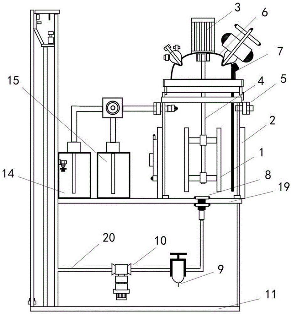
图1为本实用新型的结构示意图;Fig. 1 is the structural representation of the utility model;
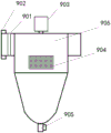
图2为本实用新型的过滤器结构示意图;Fig. 2 is the structural representation of filter of the present utility model;
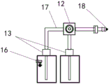
图3为本实用新型的清洗组件结构示意图;Fig. 3 is the structural representation of the cleaning assembly of the utility model;
图中:1.釜体、2.加热器、3.搅拌电机、4.搅拌轴、5.脱气口、6.釜盖、7.温度传感器、8.阀门、9.过滤器、901.过滤网、902.固定螺环、903.排污泵、904.电器控制箱、905.排污组件、906.筒体、10.粘度泵、11.第一固定板、12.三通切换阀、13.泵体、14.回收储罐、15.清洗液储罐、16.滴液喷头、17.输送管、18.环形喷头、19.第二固定板、20.输入管。In the figure: 1. Kettle body, 2. Heater, 3. Stirring motor, 4. Stirring shaft, 5. Degassing port, 6. Kettle cover, 7. Temperature sensor, 8. Valve, 9. Filter, 901. Filtration Net, 902. Fixed screw ring, 903. Sewage pump, 904. Electrical control box, 905. Sewage component, 906. Cylinder, 10. Viscosity pump, 11. First fixed plate, 12. Three-way switching valve, 13. Pump body, 14. Recovery storage tank, 15. Cleaning liquid storage tank, 16. Drop nozzle, 17. Delivery pipe, 18. Ring nozzle, 19. Second fixing plate, 20. Input pipe.
具体实施方式Detailed ways
以下由特定的具体实施例说明本实用新型的实施方式,熟悉此技术的人士可由本说明书所揭露的内容轻易地了解本实用新型的其他优点及功效。须知,本说明书所附图式所绘示的结构、比例、大小等,均仅用以配合说明书所揭示的内容,以供熟悉此技术的人士了解与阅读,并非用以限定本实用新型可实施的限定条件,故不具技术上的实质意义,任何结构的修饰、比例关系的改变或大小的调整,在不影响本实用新型所能产生的功效及所能达成的目的下,均应仍落在本实用新型所揭示的技术内容得能涵盖的范围内。同时,本说明书中所引用的如“上”、“下”、“左”、“右”、“中间”及“一”等的用语,亦仅为便于叙述的明了,而非用以限定本实用新型可实施的范围,其相对关系的改变或调整,在无实质变更技术内容下,当亦视为本实用新型可实施的范畴。The implementation of the present utility model is illustrated by specific specific examples below, and those skilled in the art can easily understand other advantages and effects of the present utility model from the content disclosed in this specification. It should be noted that the structures, proportions, sizes, etc. shown in the drawings attached to this specification are only used to match the content disclosed in the specification, for those who are familiar with this technology to understand and read, and are not used to limit the implementation of the utility model Therefore, it has no technical substantive meaning. Any modification of structure, change of proportional relationship or adjustment of size should still fall within the scope of The technical content disclosed by the utility model must be within the scope covered. At the same time, terms such as "upper", "lower", "left", "right", "middle" and "one" quoted in this specification are only for the convenience of description and are not used to limit this specification. The practicable range of the utility model, and the change or adjustment of its relative relationship, without any substantial change in the technical content, shall also be regarded as the practicable scope of the utility model.
请参阅图1至图3,图中的设备设计了釜体1和第一固定板11以及其它部件,这些部件均可采用现有配件或者根据本案进行适应性的选择。第一固定板11上方连接有第二固定板19,从而得到第一固定板11的固定和支撑,釜体1用于作为反应容器。第二固定板19顶部一侧固定安装有加热器2,加热器2内侧配置在釜体1上。釜体1上同时配置有温度传感器7,温度传感器7利用螺栓连接在搅拌釜体1的外侧,且测温端穿设进釜体1内,从而可以实时监控釜体内物料温度的变化,便于加热器2来调节合成反应的快慢和反应程度;釜体1顶部通过螺栓安装有釜盖6,釜盖6顶部密封配置连接板,搅拌电机3安装于连接板上,其搅拌轴4延伸于搅拌釜体1内完成搅拌工作。釜体1下方连接有阀门8,阀门8通过管路配置有过滤器9,过滤器9通过管路连接有粘度泵10,粘度泵10利用螺栓连接有延伸至回收储罐14的输入管20,输入管20外侧安装有滴液喷头16,从而完成设定的工作;第二固定板19另一侧安装有回收储罐14和清洗液储罐15;其中回收储罐14用于清洗液顺利回收,清洗液储罐15用于作为清洗液的来源。Please refer to Fig. 1 to Fig. 3, the equipment design among the
釜体1左侧安装有环形喷头18,且环形喷头18通过螺栓安装有输送管17,输送管17延伸至釜体1侧部并固定连接有三通切换阀12,输送管17可以将三通切换阀12中的清洗液输送到环形喷头18中喷出,从而对釜体1内的残留杂质进行溶解和清洁。An
釜体1右侧安装脱气口5,脱气口5外固定安装有软管,抽气装置连接着软管,釜体1中气体从软管中排除,从而控制釜体1的水分含量,减少其对物料反应的影响。The
清洗液储罐15内部盛装有有机清洗液,清洗液储罐15顶部设置有泵体13,且泵体13的输出端与三通切换阀12的一个端口贯通形成送料通道,三通切换阀12的另一端口与回收储罐14顶部的泵体13相连通形成回料通道。三通切换阀在转换过程中,有机清洗液可以对釜体实现循环清洁,保障生产的高效和卫生。The inside of the cleaning
过滤器9包括筒体906、过滤网901和排污组件905;筒体906上端通过管路连接有排污泵903,从而将流动速度较慢的物料提高流动速度至排污组件905内,筒体906输入端通过螺丝固定连接有固定螺环902,固定螺环902内固定连接有过滤网901,过滤网901采用有机系过滤膜材料,筒体906下端通过螺栓连接有排污组件905,筒体906侧表面固定连接有电器控制箱904,过滤网901可以对有机清洗液中的固化物进行过滤,保障清洗液顺利流入回收储罐14,方便对釜体1进行循环清洁。The filter 9 includes a
本实施例的具体实施步骤及工作原理是:The specific implementation steps and working principle of this embodiment are:
在使用釜体1时,打开釜盖6将物料倒入其中,利用搅拌装置对其进行搅拌、混合,开启脱气装置从脱气口5中排出釜体1内水蒸汽,同时开启加热器2对其进行加热,加热的温度需要保障反应的进行,保证原料受热均匀,利用温度传感器7来观察并调节物料反应状态,确保物料反应完全。When using the
在使用清洁装置时,清洗液储罐15中倒入有机清洗液,然后开启泵体13将清洗液泵出,清洗液经三通切换阀12和输送管17从环形喷头18中喷出,开启搅拌装置对釜体1进行清洁,打开阀门8,清洗液经过滤器9除去固化物,然后通过粘度泵10和输入管20从滴液喷头16中喷出到达回收储罐14,转换三通切换阀12,开启泵体13,回收液再次从环形喷头18喷出,对釜体1进行循环清洁。When using the cleaning device, pour organic cleaning liquid into the cleaning
上述描述的具体实施例仅仅用以解释本技术方案,并不用于限定本技术方案。在本技术方案的描述中,需要说明的是,术语如“上”、“内”等指示的方位或位置关系为基于附图所示的方位或位置关系,仅是为了便于描述本技术方案和简化描述,而不是指示或暗示所指的装置或元件必须具有特定的方位、以特定的方位构造和操作,因此不能理解为对本技术方案的限制。The specific embodiments described above are only used to explain the technical solution, and are not intended to limit the technical solution. In the description of this technical solution, it should be noted that the orientation or positional relationship indicated by terms such as "upper" and "inner" are based on the orientation or positional relationship shown in the drawings, and are only for the convenience of describing the technical solution and Simplified descriptions do not indicate or imply that the referred device or element must have a specific orientation, be constructed and operated in a specific orientation, and therefore should not be construed as limiting the technical solution.
同时,在本技术方案的描述中,需要说明的是,除非另有明确的规定和限定,术语“固定”、“配合”、应做广义理解,例如,可以是固定连接,也可以是可拆卸连接,或一体地连接;可以是直接相连,也可以通过中间媒介间接相连,可以是两个元件内部的连通或两个元件的相互作用关系。对于本领域的普通技术人员而言,可以根据具体情况理解上述术语在本技术方案中的具体含义。At the same time, in the description of this technical solution, it should be noted that, unless otherwise clearly specified and limited, the terms "fixed" and "fit" should be understood in a broad sense, for example, it can be a fixed connection or a detachable connection. Connected, or integrally connected; it can be directly connected or indirectly connected through an intermediary, and it can be the internal communication of two elements or the interaction relationship between two elements. Those of ordinary skill in the art can understand the specific meanings of the above terms in this technical solution according to specific situations.
尽管已经示出和描述了本技术方案的实施例,对于本领域的普通技术人员而言,可以理解在不脱离本技术方案的原理和精神的情况下可以对这些实施例进行多种变化、修改、替换和变型,本技术方案的范围由所附权利要求及其等同物限定。Although the embodiments of the technical solution have been shown and described, those skilled in the art can understand that various changes and modifications can be made to these embodiments without departing from the principle and spirit of the technical solution , replacement and modification, the scope of the technical solution is defined by the appended claims and their equivalents.
Claims (5)
Priority Applications (1)
| Application Number | Priority Date | Filing Date | Title |
|---|---|---|---|
| CN202320806672.6U CN219209907U (en) | 2023-04-12 | 2023-04-12 | A self-cleaning solvent-free polyurethane mixing equipment |
Applications Claiming Priority (1)
| Application Number | Priority Date | Filing Date | Title |
|---|---|---|---|
| CN202320806672.6U CN219209907U (en) | 2023-04-12 | 2023-04-12 | A self-cleaning solvent-free polyurethane mixing equipment |
Publications (1)
| Publication Number | Publication Date |
|---|---|
| CN219209907U true CN219209907U (en) | 2023-06-20 |
Family
ID=86752901
Family Applications (1)
| Application Number | Title | Priority Date | Filing Date |
|---|---|---|---|
| CN202320806672.6U Active CN219209907U (en) | 2023-04-12 | 2023-04-12 | A self-cleaning solvent-free polyurethane mixing equipment |
Country Status (1)
| Country | Link |
|---|---|
| CN (1) | CN219209907U (en) |
-
2023
- 2023-04-12 CN CN202320806672.6U patent/CN219209907U/en active Active
Similar Documents
| Publication | Publication Date | Title |
|---|---|---|
| CN209810133U (en) | Novel silica gel production device | |
| CN204911503U (en) | Primary reaction cauldron | |
| CN206526718U (en) | A kind of raw material agitation mixer of the food factory with heating function | |
| CN209549468U (en) | A reaction kettle for easy cleaning of inner wall agglomeration | |
| CN207549119U (en) | A kind of construction site cement mixer that can be cleared up automatically | |
| CN213101983U (en) | Chemical raw material stirring device | |
| CN209123730U (en) | A kind of quick paint mixing device of aluminium-plastic panel production | |
| CN220573336U (en) | Starch raw material stirring device with cleaning structure | |
| CN203123898U (en) | Multifunctional paint stirrer | |
| CN204196103U (en) | A kind of high-presure polyurethane foaming machine device | |
| CN208229919U (en) | A kind of reaction kettle for high molecular material | |
| CN210045654U (en) | A crystallization rinsing spray set for preparing high-purity β -aminopropionic acid | |
| CN108525564A (en) | A kind of powdery industrial detergent production agitating device | |
| CN219308611U (en) | Mixing device for stripper production and processing | |
| CN219190690U (en) | Fly ash brick compounding briquetting machine | |
| CN218901492U (en) | Efficient stirring formula refining equipment | |
| CN221432832U (en) | Instant dissolving device for liquid detergent production | |
| CN208894071U (en) | A kind of paint mixing device with self-cleaning function | |
| CN220657115U (en) | Sequencing proportioning water-based paint mixing equipment | |
| CN219784467U (en) | Raw material proportioning and mixing device for processing epoxy modified asphalt | |
| CN223959616U (en) | Safety feeding device of solid-liquid-gas three-phase reaction kettle | |
| CN219136407U (en) | Dosing sewage treatment device | |
| CN220576346U (en) | Raw material mixer convenient to clean | |
| CN218890421U (en) | Coating proportioning device | |
| CN221846750U (en) | A mixer for latex paint production |
Legal Events
| Date | Code | Title | Description |
|---|---|---|---|
| GR01 | Patent grant | ||
| GR01 | Patent grant |