CN219204080U - Relay protection setter for distribution network - Google Patents
Relay protection setter for distribution network Download PDFInfo
- Publication number
- CN219204080U CN219204080U CN202223270252.5U CN202223270252U CN219204080U CN 219204080 U CN219204080 U CN 219204080U CN 202223270252 U CN202223270252 U CN 202223270252U CN 219204080 U CN219204080 U CN 219204080U
- Authority
- CN
- China
- Prior art keywords
- sides
- component box
- fixing
- base
- fixedly connected
- Prior art date
- Legal status (The legal status is an assumption and is not a legal conclusion. Google has not performed a legal analysis and makes no representation as to the accuracy of the status listed.)
- Withdrawn - After Issue
Links
Images




Classifications
-
- Y—GENERAL TAGGING OF NEW TECHNOLOGICAL DEVELOPMENTS; GENERAL TAGGING OF CROSS-SECTIONAL TECHNOLOGIES SPANNING OVER SEVERAL SECTIONS OF THE IPC; TECHNICAL SUBJECTS COVERED BY FORMER USPC CROSS-REFERENCE ART COLLECTIONS [XRACs] AND DIGESTS
- Y02—TECHNOLOGIES OR APPLICATIONS FOR MITIGATION OR ADAPTATION AGAINST CLIMATE CHANGE
- Y02A—TECHNOLOGIES FOR ADAPTATION TO CLIMATE CHANGE
- Y02A30/00—Adapting or protecting infrastructure or their operation
- Y02A30/14—Extreme weather resilient electric power supply systems, e.g. strengthening power lines or underground power cables
Landscapes
- Switch Cases, Indication, And Locking (AREA)
Abstract
本实用新型涉及配网继电技术领域,且公开了一种配网继电保护整定器,所述底座顶端两侧开设有滑槽,所述底座后侧两端靠近滑槽位置固定焊接有固定块,所述固定块两侧开设有固定孔,所述固定孔内固定卡接有连接杆,所述固定块通过连接杆穿过两侧的固定孔固定连接有防水盖,所述防水盖前段为凸形,且凸出位置两侧开设有连接孔,所述底座顶端开设有检修口所述检修口内固定卡接有开关底板,所述固定螺栓通过固定盖顶端两侧开设的螺纹孔连接元件盒内壁两侧的螺纹槽固定连接固定盖和元件盒,所述元件盒底端两侧固定焊接的滑轨通过滑轨两侧开设的凹槽固定卡接在底座两侧开设的滑槽内,所述底座两侧开设的滑槽与滑轨两侧开设的凹槽尺寸相等。

The utility model relates to the technical field of distribution network relay, and discloses a relay protection regulator for distribution network. Both sides of the top of the base are provided with chutes, and the two ends of the rear side of the base are fixedly welded to the positions close to the chute. There are fixing holes on both sides of the fixing block, and a connecting rod is fixedly clamped in the fixing hole, and the fixing block is fixedly connected with a waterproof cover through the fixing holes on both sides through the connecting rod, and the front part of the waterproof cover It is convex, and there are connecting holes on both sides of the protruding position, an inspection port is opened on the top of the base, and a switch bottom plate is fixedly clamped in the inspection port, and the fixing bolt is connected to the component through the threaded holes on both sides of the top of the fixing cover. The thread grooves on both sides of the inner wall of the box are fixedly connected to the fixed cover and the component box, and the slide rails fixedly welded on both sides of the bottom of the component box are fixedly snapped into the chute opened on both sides of the base through the grooves on both sides of the slide rail. The chute provided on both sides of the base is equal in size to the groove provided on both sides of the slide rail.
Description
技术领域technical field
本实用新型涉及配网继电技术领域,更具体地涉及一种配网继电保护整定器。The utility model relates to the field of distribution network relay technology, in particular to a distribution network relay protection regulator.
背景技术Background technique
随着我国电网的不断发展和各类家电的广泛使用,使得继电保护整定器的使用越来越广泛,继电保护整定器不仅能为电力系统中的电力设备提供重要的安全防护,同时还能够确保电力系统的安全稳健运行,当输电线等接地失败的情况下,继电保护整定器能够及时的切断电力、避免电力设备发生损坏。With the continuous development of my country's power grid and the wide use of various household appliances, the use of relay protection setters is becoming more and more extensive. Relay protection setters can not only provide important safety protection for power equipment in the power system, but also It can ensure the safe and stable operation of the power system. When the grounding of the transmission line fails, the relay protection setter can cut off the power in time to avoid damage to the power equipment.
现如今继电保护整定器大多安装拆卸繁琐,需要打开整定器按照线路安装或者拆卸,同时大部分整定器不具备防水功能,需要单独在外层安装防水隔板操作安装或者拆卸都很不便捷。Nowadays, most of the relay protection regulators are cumbersome to install and disassemble. It is necessary to open the regulator to install or disassemble according to the circuit. At the same time, most regulators do not have waterproof function, and it is inconvenient to install and disassemble the waterproof partition separately on the outer layer.
将继电保护整定器下方开设线路固定孔,内部由两侧斜齿轮卡接,将线路按照设定的固定孔内插入推动斜齿轮转动即可安装,无需拆卸安装快速,同时在整定器一侧设有调节螺杆,在拆卸时推动螺杆即可取下线路,同时在整定器底部两侧设有卡槽,将安装好线路的整定器推入卡槽,盖上底座顶端连接的防水盖即可,便捷快速,简单易操作。Open the line fixing hole under the relay protection regulator, and the interior is clamped by helical gears on both sides. Insert the circuit into the fixed hole according to the setting and push the helical gear to rotate to install, without disassembly and fast installation, and at the same time on the side of the regulator There is an adjusting screw, and the line can be removed by pushing the screw during disassembly. At the same time, there are slots on both sides of the bottom of the stabilizer. Push the tuner with the installed line into the slot, and cover the waterproof cover connected to the top of the base. Convenient and fast, simple and easy to operate.
发明内容Contents of the invention
为了克服现有技术的上述缺陷,本实用新型提供了一种配网继电保护整定器,以解决上述背景技术中存在的问题。In order to overcome the above-mentioned defects of the prior art, the utility model provides a distribution network relay protection setter to solve the problems existing in the above-mentioned background technology.
本实用新型提供如下技术方案:一种配网继电保护整定器,包括元件盒,所述元件盒的顶端固定连接有固定盖,所述固定盖的顶端固定连接有开关底板,所述元件盒底端两侧固定焊接有滑轨,所述元件盒底端滑轨固定卡接有底座,所述元件盒前端两侧开设有条形孔,所述条形孔内固定连接有螺纹杆;The utility model provides the following technical scheme: a distribution network relay protection regulator, including a component box, the top of the component box is fixedly connected with a fixed cover, the top of the fixed cover is fixedly connected with a switch bottom plate, the component box Slide rails are fixedly welded on both sides of the bottom end, the slide rails at the bottom end of the component box are fixedly clamped with a base, and strip-shaped holes are opened on both sides of the front end of the component box, and threaded rods are fixedly connected in the strip-shaped holes;
进一步的,所述底座顶端两侧开设有滑槽,所述底座后侧两端靠近滑槽位置固定焊接有固定块,所述固定块两侧开设有固定孔,所述固定孔内固定卡接有连接杆,所述固定块通过连接杆穿过两侧的固定孔固定连接有防水盖,所述防水盖前段为凸形,且凸出位置两侧开设有连接孔,所述底座顶端开设有检修口所述检修口内固定卡接有开关底板。Further, there are slide grooves on both sides of the top of the base, fixed blocks are fixedly welded at the two ends of the rear side of the base close to the slide grooves, and fixed holes are opened on both sides of the fixed block, and the fixing holes are fixedly clamped. There is a connecting rod, and the fixed block is fixedly connected with a waterproof cover through the fixing holes on both sides through the connecting rod. A switch bottom plate is fixedly clamped in the inspection port described in the inspection port.
进一步的,所述固定盖顶端两侧开设有排列整齐的螺纹孔,所述螺纹孔内固定连接有固定螺栓,所述固定螺栓通过固定盖两侧的螺纹孔固定连接固定盖底端的元件盒。Further, there are neatly arranged threaded holes on both sides of the top of the fixed cover, and fixed bolts are fixedly connected in the threaded holes, and the fixed bolts are fixedly connected to the component box at the bottom of the fixed cover through the threaded holes on both sides of the fixed cover.
进一步的,所述元件盒包含底端两侧固定焊接的滑轨,所述滑轨两侧开设有凹槽,所述元件盒底端靠近前段条形孔位置均固定连接有空心柱,所述空心柱两侧设有孔槽且孔槽内均活动连接有斜齿轮,所述斜齿轮在靠近条形孔一侧中心位置固定连接有螺纹杆且螺纹杆在远离斜齿轮一端连接有固定螺母,所述斜齿轮在远离条形孔一侧中心固定连接有固定杆且固定杆另一端固定焊接在元件盒开设条形孔一侧的内壁,所述元件盒内壁两侧设有排列整齐的螺纹槽。Further, the component box includes slide rails fixedly welded on both sides of the bottom end, grooves are opened on both sides of the slide rail, hollow columns are fixedly connected to the bottom of the component box close to the strip hole in the front section, and the Both sides of the hollow column are provided with slots and helical gears are movably connected in the slots. The helical gear is fixedly connected with a threaded rod at the center of the side near the bar hole, and the threaded rod is connected with a fixing nut at the end far away from the helical gear. The helical gear is fixedly connected with a fixed rod at the center of the side away from the bar hole, and the other end of the fixed rod is fixedly welded to the inner wall of the side where the bar hole is opened in the component box, and both sides of the inner wall of the component box are provided with neatly arranged thread grooves .
进一步的,所述固定螺栓通过固定盖顶端两侧开设的螺纹孔连接元件盒内壁两侧的螺纹槽固定连接固定盖和元件盒,所述元件盒底端两侧固定焊接的滑轨通过滑轨两侧开设的凹槽固定卡接在底座两侧开设的滑槽内。Further, the fixing bolts connect the fixing cover and the component box through the threaded holes opened on both sides of the top of the fixing cover to connect the screw grooves on both sides of the inner wall of the component box, and the fixedly welded slide rails on both sides of the bottom of the component box pass through the slide rails The grooves provided on both sides are fixedly clamped in the slide grooves provided on both sides of the base.
进一步的,所述底座两侧开设的滑槽与滑轨两侧开设的凹槽尺寸相等,所述连接杆穿过固定孔和连接孔固定连接防水盖和底座,所述防水盖通过连接杆可前后翻转。Further, the slide grooves on both sides of the base are equal in size to the grooves on both sides of the slide rail, and the connecting rod passes through the fixing hole and the connecting hole to fixedly connect the waterproof cover and the base, and the waterproof cover can be moved through the connecting rod. Flip back and forth.
本实用新型的技术效果和优点:Technical effect and advantage of the present utility model:
1.本实用新型通过设有防水盖、连接杆以及固定孔和连接孔,有利于整定器的防水防尘,方便开关。1. The utility model is provided with a waterproof cover, a connecting rod, a fixing hole and a connecting hole, which is beneficial to the waterproof and dustproof of the setter and is convenient for switching.
2.本实用新型通过设有底座滑槽和元件盒下方滑轨通过滑轨按照滑槽位置对接卡入,有利于整体器的快速安装。2. The utility model is provided with a base chute and a slide rail below the component box through which the slide rail is docked and snapped in according to the position of the chute, which is beneficial to the rapid installation of the integral device.
3.本实用新型通过设有螺纹杆通过元件盒一侧的条形孔调节斜齿轮之间的间隙,安装时将线路通过元件盒底端的空心柱推入后通过斜齿轮转动安装固定,拆卸时推动两侧螺纹杆即可取出线路,有利于线路的快速安装与拆卸,大大提高工作效率。3. The utility model adjusts the gap between the helical gears through the strip hole on one side of the component box through a threaded rod. When installing, push the line through the hollow column at the bottom of the component box and then rotate and fix it through the helical gear. When disassembling, push the two gears. The side threaded rod can take out the circuit, which is conducive to the rapid installation and disassembly of the circuit, and greatly improves the work efficiency.
4.本实用新型通过设有检修口以及开关底板,使用过程中若是发现内部线路出现问题,无需拆卸整定器,将检修口内卡接的开关底板打开即可检查内部线路,有利于整定器后期的维护和检查。4. The utility model is equipped with an inspection port and a switch bottom plate. If there is a problem with the internal circuit during use, the internal circuit can be checked by opening the switch bottom plate snapped in the inspection port without disassembling the regulator, which is beneficial to the later maintenance and repair of the regulator. examine.
附图说明Description of drawings
图1为本实用新型的整体结构示意图。Figure 1 is a schematic diagram of the overall structure of the utility model.
图2为本实用新型的整体结构爆炸示意图。Fig. 2 is an exploded schematic diagram of the overall structure of the utility model.
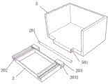
图3为本实用新型的底座和防水盖结构示意图。Fig. 3 is a structural schematic diagram of the base and the waterproof cover of the present invention.
图4为本实用新型的元件盒内部结构及底座连接结构示意图。Fig. 4 is a schematic diagram of the internal structure of the component box and the connection structure of the base of the utility model.
图5为本实用新型的元件盒与顶端固定盖连接结构示意图。Fig. 5 is a schematic diagram of the connection structure between the component box and the top fixing cover of the present invention.
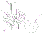
图6为本实用新型的空心柱与斜齿轮位置结构剖面示意图。Fig. 6 is a schematic cross-sectional view of the position structure of the hollow column and the helical gear of the present invention.
附图标记为:1、元件盒;101、滑轨;1011、凹槽;102、条形孔;103、空心柱;104、螺纹槽;2、底座;201、连接杆;202、滑槽;203、固定块;2031、固定孔;3、固定盖;301、螺纹孔;302、检修口;4、开关底板;5、防水盖;501、连接孔;6、螺纹杆;601、固定杆;7、固定螺栓;8、斜齿轮。Reference numerals are: 1, component box; 101, slide rail; 1011, groove; 102, strip hole; 103, hollow column; 104, thread groove; 2, base; 201, connecting rod; 202, chute; 203, fixed block; 2031, fixed hole; 3, fixed cover; 301, threaded hole; 302, inspection port; 4, switch bottom plate; 5, waterproof cover; 501, connecting hole; 6, threaded rod; 601, fixed rod; 7. Fixed bolt; 8. Helical gear.
具体实施方式Detailed ways
下面将结合本实用新型中的附图,对本实用新型中的技术方案进行清楚、完整地描述,另外,在以下的实施方式中记载的各结构的形态只不过是例示,本实用新型所涉及的一种配网继电保护整定器并不限定于在以下的实施方式中记载的各结构,在本领域普通技术人员在没有做出创造性劳动的前提下所获得的所有其他实施方式都属于本实用新型保护的范围。The technical scheme in the utility model will be clearly and completely described below in conjunction with the accompanying drawings in the utility model. In addition, the forms of each structure recorded in the following embodiments are only examples, and the aspects involved in the utility model A distribution network relay protection setter is not limited to the structures described in the following embodiments, and all other embodiments obtained by those of ordinary skill in the art without creative work belong to this practical The scope of the new type of protection.
参照图1-6所示,本实用新型提供了一种配网继电保护整定器,包括元件盒1;元件盒1的顶端固定连接有固定盖3,固定盖3的顶端固定连接有开关底板4,元件盒1底端两侧固定焊接有滑轨101,元件盒1底端滑轨101固定卡接有底座2,元件盒1前端两侧开设有条形孔102,条形孔102内固定连接有螺纹杆6Referring to Figures 1-6, the utility model provides a distribution network relay protection setter, including a
参照图2-图3所示,底座2顶端两侧开设有滑槽202,底座2后侧两端靠近滑槽202位置固定焊接有固定块203,固定块203两侧开设有固定孔2031,固定孔2031内固定卡接有连接杆201,固定块203通过连接杆201穿过两侧的固定孔2031固定连接有防水盖5,防水盖5前段为凸形,且凸出位置两侧开设有连接孔501,底座2顶端开设有检修口302检修口302内固定卡接有开关底板4。With reference to Fig. 2-shown in Fig. 3, there are
参照图2-图5所示,固定盖3顶端两侧开设有排列整齐的螺纹孔301,螺纹孔301内固定连接有固定螺栓7,固定螺栓7通过固定盖3两侧的螺纹孔301固定连接固定盖3底端的元件盒1。Referring to Figures 2-5, there are neatly arranged threaded
参照图2-图4所示,元件盒1包含底端两侧固定焊接的滑轨101,滑轨101两侧开设有凹槽1011,元件盒1底端靠近前段条形孔102位置均固定连接有空心柱103,空心柱103两侧设有孔槽且孔槽内均活动连接有斜齿轮8,斜齿轮8在靠近条形孔102一侧中心位置固定连接有螺纹杆6且螺纹杆6在远离斜齿轮8一端连接有固定螺母,斜齿轮8在远离条形孔102一侧中心固定连接有固定杆601且固定杆601另一端固定焊接在元件盒1开设条形孔102一侧的内壁,元件盒1内壁两侧设有排列整齐的螺纹槽104。Referring to Figures 2-4, the
参照图2-图5所示,固定螺栓7通过固定盖3顶端两侧开设的螺纹孔301连接元件盒1内壁两侧的螺纹槽104固定连接固定盖3和元件盒1,元件盒1底端两侧固定焊接的滑轨101通过滑轨101两侧开设的凹槽1011固定卡接在底座2两侧开设的滑槽202内。Referring to Figure 2-Figure 5, the
参照图3所示,底座2两侧开设的滑槽202与滑轨101两侧开设的凹槽1011尺寸相等,连接杆201穿过固定孔2031和连接孔501固定连接防水盖5和底座2,防水盖5通过连接杆201可前后翻转。Referring to Fig. 3, the
本实用新型的工作原理:Working principle of the utility model:
在安装使用时,首先将元件盒1和元件盒1顶端的固定盖3经固定螺栓7穿过固定盖3两侧的螺纹孔301,连接元件盒1内壁两侧与螺纹孔301对应的螺纹槽104固定连接,此时将需要安装的线路对准元件盒1底端的空心柱103底部,将线路推入后因空心柱103两侧设有斜齿轮8经过斜齿轮8的旋转使线路进入,并将推入的线路固定,因空心柱103一侧的斜齿轮8由固定杆601连接固定在元件盒1靠近条形孔102一侧内壁,另一侧的斜齿轮8通过螺纹杆6穿过条形孔102固定,使得安装完成的线路不会因晃动而脱落,安装完毕后若是需要拆除,只需将元件盒1前段两侧螺纹杆6上的螺母拧松,然后向向两侧推动即可将线路取出,安装调试完后,将元件盒1底端两侧设有的滑轨101对准底座2两侧开设的滑槽202,从下方将元件盒1缓缓向上推入,使得滑轨101两侧的凹槽1011卡接在滑槽202内,最后将卡接后的元件盒1连同底座2安装固定在所需位置,最后将底座2顶端通过连接杆201穿过固定块203两侧开设的固定孔2031连接防水盖5底端凸形上开设的连接孔501固定连接防水盖5,防水盖5通过连接杆201连接可前后翻转,在使用时若是发现异常,可以将固定盖3顶端开设的检修口302内固定卡接的开关底板4取出检查,检查后将开关底板4再次卡接,将防水盖5向下翻转遮盖元件盒1整体即安装完毕。When installing and using, first pass the
最后:以上所述仅为本实用新型的优选实施例而已,并不用于限制本实用新型,凡在本实用新型的精神和原则之内,所作的任何修改、等同替换、改进等,均应包含在本实用新型的保护范围之内。Finally: the above is only a preferred embodiment of the utility model, and is not intended to limit the utility model. Any modifications, equivalent replacements, improvements, etc. made within the spirit and principles of the utility model shall include Within the protection scope of the present utility model.
Claims (6)
Priority Applications (1)
| Application Number | Priority Date | Filing Date | Title |
|---|---|---|---|
| CN202223270252.5U CN219204080U (en) | 2022-12-07 | 2022-12-07 | Relay protection setter for distribution network |
Applications Claiming Priority (1)
| Application Number | Priority Date | Filing Date | Title |
|---|---|---|---|
| CN202223270252.5U CN219204080U (en) | 2022-12-07 | 2022-12-07 | Relay protection setter for distribution network |
Publications (1)
| Publication Number | Publication Date |
|---|---|
| CN219204080U true CN219204080U (en) | 2023-06-16 |
Family
ID=86712076
Family Applications (1)
| Application Number | Title | Priority Date | Filing Date |
|---|---|---|---|
| CN202223270252.5U Withdrawn - After Issue CN219204080U (en) | 2022-12-07 | 2022-12-07 | Relay protection setter for distribution network |
Country Status (1)
| Country | Link |
|---|---|
| CN (1) | CN219204080U (en) |
-
2022
- 2022-12-07 CN CN202223270252.5U patent/CN219204080U/en not_active Withdrawn - After Issue
Similar Documents
| Publication | Publication Date | Title |
|---|---|---|
| CN211306247U (en) | Relay protection debugging table | |
| CN104064969A (en) | Combined distribution box | |
| CN114744502A (en) | Combined electrical power distribution cabinet convenient to install and maintain | |
| CN216566020U (en) | Control cabinet of diesel generating set | |
| CN110176726B (en) | Mechanism for installing circuit breaker on switch cabinet | |
| CN208782317U (en) | A kind of emergency lighting distribution box facilitating installation | |
| CN208908300U (en) | A kind of Moveable distribution box | |
| CN209169724U (en) | An easy-to-remove distribution box | |
| CN216980465U (en) | Side-mounted vacuum circuit breaker with intelligent monitoring system | |
| CN224249200U (en) | Block terminal for assembled transformer substation | |
| CN212724590U (en) | Display screen module is with mounting structure convenient to butt joint | |
| CN211088870U (en) | A dual-power distribution box based on dual-power fault data monitoring | |
| CN209488108U (en) | A kind of electrical engineering distribution box being easily installed maintenance | |
| CN116864279A (en) | Novel mutual inductor box | |
| CN221126681U (en) | Block terminal of easy to assemble | |
| CN207926051U (en) | A kind of circuit breaker type ring main unit pressure relief device | |
| CN223259828U (en) | A switch cabinet status monitoring device | |
| CN223599316U (en) | A copper busbar fixing device for a power distribution cabinet | |
| CN221263012U (en) | A circuit breaker cabinet with internal dust cleaning structure | |
| CN220672992U (en) | Dual-power switching device easy to operate | |
| CN223218641U (en) | An electric energy metering box | |
| CN221961388U (en) | Combined distribution box with interlayer structure | |
| CN224110723U (en) | An outdoor electrical distribution box for building electrical systems | |
| CN221552499U (en) | Digital electric control device with bus control | |
| CN221806486U (en) | New energy anti-islanding protection device |
Legal Events
| Date | Code | Title | Description |
|---|---|---|---|
| GR01 | Patent grant | ||
| GR01 | Patent grant | ||
| AV01 | Patent right actively abandoned | ||
| AV01 | Patent right actively abandoned | ||
| AV01 | Patent right actively abandoned |
Granted publication date: 20230616 Effective date of abandoning: 20230830 |
|
| AV01 | Patent right actively abandoned |
Granted publication date: 20230616 Effective date of abandoning: 20230830 |