CN219199624U - Refrigerating and freezing device - Google Patents

Refrigerating and freezing device Download PDF

Info

Publication number
CN219199624U
CN219199624U CN202222648065.XU CN202222648065U CN219199624U CN 219199624 U CN219199624 U CN 219199624U CN 202222648065 U CN202222648065 U CN 202222648065U CN 219199624 U CN219199624 U CN 219199624U
Authority
CN
China
Prior art keywords
heat
section
heat storage
defrosting
refrigerating
Prior art date
Legal status (The legal status is an assumption and is not a legal conclusion. Google has not performed a legal analysis and makes no representation as to the accuracy of the status listed.)
Active
Application number
CN202222648065.XU
Other languages
Chinese (zh)
Inventor
延廷琪
赵发
毛宝龙
Current Assignee (The listed assignees may be inaccurate. Google has not performed a legal analysis and makes no representation or warranty as to the accuracy of the list.)
Qingdao Haier Refrigerator Co Ltd
Haier Smart Home Co Ltd
Original Assignee
Qingdao Haier Refrigerator Co Ltd
Haier Smart Home Co Ltd
Priority date (The priority date is an assumption and is not a legal conclusion. Google has not performed a legal analysis and makes no representation as to the accuracy of the date listed.)
Filing date
Publication date
Application filed by Qingdao Haier Refrigerator Co Ltd, Haier Smart Home Co Ltd filed Critical Qingdao Haier Refrigerator Co Ltd
Priority to CN202222648065.XU priority Critical patent/CN219199624U/en
Application granted granted Critical
Publication of CN219199624U publication Critical patent/CN219199624U/en
Active legal-status Critical Current
Anticipated expiration legal-status Critical

Links

Images

Classifications

    • Y—GENERAL TAGGING OF NEW TECHNOLOGICAL DEVELOPMENTS; GENERAL TAGGING OF CROSS-SECTIONAL TECHNOLOGIES SPANNING OVER SEVERAL SECTIONS OF THE IPC; TECHNICAL SUBJECTS COVERED BY FORMER USPC CROSS-REFERENCE ART COLLECTIONS [XRACs] AND DIGESTS
    • Y02—TECHNOLOGIES OR APPLICATIONS FOR MITIGATION OR ADAPTATION AGAINST CLIMATE CHANGE
    • Y02E—REDUCTION OF GREENHOUSE GAS [GHG] EMISSIONS, RELATED TO ENERGY GENERATION, TRANSMISSION OR DISTRIBUTION
    • Y02E60/00—Enabling technologies; Technologies with a potential or indirect contribution to GHG emissions mitigation
    • Y02E60/14—Thermal energy storage

Landscapes

  • Defrosting Systems (AREA)

Abstract

本实用新型涉及冷藏冷冻技术领域,特别是涉及一种冷藏冷冻装置。该冷藏冷冻装置包括:箱体,其内限定有蒸发器室和压机仓;蒸发器,设置在蒸发器室内;以及化霜装置,包括循环管路,其中,循环管路包括设置在压机仓内的蓄热段和设置在蒸发器室内的放热段,循环管路内容装有可在循环管路内流动的蓄热体,并且化霜装置配置成允许蓄热体在蓄热段内吸收压机仓内的热量,并允许蓄热体在放热段内放出热量以对蒸发器进行化霜。本实用新型的冷藏冷冻装置的化霜装置利用循环管路和可在循环管路内流动的蓄热体完成蓄热化霜循环,避免了由于额外设置其他传热介质导致的在热传递中的热量损耗,提高了对压机舱内热量的利用率,从而提高了化霜效率。
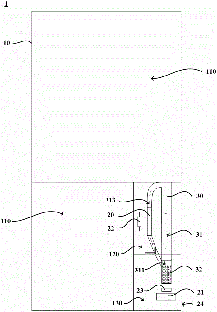
Figure 202222648065

The utility model relates to the technical field of refrigeration and freezing, in particular to a refrigeration and freezing device. The refrigerating and freezing device includes: a box body, which defines an evaporator chamber and a compressor chamber; an evaporator, which is arranged in the evaporator chamber; The heat storage section in the warehouse and the heat release section arranged in the evaporator chamber, the circulation pipeline is equipped with a heat storage body that can flow in the circulation pipeline, and the defrosting device is configured to allow the heat storage body to flow in the heat storage section Absorb the heat in the compressor chamber, and allow the heat storage body to release heat in the heat release section to defrost the evaporator. The defrosting device of the refrigerating and freezing device of the utility model utilizes the circulation pipeline and the heat accumulator that can flow in the circulation pipeline to complete the heat storage and defrosting cycle, which avoids the loss in heat transfer due to the additional setting of other heat transfer media. The heat loss improves the utilization rate of the heat in the compressor cabin, thereby improving the defrosting efficiency.

Figure 202222648065

Description

一种冷藏冷冻装置A refrigeration and freezing device

技术领域technical field

本实用新型涉及冷藏冷冻技术领域,特别是涉及一种冷藏冷冻装置。The utility model relates to the technical field of refrigeration and freezing, in particular to a refrigeration and freezing device.

背景技术Background technique

随着人们生活水平的不断提高和冰箱领域技术的不断发展,风冷无霜冰箱凭借着优秀的制冷效果和绝佳的无霜体验,逐步了成为用户在购入冰箱时的最佳选择。传统的风冷无霜冰箱通常以利用加热丝直接加热蒸发器的方式对蒸发器进行化霜,这种化霜方式会导致化霜时制冷间室的温升过大、化霜耗电较多。因此,现有的风冷无霜冰箱提出了利用冷凝器工作时产生的废热,并在化霜时将这些废热释放到蒸发器的表面的方式对蒸发器进行化霜。With the continuous improvement of people's living standards and the continuous development of refrigerator technology, air-cooled frost-free refrigerators have gradually become the best choice for users when purchasing refrigerators due to their excellent cooling effect and excellent frost-free experience. Traditional air-cooled frost-free refrigerators usually use heating wires to directly heat the evaporator to defrost the evaporator. This method of defrosting will cause the temperature rise of the refrigeration compartment to be too large during defrosting, and the defrosting will consume more power. . Therefore, the existing air-cooled frost-free refrigerator proposes to defrost the evaporator by using the waste heat generated during the operation of the condenser and releasing the waste heat to the surface of the evaporator during defrosting.

然而,现有的热管型蓄热除霜机构先利用相变蓄热材料蓄热,再利用两端分别与相变蓄热材料和蒸发器接触的重力热管来将相变蓄热材料所吸收的热量传递到蒸发器,管路设置复杂,生产成本较高,且在热量传递过程中对热量的损耗较大,导致了化霜效率较低的问题。However, the existing heat pipe type heat storage and defrosting mechanism first uses the phase change heat storage material to store heat, and then utilizes the gravity heat pipes with two ends in contact with the phase change heat storage material and the evaporator to transfer the heat absorbed by the phase change heat storage material. The heat is transferred to the evaporator, the pipeline arrangement is complicated, the production cost is high, and the heat loss is relatively large during the heat transfer process, which leads to the problem of low defrosting efficiency.

实用新型内容Utility model content

本实用新型的一个目的旨在克服现有技术的至少一个缺陷,提供一种化霜效率高的冷藏冷冻装置。One purpose of the present utility model is to overcome at least one defect of the prior art and provide a refrigeration and freezing device with high defrosting efficiency.

本实用新型的一个进一步的目的使热量充分传递到蒸发器的表面,以进一步提高化霜效率。A further object of the present invention is to fully transfer heat to the surface of the evaporator, so as to further improve the defrosting efficiency.

本实用新型的另一个进一步的目的是优化化霜装置的内部结构,提高化霜工作的稳定性。Another further purpose of the utility model is to optimize the internal structure of the defrosting device and improve the stability of the defrosting work.

为了实现上述目的,本实用新型提供一种冷藏冷冻装置,其包括:In order to achieve the above object, the utility model provides a refrigeration and freezing device, which includes:

箱体,其内限定有蒸发器室和压机舱;a tank defining an evaporator compartment and a compressor compartment therein;

蒸发器,设置在蒸发器室内;以及an evaporator disposed within the evaporator chamber; and

化霜装置,包括循环管路,其中,循环管路包括设置在压机舱内的蓄热段和设置在蒸发器室内的放热段,循环管路内容装有可在循环管路内流动的蓄热体,并且化霜装置配置成允许蓄热体在蓄热段内吸收压机舱内的热量,并允许蓄热体在放热段内放出热量以对蒸发器进行化霜。The defrosting device includes a circulation pipeline, wherein the circulation pipeline includes a heat storage section arranged in the compressor cabin and a heat release section arranged in the evaporator chamber, and the circulation pipeline is equipped with a heat storage section that can flow in the circulation pipeline. The thermal body, and the defrosting device is configured to allow the heat storage body to absorb the heat in the compressor cabin in the heat storage section, and allow the heat storage body to release heat in the heat release section to defrost the evaporator.

可选地,放热段套设在蒸发器上;并且Optionally, the exothermic section is sleeved on the evaporator; and

蓄热体包括多个蓄热颗粒,其中,蓄热颗粒的尺寸配置成可在放热段内流过蒸发器的大小。The heat storage body includes a plurality of heat storage particles, wherein the heat storage particles are sized to flow through the evaporator in the heat release section.

可选地,化霜装置还包括支撑件,其中,支撑件可移动地设置在循环管路内,并且支撑件配置成在冷藏冷冻装置正常制冷时位于蓄热段的底部以支撑蓄热体,并在冷藏冷冻装置启动化霜之后推动蓄热体从蓄热段流动到放热段。Optionally, the defrosting device further includes a support member, wherein the support member is movably arranged in the circulation pipeline, and the support member is configured to be located at the bottom of the heat storage section to support the heat storage body when the refrigerating and freezing device is normally cooled, And push the heat storage body to flow from the heat storage section to the heat release section after the refrigerating and freezing device starts to defrost.

可选地,循环管路在蓄热段处具有不完全封闭的底壁,支撑件在冷藏冷冻装置正常制冷时设置在底壁上;并且Optionally, the circulation pipeline has an incompletely closed bottom wall at the heat storage section, and the support member is arranged on the bottom wall when the refrigerating and freezing device is normally refrigerated; and

支撑件上开设有允许压机舱与蓄热段连通的开口。An opening is opened on the supporting member to allow the compressor cabin to communicate with the heat storage section.

可选地,循环管路还包括位于蓄热段和放热段之间的连接段,其中,连接段在蓄热体的循环方向上位于蓄热段的下游;并且Optionally, the circulation pipeline further includes a connection section between the heat storage section and the heat discharge section, wherein the connection section is located downstream of the heat storage section in the circulation direction of the heat storage body; and

支撑件可受控地在蓄热段和连接段内滑动。The support is controllably slidable within the heat storage section and the connecting section.

可选地,化霜装置还包括驱动组件,其中,驱动组件包括设置在循环管路的外侧的电机以及与电机传动连接的传动机构,传动机构和支撑件连接设置,并且驱动组件配置成在冷藏冷冻装置正常制冷时使支撑件位于蓄热段的底部,并在冷藏冷冻装置启动化霜之后启动电机以驱动传动机构带动支撑件沿着蓄热段和连接段从蓄热段的底部移动到放热段的入口,以将蓄热体送入放热段。Optionally, the defrosting device further includes a drive assembly, wherein the drive assembly includes a motor arranged on the outside of the circulation pipeline and a transmission mechanism connected to the motor, the transmission mechanism is connected to the support member, and the drive assembly is configured to When the refrigeration device is normally refrigerated, the support is located at the bottom of the heat storage section, and after the refrigerating and freezing device starts defrosting, the motor is started to drive the transmission mechanism to drive the support to move from the bottom of the heat storage section to the discharge area along the heat storage section and the connecting section. The entrance of the hot section to send the heat accumulator into the exothermic section.

可选地,化霜装置还包括设置在循环管路内的第一门,其中,第一门位于蓄热段和连接段之间;并且Optionally, the defrosting device further includes a first door arranged in the circulation pipeline, wherein the first door is located between the heat storage section and the connecting section; and

第一门配置成在冷藏冷冻装置正常制冷时处于关闭状态,并在冷藏冷冻装置启动化霜之后开启。The first door is configured to be closed when the refrigerating and freezing device is normally refrigerated, and to be opened after the refrigerating and freezing device starts defrosting.

可选地,化霜装置还包括设置在循环管路内的第二门,其中,第二门位于蒸发器的底部,并且第二门上开设有供化霜水流下的开口;Optionally, the defrosting device further includes a second door arranged in the circulation pipeline, wherein the second door is located at the bottom of the evaporator, and the second door is provided with an opening for the defrosting water to flow down;

冷藏冷冻装置的化霜过程包括按照时间顺序排序的化霜前期阶段和化霜后期阶段;并且The defrosting process of the refrigerating and freezing device includes a pre-defrosting stage and a post-defrosting stage sequenced in chronological order; and

第二门配置成在冷藏冷冻装置正常制冷时以及在化霜前期阶段处于关闭状态,并在化霜后期阶段开启。The second door is configured to be closed when the refrigerating and freezing device is normally refrigerated and in the early stage of defrosting, and to be opened in the late stage of defrosting.

可选地,冷藏冷冻装置还包括:Optionally, the refrigerated freezer also includes:

接水盘,设置在蒸发器室内循环管路之外的位置处,用于接收化霜水;并且a water receiving tray, arranged at a position outside the circulation pipeline in the evaporator chamber, for receiving defrosting water; and

循环管路在放热段的底部开设有允许化霜水流入接水盘的开口。The circulation pipeline is provided with an opening at the bottom of the heat release section to allow the defrosting water to flow into the water receiving tray.

可选地,循环管路还包括位于蓄热段和放热段之间的回流段,其中,回流段在蓄热体的循环方向上位于放热段的下游;并且Optionally, the circulation pipeline further includes a return section located between the heat storage section and the heat release section, wherein the return section is located downstream of the heat release section in the circulation direction of the heat storage body; and

化霜装置包括设置在循环管路内的第三门,第三门位于放热段和回流段之间,并且第三门配置成在冷藏冷冻装置正常制冷时以及在冷藏冷冻装置的化霜过程中处于关闭状态,并在冷藏冷冻装置结束化霜之后开启。The defrosting device includes a third door arranged in the circulation pipeline, the third door is located between the heat release section and the return section, and the third door is configured to The center is closed and opened after the refrigerated freezer finishes defrosting.

本实用新型的冷藏冷冻装置的化霜装置包括循环管路和可在循环管路内流动的蓄热体,其中,循环管路包括设置在压机舱内的蓄热段和设置在蒸发器室内的放热段,并且使得蓄热体在蓄热段内吸收压机舱内的热量、在放热段内放出热量以对蒸发器进行化霜,构成了蓄热化霜循环。本实用新型的冷藏冷冻装置利用蓄热化霜循环,实现了充分利用压机舱内的废热,无需额外设置专用于加热化霜水的加热器,有效地降低了化霜造成的能源损耗,降低了化霜能耗。并且本实用新型的冷藏冷冻装置使蓄热体直接参与到吸热和放热工作流程中,不需要其他传热介质的二次热传递,减少了热传递中的热量损耗,提高了对压机舱内热量的利用率,从而提高了化霜效率。The defrosting device of the refrigerating and freezing device of the present invention includes a circulation pipeline and a heat storage body that can flow in the circulation pipeline, wherein the circulation pipeline includes a heat storage section arranged in the compressor cabin and a heat storage body arranged in the evaporator chamber. heat release section, and make the heat storage body absorb the heat in the compressor cabin in the heat storage section and release heat in the heat release section to defrost the evaporator, forming a heat storage defrost cycle. The refrigerating and freezing device of the utility model utilizes the heat storage and defrosting cycle to fully utilize the waste heat in the press cabin, and does not need additional heaters for heating the defrosting water, which effectively reduces the energy loss caused by defrosting and reduces the Defrost energy consumption. Moreover, the refrigerating and freezing device of the utility model makes the heat storage body directly participate in the heat absorption and heat release work flow, does not require secondary heat transfer of other heat transfer media, reduces heat loss in heat transfer, and improves the efficiency of the compressor cabin. The utilization rate of internal heat improves the defrosting efficiency.

进一步地,本实用新型的冷藏冷冻装置将放热段套设在蒸发器上,实现了蓄热体和蒸发器的表面之间的充分接触,使得蓄热体散出的热量充分传递到蒸发器的表面,进一步提高了化霜效率。另外,本实用新型的冷藏冷冻装置的蓄热体包括多个蓄热颗粒,并且蓄热颗粒的尺寸配置成可在放热段内流过蒸发器的大小,在保证了蓄热体的流动性的同时,避免了蓄热体和蒸发器表面霜层融化后形成的化霜水混杂在一起,从而便于蓄热体的循环利用。Further, the refrigerating and freezing device of the present invention sets the heat release section on the evaporator, which realizes sufficient contact between the heat storage body and the surface of the evaporator, so that the heat emitted by the heat storage body is fully transferred to the evaporator The surface further improves the defrosting efficiency. In addition, the thermal storage body of the refrigeration and freezing device of the present invention includes a plurality of thermal storage particles, and the size of the thermal storage particles is configured to flow through the evaporator in the heat release section, ensuring the fluidity of the thermal storage body At the same time, it avoids the mixing of the heat storage body and the defrost water formed after the frost layer on the surface of the evaporator melts, thereby facilitating the recycling of the heat storage body.

更进一步地,本实用新型的冷藏冷冻装置的化霜装置还包括支撑件,其中,支撑件可移动地设置在循环管路内,并且支撑件配置成在冷藏冷冻装置正常制冷时位于蓄热段的底部以支撑蓄热体,并在冷藏冷冻装置启动化霜之后推动蓄热体从蓄热段流动到放热段,为蓄热体在部分流动路径上的流动提供动力,实现了蓄热体的循环利用,提高了化霜工作的稳定性。Furthermore, the defrosting device of the refrigerating and freezing device of the present invention also includes a support member, wherein the support member is movably arranged in the circulation pipeline, and the support member is configured to be located in the heat storage section when the refrigerating and freezing device is normally refrigerated. to support the heat storage body at the bottom, and push the heat storage body to flow from the heat storage section to the heat release section after the refrigerating and freezing device starts defrosting, providing power for the flow of the heat storage body on part of the flow path, and realizing the heat storage body The recycling utilization improves the stability of defrosting work.

根据下文结合附图对本实用新型具体实施例的详细描述,本领域技术人员将会更加明了本实用新型的上述以及其他目的、优点和特征。According to the following detailed description of specific embodiments of the utility model in conjunction with the accompanying drawings, those skilled in the art will be more aware of the above and other objectives, advantages and features of the utility model.

附图说明Description of drawings

后文将参照附图以示例性而非限制性的方式详细描述本实用新型的一些具体实施例。附图中相同的附图标记标示了相同或类似的部件或部分。本领域技术人员应该理解,这些附图未必是按比例绘制的。附图中:Hereinafter, some specific embodiments of the present utility model will be described in detail in an exemplary rather than restrictive manner with reference to the accompanying drawings. The same reference numerals in the drawings designate the same or similar parts or parts. Those skilled in the art will appreciate that the drawings are not necessarily drawn to scale. In the attached picture:

图1是根据本实用新型一个实施例的冷藏冷冻装置的结构示意图;Fig. 1 is a schematic structural view of a refrigerating and freezing device according to an embodiment of the present invention;

图2是根据本实用新型一个实施例的冷藏冷冻装置的部分结构示意图;Fig. 2 is a partial structural schematic diagram of a refrigeration and freezing device according to an embodiment of the present invention;

图3是根据本实用新型另一个实施例的冷藏冷冻装置的部分结构示意图;Fig. 3 is a partial structural schematic diagram of a refrigerating and freezing device according to another embodiment of the present invention;

图4是根据本实用新型一个实施例的冷藏冷冻装置的化霜装置的部分结构示意图。Fig. 4 is a partial structural schematic diagram of a defrosting device of a refrigerating and freezing device according to an embodiment of the present invention.

具体实施方式Detailed ways

下面将参照附图更详细地描述本实用新型的示例性实施例。虽然附图中显示了本实用新型的示例性实施例,然而应当理解,可以以各种形式实现本实用新型而不应被这里阐述的实施例所限制。相反,提供这些实施例是为了能够更透彻地理解本公开,并且能够将本实用新型的范围完整的传达给本领域的技术人员。Exemplary embodiments of the present invention will be described in more detail below with reference to the accompanying drawings. Although exemplary embodiments of the invention are shown in the drawings, it should be understood that the invention may be embodied in various forms and should not be limited to the embodiments set forth herein. Rather, these embodiments are provided so that the present disclosure can be more thoroughly understood, and the scope of the present invention can be fully conveyed to those skilled in the art.

本实用新型提供了一种冷藏冷冻装置,图1是根据本实用新型一个实施例的冷藏冷冻装置的结构示意图。参见图1,本实用新型的冷藏冷冻装置1包括箱体10、蒸发器20和化霜装置30。The utility model provides a refrigerating and freezing device, and Fig. 1 is a structural schematic diagram of the refrigerating and freezing device according to an embodiment of the utility model. Referring to FIG. 1 , the refrigerating and freezing device 1 of the present invention includes a box body 10 , an evaporator 20 and a defrosting device 30 .

箱体10其内限定有用于储存物品的储物空间110、蒸发器室120和压机舱130。图1所示实施例的冷藏冷冻装置1的箱体10内限定有两个储物空间110,在未示出的实施例中,冷藏冷冻装置1的箱体10内也可以仅限定有一个储物空间110或限定有多于两个的储物空间110。The box body 10 defines a storage space 110 for storing articles, an evaporator room 120 and a compressor room 130 therein. Two storage spaces 110 are defined in the case body 10 of the refrigerating-freezing device 1 of the embodiment shown in FIG. storage space 110 or more than two storage spaces 110 are defined.

冷藏冷冻装置1制冷系统包括蒸发器20、压缩机(图中未示出)和冷凝器21。蒸发器20设置于蒸发器室120内,用于为储物空间110提供冷量。蒸发器室120设置在储物空间110的后方。压机舱130设置在蒸发器室120的下方。压缩机和冷凝器21均可以设置在压机舱130内。可以理解的是,制冷系统除了蒸发器20、压缩机和冷凝器21,还可以包括节流元件(图中未示出)等结构。压缩机、冷凝器21、节流元件和蒸发器20可通过制冷剂管路连接形成制冷循环回路。在冷藏冷冻装置1正常制冷时,压缩机和冷凝器21运行并产生的热量散发到压机舱130中,蒸发器20对流经其的空气进行冷却,从而形成用于供向储物空间110的冷却气流。在蒸发器室120内还设置有制冷风机22,用于促使流经蒸发器20的冷却气流吹向储物空间110。The refrigerating system of the refrigerating and freezing device 1 includes an evaporator 20 , a compressor (not shown in the figure) and a condenser 21 . The evaporator 20 is disposed in the evaporator chamber 120 for providing cold energy to the storage space 110 . The evaporator compartment 120 is disposed behind the storage space 110 . The compressor room 130 is disposed below the evaporator room 120 . Both the compressor and the condenser 21 may be disposed in the compressor compartment 130 . It can be understood that, in addition to the evaporator 20, the compressor and the condenser 21, the refrigerating system may also include throttling elements (not shown in the figure) and other structures. The compressor, the condenser 21, the throttling element and the evaporator 20 can be connected through refrigerant pipelines to form a refrigeration cycle. When the refrigerating and freezing device 1 is normally refrigerated, the compressor and the condenser 21 operate and the heat generated is dissipated into the compressor compartment 130, and the evaporator 20 cools the air flowing through it, thereby forming a cooling system for supplying to the storage space 110. airflow. A cooling fan 22 is also provided in the evaporator chamber 120 for driving the cooling air flowing through the evaporator 20 to the storage space 110 .

化霜装置30包括循环管路31。循环管路31内容装有可在循环管路31内流动的蓄热体32。循环管路31内部中空形成有供蓄热体32循环流动的流通通道。循环管路31包括设置在压机舱130内的蓄热段311和设置在蒸发器室120内的放热段313,并且化霜装置30配置成允许蓄热体32在蓄热段311内吸收压机舱130内的热量,并允许蓄热体32在放热段313内放出热量以对蒸发器20进行化霜。The defrosting device 30 includes a circulation pipeline 31 . The heat accumulator 32 that can flow in the circulation line 31 is installed in the circulation line 31 . The inside of the circulation pipeline 31 is hollow to form a circulation passage for the heat storage body 32 to circulate. The circulation pipeline 31 includes a heat storage section 311 arranged in the compressor room 130 and a heat release section 313 arranged in the evaporator chamber 120 , and the defrosting device 30 is configured to allow the heat storage body 32 to absorb pressure in the heat storage section 311 heat in the nacelle 130 , and allow the heat storage body 32 to release heat in the heat release section 313 to defrost the evaporator 20 .

具体地,压机舱130内还设置有散热风机23。在冷藏冷冻装置1正常制冷时,散热风机23运转,以将压机舱130中的热量吹向蓄热段311中的蓄热体32。蓄热段311位于散热风机23的下游,以使蓄热体32充分吸收压机舱130中的热量。另外,放热段313至少部分地与蒸发器20贴紧设置。在冷藏冷冻装置1启动化霜之后,当蓄热体32流动到放热段313时,需要低温的蒸发器20表面,释放出蓄积的热量,以对蒸发器20进行加热。Specifically, a cooling fan 23 is also provided in the compressor cabin 130 . When the refrigerating and freezing device 1 is cooling normally, the cooling fan 23 operates to blow the heat in the compressor compartment 130 to the heat storage body 32 in the heat storage section 311 . The heat storage section 311 is located downstream of the cooling fan 23 so that the heat storage body 32 can fully absorb the heat in the compressor cabin 130 . In addition, the heat dissipation section 313 is at least partially disposed close to the evaporator 20 . After the refrigerating and freezing device 1 starts defrosting, when the thermal accumulator 32 flows to the heat release section 313 , a low-temperature surface of the evaporator 20 is needed to release the accumulated heat to heat the evaporator 20 .

本实施例的冷藏冷冻装置1的化霜装置30包括循环管路31和可在循环管路31内流动的蓄热体32,其中,循环管路31包括设置在压机舱130内的蓄热段311和设置在蒸发器室120内的放热段313,并且使得蓄热体32在蓄热段311内吸收压机舱130内的热量、在放热段313内放出热量以对蒸发器20进行化霜,构成了蓄热化霜循环。本实用新型的冷藏冷冻装置1利用蓄热化霜循环,实现了充分利用压机舱130内的废热,无需额外设置专用于加热化霜水的加热器,有效地降低了化霜造成的能源损耗,降低了化霜能耗。并且本实用新型的冷藏冷冻装置1使蓄热体32直接参与到吸热和放热工作流程中,不需要其他传热介质的二次热传递,减少了热传递中的热量损耗,提高了对压机舱130内热量的利用率,从而提高了化霜效率。The defrosting device 30 of the refrigerating and freezing device 1 of this embodiment includes a circulation pipeline 31 and a heat storage body 32 that can flow in the circulation pipeline 31, wherein the circulation pipeline 31 includes a heat storage section arranged in the compressor cabin 130 311 and the heat release section 313 arranged in the evaporator chamber 120, and make the heat accumulator 32 absorb the heat in the compressor cabin 130 in the heat storage section 311 and release the heat in the heat release section 313 to evaporator 20 Frost constitutes a thermal storage defrost cycle. The refrigerating and freezing device 1 of the present utility model utilizes the heat storage and defrosting cycle to fully utilize the waste heat in the compressor cabin 130, and does not need additional heaters dedicated to heating the defrosting water, which effectively reduces the energy loss caused by defrosting. Reduced defrosting energy consumption. Moreover, the refrigerating and freezing device 1 of the present utility model makes the heat storage body 32 directly participate in the heat absorption and heat release work flow, does not require secondary heat transfer of other heat transfer media, reduces heat loss in heat transfer, and improves the efficiency of the heat transfer process. The utilization rate of the heat in the compressor cabin 130 improves the defrosting efficiency.

在一些实施例中,如图1所示,压机舱130内的热量可以由冷凝器21在正常工作时散发产生。在该实施例中,散热风机23设置在冷凝器21的上方,并且蓄热段311位于散热风机23的上方,提高了对冷凝器21热量的利用率,提高对化霜水进行加热的加热效率,从而保证了化霜效率。In some embodiments, as shown in FIG. 1 , the heat in the compressor compartment 130 can be generated by dissipating heat from the condenser 21 during normal operation. In this embodiment, the cooling fan 23 is arranged above the condenser 21, and the heat storage section 311 is located above the cooling fan 23, which improves the utilization rate of the heat of the condenser 21 and improves the heating efficiency of heating the defrosting water , so as to ensure the defrosting efficiency.

在一些实施例中,如图1所示,压机舱130内还设置有可受控地开启或关闭的散热口24。冷藏冷冻装置1还包括用于检测蓄热体32的温度以及冷凝器21的温度的温度传感器(图中未示出)。散热口24配置为在正常制冷时关闭,并在蓄热体32和冷凝器21之间的温度差达到预设温差阈值时开启,已散出多余热量。预设温差阈值可以根据预先实验确定。在一个具体实施例中,预设温差阈值的范围为1~10℃。在蓄热体32和冷凝器21之间的温度差小于预设温差阈值时,蓄热体32的温度既能够满足化霜要求,又可避免由于温度过高使得在对蒸发器20化霜时蒸发器室120内的空气升温过多对储物空间110带来的不良影响。例如,预设温差阈值可以为3℃,以确保使用足够热的蓄热体32参与到化霜过程中,保证了化霜的效率。In some embodiments, as shown in FIG. 1 , a heat dissipation vent 24 that can be opened or closed in a controlled manner is also provided in the compressor cabin 130 . The refrigerator-freezer 1 further includes a temperature sensor (not shown) for detecting the temperature of the heat storage body 32 and the temperature of the condenser 21 . The heat dissipation port 24 is configured to be closed during normal cooling, and opened when the temperature difference between the heat storage body 32 and the condenser 21 reaches a preset temperature difference threshold to dissipate excess heat. The preset temperature difference threshold can be determined according to experiments in advance. In a specific embodiment, the range of the preset temperature difference threshold is 1-10°C. When the temperature difference between the heat storage body 32 and the condenser 21 is less than the preset temperature difference threshold, the temperature of the heat storage body 32 can not only meet the defrosting requirements, but also avoid defrosting the evaporator 20 due to the high temperature. Excessive temperature rise of the air in the evaporator chamber 120 has adverse effects on the storage space 110 . For example, the preset temperature difference threshold may be 3° C. to ensure that the heat storage body 32 with sufficient heat is used to participate in the defrosting process, thereby ensuring the defrosting efficiency.

图2是根据本实用新型一个实施例的冷藏冷冻装置的部分结构示意图。在该实施例中,如图2所示,循环管路31还包括位于蓄热段311和放热段313之间的连接段312和回流段314。Fig. 2 is a partial structural schematic diagram of a refrigerating and freezing device according to an embodiment of the present invention. In this embodiment, as shown in FIG. 2 , the circulation pipeline 31 further includes a connection section 312 and a return section 314 located between the heat storage section 311 and the heat release section 313 .

连接段312在蓄热体32的循环方向上位于蓄热段311的下游,回流段314在蓄热体32的循环方向上位于放热段313的下游。由此,构建出由蓄热段311、连接段312、放热段313和回流段314依次连通而成的循环管路31。也就是说,蓄热体32在循环管路31内的流动路径为依次流经蓄热段311、连接段312、放热段313和回流段314,再回到蓄热段311,从而构成一次完整的循环流动。需要说明的是,蓄热段311、连接段312、放热段313和回流段314是为了便于说明循环管路31的布置位置和蓄热体32的循环流动过程将循环管路31在空间上的划分开来的几个区段,不是特指四个相互独立的组装部分,本实用新型对循环管路31的具体结构和具体组装方式不作限定。The connection section 312 is located downstream of the heat storage section 311 in the circulation direction of the heat storage body 32 , and the return section 314 is located downstream of the heat release section 313 in the circulation direction of the heat storage body 32 . Thus, a circulation pipeline 31 formed by connecting the heat storage section 311 , the connection section 312 , the heat release section 313 and the return section 314 sequentially is constructed. That is to say, the flow path of the heat storage body 32 in the circulation pipeline 31 is to flow through the heat storage section 311, the connection section 312, the heat release section 313 and the return section 314 in sequence, and then return to the heat storage section 311, thereby forming a Complete circular flow. It should be noted that the heat storage section 311, the connection section 312, the heat dissipation section 313 and the return section 314 are for the convenience of explaining the arrangement position of the circulation pipeline 31 and the circulation flow process of the heat storage body 32 to make the circulation pipeline 31 spatially The divided sections do not specifically refer to four mutually independent assembly parts, and the utility model does not limit the specific structure and specific assembly method of the circulation pipeline 31 .

图3是根据本实用新型另一个实施例的冷藏冷冻装置的部分结构示意图。在该实施例中,化霜装置30还包括设置在循环管路31内的可受控地开启或关闭蓄热段311和放热段313之间的连通关系的开闭装置(图中未示出)。开闭装置配置成在冷藏冷冻装置1正常制冷时处于关闭状态,并在冷藏冷冻装置1启动化霜之后至少部分的开启以允许蓄热体32从蓄热段311流到放热段313。Fig. 3 is a partial structural schematic diagram of a refrigerating and freezing device according to another embodiment of the present invention. In this embodiment, the defrosting device 30 also includes an opening and closing device (not shown in the figure) that is provided in the circulation line 31 and can controllably open or close the communication relationship between the heat storage section 311 and the heat release section 313 out). The opening and closing device is configured to be closed when the refrigerating and freezing device 1 is normally cooling, and to be at least partially opened after the refrigerating and freezing device 1 starts defrosting to allow the heat storage body 32 to flow from the heat storage section 311 to the heat release section 313 .

在一些实施例中,开闭装置包括第一门33。也就是说,所述化霜装置30还包括设置在循环管路31内的第一门33。具体地,如图2所示,第一门33位于蓄热段311和连接段312之间。第一门33配置成在冷藏冷冻装置1正常制冷时处于关闭状态,关闭状态如图2所示,并在冷藏冷冻装置1启动化霜之后开启,开启状态如图3所示。In some embodiments, the opening and closing device includes a first door 33 . That is to say, the defrosting device 30 also includes a first door 33 disposed in the circulation pipeline 31 . Specifically, as shown in FIG. 2 , the first door 33 is located between the heat storage section 311 and the connection section 312 . The first door 33 is configured to be in a closed state when the refrigerating and freezing device 1 is normally cooling, as shown in FIG.

进一步地,如图2和图3所示,开闭装置还包括第三门35。也就是说,化霜装置30包括设置在循环管路31内的第三门35,第三门35位于放热段313和回流段314之间。第三门35配置成在冷藏冷冻装置1正常制冷时以及在冷藏冷冻装置1的化霜过程中处于关闭状态,关闭状态如图2所示,并在冷藏冷冻装置1结束化霜之后开启。Further, as shown in FIGS. 2 and 3 , the opening and closing device further includes a third door 35 . That is to say, the defrosting device 30 includes a third door 35 disposed in the circulation pipeline 31 , and the third door 35 is located between the heat release section 313 and the return section 314 . The third door 35 is configured to be closed when the refrigerating-freezing device 1 is normally cooling and during the defrosting process of the refrigerating-freezing device 1 , as shown in FIG. 2 , and opened after the refrigerating-freezing device 1 finishes defrosting.

本实施例的冷藏冷冻装置1通过设置有第一门33和第三门35,实现了在冷藏冷冻装置1正常制冷时关闭蓄热段311和放热段313之间的连通关系,避免了压机舱130内的热量通过循环管路31直接流道蒸发器20,同时也避免了蒸发器20的冷量通过循环管路31泄露,保证了蒸发器20的制冷效率。The refrigerating and freezing device 1 of this embodiment is provided with the first door 33 and the third door 35, which realizes closing the communication relationship between the heat storage section 311 and the heat releasing section 313 when the refrigerating and freezing device 1 is normally refrigerated, avoiding pressure. The heat in the nacelle 130 directly flows through the evaporator 20 through the circulation pipeline 31 , and at the same time, the cooling capacity of the evaporator 20 is prevented from leaking through the circulation pipeline 31 , thereby ensuring the refrigeration efficiency of the evaporator 20 .

在一些实施例中,如图2和图3所示,放热段313套设在蒸发器20上。具体地,蒸发器20为翅片式蒸发器。也就是说,在蓄热体32流动到放热段313时,可以从蒸发器20的翅片中流过,以与蒸发器20的表面充分接触。In some embodiments, as shown in FIG. 2 and FIG. 3 , the heat release section 313 is sleeved on the evaporator 20 . Specifically, the evaporator 20 is a finned evaporator. That is to say, when the heat accumulator 32 flows to the heat releasing section 313 , it may flow through the fins of the evaporator 20 to fully contact with the surface of the evaporator 20 .

进一步地,蓄热体32包括多个蓄热颗粒。具体地,蓄热颗粒可采用刚玉莫来石制成,其主要构成成分是氧化铝、高岭土和少量添加剂,制作工艺为一般陶瓷工艺,在1350℃左右烧制而成。采用刚玉莫来石制成的蓄热颗粒具有重烧线收缩率低、高温荷重软化温度高、耐腐蚀、强度高、蓄放热量大、热震稳定性好、导热性能好、热膨胀系数小等显著特点。另外,蓄热颗粒的尺寸配置成可在放热段313内流过蒸发器20的大小。对于采用翅片式蒸发器的冷藏冷冻装置1,蓄热颗粒的最大粒径小于蒸发器20各个翅片之间形成的缝隙。具体地,蓄热颗粒包括陶瓷小球、碎石等。在一个具体实施例中,如图2和图3所示,选用直径相同且直径小于5mm的陶瓷小球构成蓄热体32,提高了蓄热体32流动的顺畅性,从而允许蓄热体32更均匀地分布在蒸发器20内,从而均匀地对蒸发器20的各处进行加热化霜,缩短了化霜时间,提高了化霜效果。Further, the heat storage body 32 includes a plurality of heat storage particles. Specifically, the heat storage particles can be made of corundum mullite, the main components of which are alumina, kaolin and a small amount of additives, and the production process is a general ceramic process, which is fired at about 1350°C. The heat storage particles made of corundum mullite have low linear shrinkage after re-burning, high softening temperature under high temperature load, corrosion resistance, high strength, large heat storage and discharge, good thermal shock stability, good thermal conductivity, small thermal expansion coefficient, etc. Notable features. In addition, the heat storage particles are sized to flow through the evaporator 20 in the heat release section 313 . For the refrigerating and freezing device 1 using a finned evaporator, the maximum particle size of the heat storage particles is smaller than the gap formed between the fins of the evaporator 20 . Specifically, the heat storage particles include ceramic pellets, crushed stones and the like. In a specific embodiment, as shown in Fig. 2 and Fig. 3, ceramic balls with the same diameter and less than 5 mm in diameter are used to form the regenerator 32, which improves the smoothness of the flow of the regenerator 32, thereby allowing the regenerator 32 More evenly distributed in the evaporator 20, so as to uniformly heat and defrost all parts of the evaporator 20, shorten the defrosting time, and improve the defrosting effect.

在该实施例中,放热段313的长度大于蒸发器20在纵向方向上的尺寸,以使蓄热体32在放热段313内具有位于蒸发器20上方、蒸发器20的翅片之间、蒸发器20下方这多个位置。另外,放热段313可以在紧邻蒸发器20的翅片的位置处开设有允许气流流经蒸发器20的翅片之间的间隙的开口,以避免影响蒸发器20在正常制冷时的制冷效率。放热段313上开设的开口的最大口径小于蓄热颗粒的最小粒径,也就是说,放热段313上开设的开口只允许空气或化霜水流出,不允许蓄热颗粒流出,以便蓄热体32的循环利用。In this embodiment, the length of the heat release section 313 is greater than the dimension of the evaporator 20 in the longitudinal direction, so that the heat storage body 32 has a position above the evaporator 20 and between the fins of the evaporator 20 in the heat release section 313 . , These multiple positions below the evaporator 20. In addition, the heat release section 313 can be provided with an opening at a position adjacent to the fins of the evaporator 20 to allow the airflow to flow through the gap between the fins of the evaporator 20, so as to avoid affecting the cooling efficiency of the evaporator 20 during normal cooling. . The maximum diameter of the opening on the heat release section 313 is smaller than the minimum particle diameter of the heat storage particles, that is to say, the opening on the heat release section 313 only allows air or defrosting water to flow out, and does not allow the heat storage particles to flow out, so as to store Recycling of the thermal body 32 .

本实施例的冷藏冷冻装置1将放热段313套设在蒸发器20上,实现了蓄热体32和蒸发器20的表面之间的充分接触,使得蓄热体32散出的热量充分传递到蒸发器20的表面,进一步提高了化霜效率。另外,本实用新型的冷藏冷冻装置1的蓄热体32包括多个蓄热颗粒,并且蓄热颗粒的尺寸配置成可在放热段313内流过蒸发器20的大小,在保证了蓄热体32的流动性的同时,避免了蓄热体32和蒸发器20表面霜层融化后形成的化霜水混杂在一起,从而实现了蓄热体32的循环利用。In the refrigerating and freezing device 1 of this embodiment, the heat release section 313 is sleeved on the evaporator 20 to realize sufficient contact between the heat storage body 32 and the surface of the evaporator 20, so that the heat dissipated by the heat storage body 32 is fully transferred. to the surface of the evaporator 20, further improving the defrosting efficiency. In addition, the heat accumulator 32 of the refrigerating and freezing device 1 of the present utility model includes a plurality of heat accumulating particles, and the size of the heat accumulating particles is configured to be able to flow through the evaporator 20 in the heat release section 313. While improving the fluidity of the heat storage body 32, it is avoided that the heat storage body 32 and the defrost water formed after the frost layer on the surface of the evaporator 20 melts are mixed together, thereby realizing the recycling of the heat storage body 32.

在一些实施例中,冷藏冷冻装置1的化霜过程包括按照时间顺序排序的化霜前期阶段和化霜后期阶段。在蒸发器20满足常规的化霜结束条件时,确定冷藏冷冻装置1结束化霜前期阶段,进入化霜后期阶段。并且化霜后期阶段的工作时长可根据需求确定,在一些具体的实施例中,化霜后期阶段的工作时长的范围为1~10min。例如,化霜后期阶段的工作时长为3min。In some embodiments, the defrosting process of the refrigerating and freezing device 1 includes a pre-defrosting stage and a post-defrosting stage sequenced in chronological order. When the evaporator 20 meets the conventional defrosting end conditions, it is determined that the refrigerating and freezing device 1 ends the early defrosting stage and enters the late defrosting stage. In addition, the working time of the late defrosting stage can be determined according to requirements. In some specific embodiments, the working time of the late defrosting stage ranges from 1 to 10 minutes. For example, the working time of the late stage of defrosting is 3 minutes.

在此基础上,化霜装置30还包括设置在循环管路31内的第二门34。具体地,如图2和图3所示,第二门34位于蒸发器20的底部。第二门34配置成在冷藏冷冻装置1正常制冷时以及在化霜前期阶段处于关闭状态,并在化霜后期阶段开启。另外,设置在放热段313的底部的第三门35配置成在冷藏冷冻装置1的化霜过程中处于关闭状态。也就是说,在化霜前期阶段第二门34处于关闭状态,使得蓄热体32可停留在蒸发器20处直接对蒸发器20进行加热。在蒸发器20满足常规的化霜结束条件以进入化霜后期阶段时,第二门34开启,允许蓄热体32流过蒸发器20,并停留在蒸发器20和第三门35之间,使得蓄热体32的上半部分继续放热,对蒸发器20表面残存的化霜水进行加热并使其蒸发,避免了蒸发器20在进行后续制冷工作时表面残存的化霜水再次结霜或结冰,保证了蒸发器20的后续制冷工作的制冷效率。On this basis, the defrosting device 30 further includes a second door 34 disposed in the circulation pipeline 31 . Specifically, as shown in FIGS. 2 and 3 , the second door 34 is located at the bottom of the evaporator 20 . The second door 34 is configured to be closed when the refrigerating-freezer 1 is normally cooling and in the early defrosting stage, and opened in the late defrosting stage. In addition, the third door 35 disposed at the bottom of the heat releasing section 313 is configured to be closed during the defrosting process of the refrigerating and freezing device 1 . That is to say, in the early defrosting stage, the second door 34 is in a closed state, so that the heat storage body 32 can stay at the evaporator 20 to directly heat the evaporator 20 . When the evaporator 20 meets the conventional defrosting end conditions to enter the late stage of defrosting, the second door 34 is opened to allow the heat storage body 32 to flow through the evaporator 20 and stay between the evaporator 20 and the third door 35, Make the upper half of the heat storage body 32 continue to release heat, heat and evaporate the defrosted water remaining on the surface of the evaporator 20, and prevent the defrosted water remaining on the surface of the evaporator 20 from frosting again when the evaporator 20 performs subsequent cooling work or freeze, ensuring the cooling efficiency of the evaporator 20 for subsequent cooling work.

进一步地,第二门34上开设有供化霜水流下的开口。在一个具体实施例中,第二门34可以为网状结构。具体地,第二门34上开设的开口的最大口径小于蓄热颗粒的最小粒径,也就是说,第二门34上开设的开口只允许化霜水流出,不允许蓄热颗粒流出,实现了在化霜的过程中可以排出化霜水的同时,继续保证蓄热体32停留在蒸发器20处对其进行加热化霜,提高了化霜效率。Further, the second door 34 is provided with an opening for the defrosting water to flow down. In a specific embodiment, the second door 34 may be a mesh structure. Specifically, the maximum diameter of the opening on the second door 34 is smaller than the minimum particle diameter of the heat storage particles, that is to say, the opening on the second door 34 only allows the defrosting water to flow out, and does not allow the heat storage particles to flow out. In order to discharge the defrosting water during the defrosting process, the thermal storage body 32 is kept at the evaporator 20 to heat and defrost it, thereby improving the defrosting efficiency.

另外,本实施例的冷藏冷冻装置1还包括接水盘36。接水盘36设置在蒸发器室120内循环管路31之外的位置处,用于接收化霜水。具体地,如图2所示,接水盘36设置在蒸发器20的下方,且邻近第三门35的位置处。并且循环管路31在放热段313的底部开设有允许化霜水流入接水盘的开口37,实现了在冷藏冷冻装置1的化霜过程中产生的化霜水流经放热段313后均流入接水盘,保证了化霜水不会经由回流段314流入压机舱130,保证了散热风机23的工作稳定性。开口37的最大口径小于蓄热颗粒的最小粒径,也就是说,开口37只允许化霜水流入到接水盘,不允许蓄热颗粒流出,以便蓄热体32的循环利用。In addition, the refrigerating and freezing device 1 of this embodiment further includes a water receiving tray 36 . The water receiving tray 36 is disposed outside the circulating pipeline 31 in the evaporator chamber 120 for receiving defrosting water. Specifically, as shown in FIG. 2 , the water receiving tray 36 is disposed below the evaporator 20 and adjacent to the third door 35 . Moreover, the circulating pipeline 31 is provided with an opening 37 at the bottom of the heat release section 313 to allow the defrosting water to flow into the water receiving tray, so that the defrosting water generated during the defrosting process of the refrigerating and freezing device 1 flows through the heat release section 313 and is evenly distributed. Flowing into the water receiving tray ensures that the defrosting water will not flow into the compressor cabin 130 through the return section 314 , thereby ensuring the working stability of the cooling fan 23 . The maximum diameter of the opening 37 is smaller than the minimum particle diameter of the heat storage particles, that is to say, the opening 37 only allows the defrosting water to flow into the water receiving tray, and does not allow the heat storage particles to flow out, so as to facilitate the recycling of the heat storage body 32 .

需要说明的是,冷藏冷冻装置1还设置有与接水盘的底部连通的排水管(图中未示出)以及蒸发皿(图中未示出),以允许接水盘收集到的化霜水经由排水管流入蒸发皿。也就是说,本实施例中的接水盘不是传统冷藏冷冻装置1中的蒸发皿,其内的化霜水不会影响到蒸发器20的正常制冷工作。It should be noted that the refrigerating and freezing device 1 is also provided with a drainpipe (not shown) and an evaporator (not shown in the figure) communicating with the bottom of the water receiving tray to allow defrosting collected by the water receiving tray Water flows through the drain into the evaporating pan. That is to say, the water receiving tray in this embodiment is not the evaporating dish in the traditional refrigerating and freezing device 1 , and the defrosting water therein will not affect the normal cooling operation of the evaporator 20 .

在一些实施例中,化霜装置30还包括支撑件38,其中,支撑件38可移动地设置在循环管路31内。具体地,可以设置蓄热段311和连接段312内,并且可受控地在蓄热段311和连接段312内滑动。需要说明的是,支撑件38与循环管路31之间应存在允许支撑件38在蓄热段311和连接段312内滑动的间隙,并且间隙的最大尺寸应小于蓄热颗粒的最小粒径,以避免蓄热颗粒沿该间隙从支撑件38上流下。另外,支撑件38配置成在冷藏冷冻装置1正常制冷时位于蓄热段311的底部以支撑蓄热体32,并在冷藏冷冻装置1启动化霜之后推动蓄热体32从蓄热段311流动到放热段313。In some embodiments, the defrosting device 30 further includes a support member 38 , wherein the support member 38 is movably disposed in the circulation pipeline 31 . Specifically, the heat storage section 311 and the connection section 312 may be arranged and slide in the heat storage section 311 and the connection section 312 in a controlled manner. It should be noted that there should be a gap between the support member 38 and the circulation pipeline 31 that allows the support member 38 to slide in the heat storage section 311 and the connecting section 312, and the maximum size of the gap should be smaller than the minimum particle size of the heat storage particles. In order to prevent the heat storage particles from flowing down from the support member 38 along the gap. In addition, the support member 38 is configured to be located at the bottom of the heat storage section 311 to support the heat storage body 32 when the refrigerating and freezing device 1 is normally cooled, and push the heat storage body 32 to flow from the heat storage section 311 after the refrigerating and freezing device 1 starts defrosting. To exothermic section 313.

本实施例的冷藏冷冻装置1的化霜装置30还包括支撑件38,其中,支撑件38可移动地设置在循环管路31内,并且支撑件38配置成在冷藏冷冻装置1正常制冷时位于蓄热段311的底部以支撑蓄热体32,并在冷藏冷冻装置1启动化霜之后推动蓄热体32从蓄热段311流动到放热段313,为蓄热体32在部分流动路径上的流动提供动力,实现了蓄热体32的循环利用,提高了化霜工作的稳定性。The defrosting device 30 of the refrigerating and freezing device 1 of this embodiment also includes a support member 38, wherein the supporting member 38 is movably arranged in the circulation pipeline 31, and the supporting member 38 is configured to be positioned at The bottom of the heat storage section 311 supports the heat storage body 32, and pushes the heat storage body 32 to flow from the heat storage section 311 to the heat release section 313 after the refrigerating and freezing device 1 starts defrosting, so that the heat storage body 32 is on a part of the flow path The flow provides power, realizes the recycling of the heat storage body 32, and improves the stability of the defrosting work.

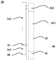
图4是根据本实用新型一个实施例的冷藏冷冻装置1的化霜装置30的部分结构示意图。如图4所示,在该实施例中,化霜装置30还包括驱动组件40。Fig. 4 is a partial structural diagram of the defrosting device 30 of the refrigerating and freezing device 1 according to an embodiment of the present invention. As shown in FIG. 4 , in this embodiment, the defrosting device 30 further includes a driving assembly 40 .

驱动组件40包括设置在循环管路31的外侧的电机41以及与电机41传动连接的传动机构42,传动机构42和支撑件38连接设置,并且驱动组件40配置成在冷藏冷冻装置1正常制冷时使支撑件38位于蓄热段311的底部,在冷藏冷冻装置1启动化霜之后启动电机41以驱动传动带带动支撑件38沿着蓄热段311和连接段312从蓄热段311的底部移动到放热段313的入口39,以将蓄热体32送入放热段313,并在将蓄热体32送入放热段313之后启动电机41并反向工作以驱动传动带带动支撑件38沿着蓄热段311和连接段312从连接段312的顶部移动回蓄热段311的底部,以备在蓄热体32从回流段314流回蓄热段311时使支撑件38可以支撑蓄热体32。The drive assembly 40 includes a motor 41 arranged on the outside of the circulation pipeline 31 and a transmission mechanism 42 connected to the motor 41. The transmission mechanism 42 is connected to the support member 38. Make the support 38 at the bottom of the heat storage section 311, start the motor 41 to drive the transmission belt to drive the support 38 to move from the bottom of the heat storage section 311 to the bottom of the heat storage section 312 along the heat storage section 311 and the connecting section 312 The inlet 39 of the heat release section 313 is to send the heat storage body 32 into the heat release section 313, and after the heat storage body 32 is sent into the heat release section 313, start the motor 41 and work in reverse to drive the transmission belt to drive the support member 38 along the The heat storage section 311 and the connection section 312 move back from the top of the connection section 312 to the bottom of the heat storage section 311, so that the support 38 can support the heat storage when the heat storage body 32 flows back to the heat storage section 311 from the return section 314 body32.

具体地,如图2和图3所示,蓄热段311和连接段312的口径相同,且其内管道的延伸方向均为竖直方向,并且蓄热段311和连接段312之间交界的部分平滑地连接在一起。在此基础上,传动机构42包括与电机41传动连接的传动传动带421和与传动带421传动连接的滑轮422。滑轮422和支撑件38连接设置,并且滑轮422配置成在转动时带动支撑件38在沿着蓄热段311和连接段312内向上或向下移动。Specifically, as shown in FIG. 2 and FIG. 3 , the heat storage section 311 and the connection section 312 have the same caliber, and the extension directions of the inner pipes are both vertical, and the junction between the heat storage section 311 and the connection section 312 Parts are smoothly joined together. On this basis, the transmission mechanism 42 includes a transmission belt 421 that is in transmission connection with the motor 41 and a pulley 422 that is in transmission connection with the transmission belt 421 . The pulley 422 is connected to the support member 38 , and the pulley 422 is configured to drive the support member 38 to move up or down along the heat storage section 311 and the connecting section 312 when rotating.

在冷藏冷冻装置1启动化霜之后,电机41启动,驱动传动带421转动以带动滑轮422转动,带动支撑件38从蓄热段311的底部沿着蓄热段311和连接段312向上移动到连接段312的顶部,即移动到放热段313的入口39处,以将蓄热体32送入放热段313。在此过程中,蓄热体32和支撑件38从图2中示出的位置移动到图3中示出的位置。After the defrosting of the refrigerating and freezing device 1 is started, the motor 41 starts to drive the transmission belt 421 to rotate to drive the pulley 422 to rotate, and the support member 38 is moved from the bottom of the heat storage section 311 to the connection section along the heat storage section 311 and the connecting section 312 The top of 312 moves to the inlet 39 of the heat release section 313 to send the heat accumulator 32 into the heat release section 313. During this process, the heat storage body 32 and the support 38 are moved from the position shown in FIG. 2 to the position shown in FIG. 3 .

在将蓄热体32送入放热段313之后,电机41启动并反向工作,驱动传动带421反向转动以带动滑轮422反向转动,带动支撑件38从连接段312的顶部沿着连接段312和蓄热段311向下移动到蓄热段311的底部,以备在蓄热体32从回流段314流回蓄热段311时使支撑件38再次用于支撑蓄热体32。在此过程中,蓄热体32已经留到放热段313内,且支撑件38从图3中示出的位置移动到图2中示出的位置。至此,驱动组件40完成一个工作周期。After the heat accumulator 32 is sent into the heat release section 313, the motor 41 starts and works in reverse, driving the transmission belt 421 to rotate in reverse to drive the pulley 422 to rotate in reverse, and to drive the support 38 from the top of the connecting section 312 along the connecting section. 312 and the heat storage section 311 move down to the bottom of the heat storage section 311 , so that the support member 38 can be used to support the heat storage body 32 again when the heat storage body 32 flows back to the heat storage section 311 from the return section 314 . During this process, the heat accumulator 32 has been left in the heat release section 313 and the support 38 has moved from the position shown in FIG. 3 to the position shown in FIG. 2 . So far, the driving assembly 40 completes one working cycle.

在一些实施例中,如图3所示,循环管路31在蓄热段311处可以具有不完全封闭的底壁381。如图2所示,支撑件38在冷藏冷冻装置1正常制冷时设置在底壁381上。在另一些实施例中,如图3所示,循环管路31的蓄热段311处的底部可以完全敞开,在冷藏冷冻装置1正常制冷时,支撑件38在驱动组件40的支撑下,稳定地设置在蓄热段311处的底部,直接作为蓄热段311的底壁。In some embodiments, as shown in FIG. 3 , the circulation pipeline 31 may have an incompletely closed bottom wall 381 at the heat storage section 311 . As shown in FIG. 2 , the support member 38 is disposed on the bottom wall 381 when the refrigerating and freezing device 1 is normally refrigerated. In some other embodiments, as shown in FIG. 3 , the bottom of the heat storage section 311 of the circulation pipeline 31 can be completely opened, and when the refrigerating and freezing device 1 is normally refrigerated, the support member 38 is supported by the drive assembly 40 to stabilize It is arranged at the bottom of the heat storage section 311 directly as the bottom wall of the heat storage section 311.

在上述实施例中,支撑件38上开设有允许压机仓与蓄热段311连通的开口。在一个具体实施例中,支撑件38可以为网状结构。支撑件38上开设的开口的最大口径小于蓄热颗粒的最小粒径。也就是说,支撑件38上开设的开口只允许压机仓内的热空气在散热风机23的促使下吹入蓄热体32,不允许蓄热颗粒流出,以在支撑蓄热体32的同时,提高了换热效率。In the above embodiments, the support member 38 is provided with an opening allowing the press chamber to communicate with the heat storage section 311 . In a specific embodiment, the support member 38 may be a mesh structure. The maximum diameter of the opening opened on the support member 38 is smaller than the minimum particle diameter of the heat storage particles. That is to say, the opening that offers on the support member 38 only allows the hot air in the compressor compartment to be blown into the thermal storage body 32 under the impetus of the cooling fan 23, and does not allow the thermal storage particles to flow out, so as to support the thermal storage body 32 while , improving the heat transfer efficiency.

本领域技术人员还应理解,本实用新型实施例中所称的“上”、“下”、“前”、“后”、“顶”、“底”、“竖直”等用于表示方位或位置关系的用语是以冷藏冷冻装置1的实际使用状态为基准而言的,这些用语仅是为了便于描述和理解本实用新型的技术方案,而不是指示或暗示所指的装置或不见必须具有特定的方位、以特定的方位构造和操作,因此不能理解为对本实用新型的限制。Those skilled in the art should also understand that the terms "up", "down", "front", "rear", "top", "bottom" and "vertical" in the embodiments of the present invention are used to indicate orientation The terms or positional relationship are based on the actual use state of the refrigerating and freezing device 1, and these terms are only for the convenience of describing and understanding the technical solution of the present utility model, rather than indicating or implying that the device referred to must have Certain orientations, constructed and operative in certain orientations, therefore are not to be construed as limitations on the invention.

至此,本领域技术人员应认识到,虽然本文已详尽示出和描述了本实用新型的多个示例性实施例,但是,在不脱离本实用新型精神和范围的情况下,仍可根据本实用新型公开的内容直接确定或推导出符合本实用新型原理的许多其他变型或修改。因此,本实用新型的范围应被理解和认定为覆盖了所有这些其他变型或修改。So far, those skilled in the art should recognize that although a number of exemplary embodiments of the present invention have been shown and described in detail herein, they can still be used according to the present invention without departing from the spirit and scope of the present invention. Many other variations or modifications that conform to the principles of the utility model are directly determined or derived from the disclosed content of the new model. Therefore, the scope of the present invention should be understood and deemed to cover all such other variations or modifications.

Claims (10)

1. A refrigeration and freezer comprising:
a housing defining an evaporator chamber and a press cabin therein;
an evaporator disposed within the evaporator chamber; and
a defrosting device comprising a circulation line, wherein the circulation line comprises a heat storage section arranged in the compressor compartment and a heat release section arranged in the evaporator chamber, the circulation line is internally provided with a heat storage body capable of flowing in the circulation line, and the defrosting device is configured to allow the heat storage body to absorb heat in the compressor compartment in the heat storage section and allow the heat storage body to release heat in the heat release section so as to defrost the evaporator.
2. A refrigerating and freezing apparatus according to claim 1, wherein,
the heat release section is sleeved on the evaporator; and is also provided with
The thermal mass includes a plurality of thermal storage particles, wherein the thermal storage particles are sized to flow through the evaporator within the exothermic section.
3. A refrigerating and freezing apparatus according to claim 2, wherein,
the defrosting device further comprises a support, wherein the support is movably arranged in the circulating pipeline and is configured to be positioned at the bottom of the heat storage section to support the heat accumulator when the refrigeration and freezing device is in normal refrigeration, and push the heat accumulator to flow from the heat storage section to the heat release section after the refrigeration and freezing device starts defrosting.
4. A refrigerating and freezing apparatus according to claim 3, wherein,
the circulating pipeline is provided with a bottom wall which is not completely closed at the heat storage section, and the supporting piece is arranged on the bottom wall when the refrigeration and freezing device is used for normal refrigeration; and is also provided with
The support member is provided with an opening allowing the press cabin to be communicated with the heat storage section.
5. A refrigerating and freezing apparatus according to claim 3, wherein,
the circulating pipeline further comprises a connecting section positioned between the heat storage section and the heat release section, wherein the connecting section is positioned at the downstream of the heat storage section in the circulating direction of the heat storage body; and is also provided with
The support is controllably slidable within the thermal storage section and the connecting section.
6. A refrigerating and freezing apparatus according to claim 5, wherein,
the defrosting device further comprises a driving assembly, wherein the driving assembly comprises a motor arranged on the outer side of the circulating pipeline and a transmission mechanism in transmission connection with the motor, the transmission mechanism is connected with the supporting piece, the driving assembly is configured to enable the supporting piece to be located at the bottom of the heat storage section when the refrigerating and freezing device is used for refrigerating normally, and the motor is started after the refrigerating and freezing device is started for defrosting so as to drive the transmission mechanism to drive the supporting piece to move along the heat storage section and the connection section from the bottom of the heat storage section to an inlet of the heat release section so as to send the heat storage body into the heat release section.
7. A refrigerating and freezing apparatus according to claim 5, wherein,
the defrosting device further comprises a first door arranged in the circulating pipeline, wherein the first door is positioned between the heat storage section and the connecting section; and is also provided with
The first door is configured to be in a closed state when the refrigeration chiller is normally refrigerating and to be opened after the refrigeration chiller is started to defrost.
8. A refrigerating and freezing apparatus according to claim 2, wherein,
the defrosting device further comprises a second door arranged in the circulating pipeline, wherein the second door is positioned at the bottom of the evaporator, and an opening for defrosting water to flow down is formed in the second door; and is also provided with
The second door is configured to be in a closed state when the refrigeration and freezing device is normally refrigerating and in a defrosting early stage and to be opened in a defrosting later stage, wherein the defrosting process of the refrigeration and freezing device comprises the defrosting early stage and the defrosting later stage which are sequenced in time sequence.
9. The refrigeration and freezer of claim 8, further comprising:
the water receiving disc is arranged at a position outside the circulating pipeline in the evaporator chamber and is used for receiving defrosting water; and is also provided with
The circulating pipeline is provided with an opening allowing defrosting water to flow into the water receiving disc at the bottom of the heat release section.
10. A refrigerating and freezing apparatus according to claim 1, wherein,
the circulating pipeline further comprises a reflux section positioned between the heat storage section and the heat release section, wherein the reflux section is positioned downstream of the heat release section in the circulating direction of the heat accumulator; and is also provided with
The defrosting device comprises a third door arranged in the circulating pipeline, wherein the third door is positioned between the heat release section and the backflow section, and is configured to be in a closed state when the refrigerating and freezing device is in normal refrigeration and in the defrosting process of the refrigerating and freezing device, and is opened after the refrigerating and freezing device finishes defrosting.
CN202222648065.XU 2022-10-08 2022-10-08 Refrigerating and freezing device Active CN219199624U (en)

Priority Applications (1)

Application Number Priority Date Filing Date Title
CN202222648065.XU CN219199624U (en) 2022-10-08 2022-10-08 Refrigerating and freezing device

Applications Claiming Priority (1)

Application Number Priority Date Filing Date Title
CN202222648065.XU CN219199624U (en) 2022-10-08 2022-10-08 Refrigerating and freezing device

Publications (1)

Publication Number Publication Date
CN219199624U true CN219199624U (en) 2023-06-16

Family

ID=86717500

Family Applications (1)

Application Number Title Priority Date Filing Date
CN202222648065.XU Active CN219199624U (en) 2022-10-08 2022-10-08 Refrigerating and freezing device

Country Status (1)

Country Link
CN (1) CN219199624U (en)

Similar Documents

Publication Publication Date Title
CN104949426B (en) Wind cooling refrigerator
CN102022887A (en) Refrigerator
CN104160224A (en) Refrigerator
CN215951876U (en) Refrigerating and freezing device
CN110006165B (en) Protection device and protection method for low-temperature defrosting and high-temperature prevention and air conditioner
US20070101730A1 (en) Cold stocker
CN110645760A (en) Energy storage type air-cooled frost-free refrigerator and defrosting method thereof
CN102620502A (en) Refrigeration module for refrigerators
CN109974368A (en) A kind of ducting system and refrigerator
CN114440530A (en) A kind of refrigerator utilizing refrigerator compartment to defrost
CN104823010B (en) Refrigerator
JP3826998B2 (en) Stirling refrigeration system and Stirling refrigerator
CN100572999C (en) Built-in type refrigerator
CN111197901A (en) Refrigerator and air duct structure
CN210220360U (en) refrigerator
CN101065626B (en) Working method of air direct cooling combined multi-temperature control refrigerator with ice maker
CN110671865A (en) Parallel double-circulation refrigerator and control method thereof
CN110762936A (en) Heat accumulation defrosting system for cold storage air cooler and cold storage
CN206131589U (en) Air -cooling refrigerator
CN115597285A (en) Cold-storage refrigerating device
CN219063813U (en) An evaporator assembly and a refrigerator
CN202547237U (en) Refrigeration module of refrigerator
CN110736292A (en) Multi-temperature-zone refrigerator air duct system and multi-temperature-zone refrigerator
CN114688795B (en) refrigerator
CN113701429B (en) Refrigerator and control method thereof

Legal Events

Date Code Title Description
GR01 Patent grant
GR01 Patent grant