CN219189134U - Fixing device convenient to angle regulation's front fork welding of bicycle uses - Google Patents
Fixing device convenient to angle regulation's front fork welding of bicycle uses Download PDFInfo
- Publication number
- CN219189134U CN219189134U CN202223383427.3U CN202223383427U CN219189134U CN 219189134 U CN219189134 U CN 219189134U CN 202223383427 U CN202223383427 U CN 202223383427U CN 219189134 U CN219189134 U CN 219189134U
- Authority
- CN
- China
- Prior art keywords
- fixedly connected
- front fork
- welding
- fixing device
- worm
- Prior art date
- Legal status (The legal status is an assumption and is not a legal conclusion. Google has not performed a legal analysis and makes no representation as to the accuracy of the status listed.)
- Expired - Fee Related
Links
- 238000003466 welding Methods 0.000 title claims abstract description 31
- 230000007246 mechanism Effects 0.000 claims abstract description 49
- 238000009434 installation Methods 0.000 claims description 9
- 239000006260 foam Substances 0.000 claims description 5
- 238000003825 pressing Methods 0.000 description 5
- 238000010586 diagram Methods 0.000 description 4
- 238000000034 method Methods 0.000 description 3
- 230000008569 process Effects 0.000 description 2
- 230000009286 beneficial effect Effects 0.000 description 1
- 230000008859 change Effects 0.000 description 1
- 238000004519 manufacturing process Methods 0.000 description 1
- 238000012986 modification Methods 0.000 description 1
- 230000004048 modification Effects 0.000 description 1
Images

Classifications
-
- Y—GENERAL TAGGING OF NEW TECHNOLOGICAL DEVELOPMENTS; GENERAL TAGGING OF CROSS-SECTIONAL TECHNOLOGIES SPANNING OVER SEVERAL SECTIONS OF THE IPC; TECHNICAL SUBJECTS COVERED BY FORMER USPC CROSS-REFERENCE ART COLLECTIONS [XRACs] AND DIGESTS
- Y02—TECHNOLOGIES OR APPLICATIONS FOR MITIGATION OR ADAPTATION AGAINST CLIMATE CHANGE
- Y02T—CLIMATE CHANGE MITIGATION TECHNOLOGIES RELATED TO TRANSPORTATION
- Y02T10/00—Road transport of goods or passengers
- Y02T10/10—Internal combustion engine [ICE] based vehicles
- Y02T10/40—Engine management systems
Landscapes
- Butt Welding And Welding Of Specific Article (AREA)
Abstract
Description
技术领域technical field
本实用新型涉及焊接工装技术领域,尤其涉及一种便于调整角度的自行车前叉焊接用固定装置。The utility model relates to the technical field of welding tooling, in particular to a fixing device for welding a bicycle front fork which is convenient for angle adjustment.
背景技术Background technique
前叉组件在自行车结构中处于前方部位,它的上端与车把部件相连,车架部件与前管配合,下端与前轴部件配合,组成自行车的导向系统。转动车把和前叉,可以使前轮改变方向,起到了自行车的导向作用。此外,还可以起到控制自行车行驶的作用。The front fork assembly is in the front position in the bicycle structure, its upper end is connected with the handlebar part, the vehicle frame part is matched with the front tube, and the lower end is matched with the front axle part to form the guiding system of the bicycle. Turning the handlebar and front fork can change the direction of the front wheel and play a guiding role in the bicycle. In addition, it can also play a role in controlling the bicycle.
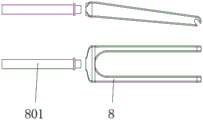
如图1所示,自行车前叉由叉腿8和竖管801组成,焊接加工时,通过将竖管801插在叉腿8设置的开孔内,随后对其进行焊接;现有技术中,自行车前叉焊接用固定装置在使用过程中不便于对自行车前叉进行转动,而在焊接前叉部件时,需要对连接部位进行整周焊接,导致加工人员只能反复装夹调整前叉部件的角度,使用起来十分不便。As shown in Figure 1, the bicycle front fork is made up of
实用新型内容Utility model content
本实用新型的目的是为了解决现有技术中存在的缺点,而提出的一种便于调整角度的自行车前叉焊接用固定装置。The purpose of the utility model is to solve the shortcomings in the prior art, and propose a bicycle front fork welding fixing device that is convenient for angle adjustment.
为了实现上述目的,本实用新型采用了如下技术方案:一种便于调整角度的自行车前叉焊接用固定装置,包括底座,所述底座上侧通过转动机构转动连接有转盘,所述转盘上表面一侧固定连接有立板,所述立板一侧固定连接有夹持机构,所述立板一侧位于夹持机构下侧固定连接有支撑架,所述立板中部设置有滑槽,所述滑槽内安装有调节机构,所述底座上表面一侧固定连接有立柱,所述立柱一侧通过抵紧调节组件固定连接有竖管固定机构,所述竖管固定机构夹槽与转盘同轴设置。In order to achieve the above object, the utility model adopts the following technical scheme: a bicycle front fork welding fixing device that is easy to adjust the angle, including a base, the upper side of the base is connected with a turntable through a rotating mechanism, and the upper surface of the turntable is a One side of the vertical plate is fixedly connected with a vertical plate, one side of the vertical plate is fixedly connected with a clamping mechanism, one side of the vertical plate is fixedly connected with a support frame at the lower side of the clamping mechanism, the middle part of the vertical plate is provided with a chute, the An adjustment mechanism is installed in the chute, one side of the upper surface of the base is fixedly connected with a column, and one side of the column is fixedly connected with a standpipe fixing mechanism by pressing the adjustment assembly, and the clamping groove of the standpipe fixing mechanism is coaxial with the turntable set up.
作为上述技术方案的进一步描述:As a further description of the above technical solution:
所述转动机构包括蜗轮和蜗杆,所述底座上表面一侧设置有安装槽,所述转盘下表面中部固定连接有支撑柱,所述支撑柱底端转动连接在安装槽底壁,所述蜗轮中部固定连接在支撑柱外壁,所述蜗杆转动连接在安装槽一侧,所述蜗轮和蜗杆啮合连接,所述蜗杆一端贯穿底座延伸至外部并固定连接有摇把。The rotating mechanism includes a worm wheel and a worm screw. An installation groove is provided on one side of the upper surface of the base. A support column is fixedly connected to the middle part of the lower surface of the turntable. The bottom end of the support column is rotatably connected to the bottom wall of the installation groove. The worm wheel The middle part is fixedly connected to the outer wall of the supporting column, the worm is rotatably connected to one side of the installation groove, the worm gear and the worm are meshed and connected, and one end of the worm extends through the base to the outside and is fixedly connected with a handle.
作为上述技术方案的进一步描述:As a further description of the above technical solution:
所述夹持机构包括固定座,所述固定座一侧固定连接在立板一侧,所述固定座中部转动连接有双头螺杆,所述双头螺杆两侧螺纹外壁均螺纹连接有夹块。The clamping mechanism includes a fixed seat, one side of the fixed seat is fixedly connected to one side of the vertical plate, the middle part of the fixed seat is rotatably connected with a double-ended screw, and the threaded outer walls on both sides of the double-ended screw are threaded with clamping blocks .
作为上述技术方案的进一步描述:As a further description of the above technical solution:
两个所述夹块相远离面一侧均设置有缓冲泡棉。The sides of the two clamping blocks facing away from each other are provided with cushioning foam.
作为上述技术方案的进一步描述:As a further description of the above technical solution:
所述双头螺杆一端固定连接有防滑旋钮。An anti-slip knob is fixedly connected to one end of the double-ended screw.
作为上述技术方案的进一步描述:As a further description of the above technical solution:
所述调节机构包括支撑块,所述支撑块一侧中部固定连接有滑块,所述滑块外壁滑动连接在滑槽内壁,所述滑块远离支撑块一侧设置有凸板,所述凸板中部螺纹连接有紧固螺杆。The adjustment mechanism includes a support block, the middle part of one side of the support block is fixedly connected with a slider, the outer wall of the slider is slidably connected to the inner wall of the chute, and the side of the slider away from the support block is provided with a convex plate. The middle part of the plate is threadedly connected with a fastening screw.
本实用新型具有如下有益效果:The utility model has the following beneficial effects:
本实用新型设计的自行车前叉焊接治具在对自行车前叉进行焊接作业固定时,便于调整前叉部件的角度,方便操作人员进行焊接加工。The bicycle front fork welding jig designed by the utility model is convenient to adjust the angle of the front fork parts when the bicycle front fork is welded and fixed, and is convenient for operators to carry out welding processing.
附图说明Description of drawings
图1为现有技术中自行车前叉结构示意图;Fig. 1 is a schematic diagram of the structure of a bicycle front fork in the prior art;
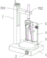
图2为本实用新型提出的一种便于调整角度的自行车前叉焊接用固定装置的立体图;Fig. 2 is a perspective view of a bicycle front fork welding fixing device that is convenient for angle adjustment proposed by the utility model;
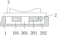
图3为本实用新型提出的一种便于调整角度的自行车前叉焊接用固定装置的转动机构结构示意图;Fig. 3 is a structural schematic diagram of a rotating mechanism of a bicycle front fork welding fixing device that is convenient for angle adjustment proposed by the utility model;
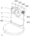
图4为本实用新型提出的一种便于调整角度的自行车前叉焊接用固定装置的夹持机构结构示意图;Fig. 4 is a structural schematic diagram of the clamping mechanism of a bicycle front fork welding fixing device that is convenient for angle adjustment proposed by the utility model;
图5为本实用新型提出的一种便于调整角度的自行车前叉焊接用固定装置的调节机构结构示意图。Fig. 5 is a structural schematic diagram of an adjustment mechanism of a bicycle front fork welding fixing device proposed by the utility model to facilitate angle adjustment.
图例说明:illustration:
1、底座;101、安装槽;2、转动机构;201、蜗轮;202、蜗杆;3、转盘;301、支撑柱;4、立板;401、支撑架;402、滑槽;5、夹持机构;501、固定座;502、双头螺杆;503、夹块;504、缓冲泡棉;505、防滑旋钮;6、调节机构;601、支撑块;602、滑块;603、紧固螺杆;7、立柱;701、抵紧调节组件;702、竖管固定机构;8、叉腿;801、竖管。1. Base; 101. Mounting groove; 2. Rotating mechanism; 201. Worm wheel; 202. Worm; 3. Turntable; 301. Support column; Mechanism; 501, fixed seat; 502, double-headed screw; 503, clamp block; 504, buffer foam; 505, anti-slip knob; 6, adjustment mechanism; 601, support block; 602, slider; 603,
具体实施方式Detailed ways
下面将结合本实用新型实施例中的附图,对本实用新型实施例中的技术方案进行清楚、完整地描述,显然,所描述的实施例仅仅是本实用新型一部分实施例,而不是全部的实施例。基于本实用新型中的实施例,本领域普通技术人员在没有做出创造性劳动前提下所获得的所有其他实施例,都属于本实用新型保护的范围。The technical solutions in the embodiments of the present invention will be clearly and completely described below in conjunction with the accompanying drawings in the embodiments of the present invention. Obviously, the described embodiments are only part of the embodiments of the present invention, not all of them. example. Based on the embodiments of the present utility model, all other embodiments obtained by persons of ordinary skill in the art without making creative efforts belong to the scope of protection of the present utility model.
参照图1-5,本实用新型提供的一种实施例:一种便于调整角度的自行车前叉焊接用固定装置,包括底座1,底座1上侧通过转动机构2转动连接有转盘3,转盘3上表面一侧固定连接有立板4,立板4一侧固定连接有夹持机构5,立板4一侧位于夹持机构5下侧固定连接有支撑架401;Referring to Figures 1-5, an embodiment provided by the present invention is a bicycle front fork welding fixing device that is convenient for angle adjustment, including a
立板4中部设置有滑槽402,滑槽402内设置有调节机构6,底座1上表面一侧固定连接有立柱7,立柱7一侧通过抵紧调节组件701固定连接有竖管固定机构702,竖管固定机构702夹槽与转盘3同轴设置;The middle part of the
其中,通过设置的夹持机构5配合支撑架401可对自行车前叉叉腿8进行夹持固定,使得便于将竖管801与叉腿8进行焊接;Wherein, the
通过设置的转动机构2与转盘3相互配合使用,使得在通过夹持机构5对叉腿8夹持固定进行焊接时,便于对叉腿8进行旋转角度,从而便于对其进行焊接;The
通过设置的调节机构6与抵紧调节组件701和竖管固定机构702相配合使用,进行焊接时,首先将竖管801通过竖管固定机构702进行夹持固定,随即通过抵紧调节组件701将竖管801向下调节,调节机构6对叉腿8配合孔位置进行调节,使得叉腿8与竖管801之间进行配合,提高焊接精度。The
转动机构2包括蜗轮201和蜗杆202,底座1上表面一侧设置有安装槽101,转盘3下表面中部固定连接有支撑柱301,支撑柱301底端转动连接在安装槽101底壁,蜗轮201中部固定连接在支撑柱301外壁,蜗杆202转动连接在安装槽101一侧,蜗轮201和蜗杆202啮合连接,蜗杆202一端贯穿底座1延伸至外部并固定连接有摇把;The
其中,通过旋动摇把带动蜗杆202旋转,蜗杆202旋转带动蜗轮201旋转,蜗轮201旋转通过支撑柱301带动转盘3旋转,从而带动立板4以及设置在立板4上的叉腿8进行旋转,进而实现自行车前叉焊接的角度调节。Wherein, by rotating the handle, the
夹持机构5包括固定座501,固定座501一侧固定连接在立板4一侧,固定座501中部转动连接有双头螺杆502,双头螺杆502两侧螺纹外壁均螺纹连接有夹块503;The
其中,通过旋动双头螺杆502带动两侧设置有螺纹孔的夹块503相对靠近或远离,从而实现对叉腿8的夹持固定。Wherein, by rotating the double-
两个夹块503相远离面一侧均设置有缓冲泡棉504;
其中,通过设置的缓冲泡棉504,使得在通过夹持机构5对叉腿8进行夹持固定时,防止夹块503与叉腿8直接接触导致的叉腿8表面遭损坏,进而提高了产品生产质量。Wherein, through the
双头螺杆502一端固定连接有防滑旋钮505;One end of the double-
其中,通过设置的防滑旋钮505,使得便于对双头螺杆502进行旋转。Wherein, the
调节机构6包括支撑块601,支撑块601一侧中部固定连接有滑块602,滑块602外壁滑动连接在滑槽402内壁,滑块602远离支撑块601一侧设置有凸板,凸板中部螺纹连接有紧固螺杆603;The
其中,通过滑块602在滑槽402内滑动,从而带动支撑块601位置进行上下移动,同时支撑块601与叉腿8接触,从而实现对叉腿8与立板4之间角度调节,进而实现对叉腿8配合孔位置的调节。Wherein, the sliding
工作原理:具体应用时,在进行焊接作业前,首先通过将叉腿8通过夹持机构5和支撑架401之间配合进行夹持,具体操作时,通过将叉腿8端部槽置于支撑架401外壁,随后通过旋动防滑旋钮505带动双头螺杆502在固定座501中部旋转,从而带动双头螺杆502两侧螺纹外壁上分别设置有螺纹孔的夹块503相对远离,从而使得通过从叉腿8中部向外顶夹住叉腿8,夹持过程中,先对叉腿8进行预夹持,随后将竖管801通过竖管固定机构702进行夹持固定,随后通过抵紧调节组件701带动竖管固定机构702以及竖管801高度向下,快接近叉腿8时,通过调节机构6中滑块602在滑槽402内滑动,从而带动支撑块601位置进行上下移动,同时支撑块601与叉腿8接触,从而实现将叉腿8配合孔位置进行调节,使得叉腿8配合孔与竖管801同轴,随后通过抵紧调节组件701带动竖管801插入叉腿8配合孔内,随后通过夹持机构5进行紧固夹持,随即可对叉腿8与竖管801进行焊接,焊接过程中,需要进行角度调节,即将自行车前叉进行旋转一定角度方便进行焊接时,通过旋动摇把带动蜗杆202旋转,蜗杆202旋转带动蜗轮201旋转,蜗轮201旋转通过支撑柱301带动转盘3旋转,从而带动立板4以及设置在立板4上的叉腿8进行旋转,进而实现自行车前叉焊接的角度调节。Working principle: In specific applications, before welding, the
最后应说明的是:以上所述仅为本实用新型的优选实施例而已,并不用于限制本实用新型,尽管参照前述实施例对本实用新型进行了详细的说明,对于本领域的技术人员来说,其依然可以对前述各实施例所记载的技术方案进行修改,或者对其中部分技术特征进行等同替换,凡在本实用新型的精神和原则之内,所作的任何修改、等同替换、改进等,均应包含在本实用新型的保护范围之内。Finally, it should be noted that: the above is only a preferred embodiment of the utility model, and is not intended to limit the utility model, although the utility model has been described in detail with reference to the foregoing embodiments, for those skilled in the art , it can still modify the technical solutions recorded in the foregoing embodiments, or perform equivalent replacements on some of the technical features. Any modifications, equivalent replacements, improvements, etc. made within the spirit and principles of the present utility model, All should be included within the protection scope of the present utility model.
Claims (6)
Priority Applications (1)
| Application Number | Priority Date | Filing Date | Title |
|---|---|---|---|
| CN202223383427.3U CN219189134U (en) | 2022-12-16 | 2022-12-16 | Fixing device convenient to angle regulation's front fork welding of bicycle uses |
Applications Claiming Priority (1)
| Application Number | Priority Date | Filing Date | Title |
|---|---|---|---|
| CN202223383427.3U CN219189134U (en) | 2022-12-16 | 2022-12-16 | Fixing device convenient to angle regulation's front fork welding of bicycle uses |
Publications (1)
| Publication Number | Publication Date |
|---|---|
| CN219189134U true CN219189134U (en) | 2023-06-16 |
Family
ID=86709781
Family Applications (1)
| Application Number | Title | Priority Date | Filing Date |
|---|---|---|---|
| CN202223383427.3U Expired - Fee Related CN219189134U (en) | 2022-12-16 | 2022-12-16 | Fixing device convenient to angle regulation's front fork welding of bicycle uses |
Country Status (1)
| Country | Link |
|---|---|
| CN (1) | CN219189134U (en) |
-
2022
- 2022-12-16 CN CN202223383427.3U patent/CN219189134U/en not_active Expired - Fee Related
Similar Documents
| Publication | Publication Date | Title |
|---|---|---|
| CN117020546B (en) | Gear welding tool | |
| CN211305386U (en) | Adjustable radiator welding jig | |
| CN202780248U (en) | Laser welding positioning fixture | |
| CN115635236A (en) | Fixing tool for welding of car seat back frame | |
| CN115401484A (en) | Detachable machine tool double-station clamping device capable of avoiding loosening | |
| CN213470146U (en) | Automobile parts welds dress anchor clamps | |
| CN213105647U (en) | Boring and milling machining center for machining high-pressure pump body | |
| CN219074773U (en) | Car frame welds anchor clamps | |
| CN211804578U (en) | Welding device for processing LED lamp | |
| CN116682746B (en) | Bonding wire workbench of chip multi-station welding machine and application method thereof | |
| CN113618289B (en) | Automatic welding device for steel structure shell | |
| CN108971875A (en) | A kind of clamping device for welding robot | |
| CN223235382U (en) | A plane annular welding device for automobile welding parts | |
| CN222199748U (en) | Adjustable positioning processing seat for processing automobile sheet metal parts | |
| CN114951771A (en) | Arc surface processing equipment | |
| CN220661060U (en) | Clamping mechanism | |
| CN214418048U (en) | A welding positioning device that is easy to adjust the angle | |
| CN219724995U (en) | Laser welding robot | |
| CN220659694U (en) | Bicycle rim welding equipment | |
| CN219582260U (en) | Clamping mechanism of horizontal sawing machine for seamless steel pipes | |
| CN222386683U (en) | Polishing machine for metal material processing | |
| CN221415605U (en) | Tube plate welding auxiliary device suitable for different styles | |
| CN213733491U (en) | Laser and ultrasonic plastic seamless welding clamp | |
| CN222079200U (en) | A tooling structure for producing compressor parts | |
| CN220479968U (en) | Auxiliary die mounting device for pipe making machine |
Legal Events
| Date | Code | Title | Description |
|---|---|---|---|
| GR01 | Patent grant | ||
| GR01 | Patent grant | ||
| CF01 | Termination of patent right due to non-payment of annual fee |
Granted publication date: 20230616 |
|
| CF01 | Termination of patent right due to non-payment of annual fee |