CN219188818U - Pipe cutting machine convenient to clamp - Google Patents
Pipe cutting machine convenient to clamp Download PDFInfo
- Publication number
- CN219188818U CN219188818U CN202221936035.2U CN202221936035U CN219188818U CN 219188818 U CN219188818 U CN 219188818U CN 202221936035 U CN202221936035 U CN 202221936035U CN 219188818 U CN219188818 U CN 219188818U
- Authority
- CN
- China
- Prior art keywords
- cavity
- fixed
- hole
- moving
- block
- Prior art date
- Legal status (The legal status is an assumption and is not a legal conclusion. Google has not performed a legal analysis and makes no representation as to the accuracy of the status listed.)
- Expired - Fee Related
Links
Images


Classifications
-
- Y—GENERAL TAGGING OF NEW TECHNOLOGICAL DEVELOPMENTS; GENERAL TAGGING OF CROSS-SECTIONAL TECHNOLOGIES SPANNING OVER SEVERAL SECTIONS OF THE IPC; TECHNICAL SUBJECTS COVERED BY FORMER USPC CROSS-REFERENCE ART COLLECTIONS [XRACs] AND DIGESTS
- Y02—TECHNOLOGIES OR APPLICATIONS FOR MITIGATION OR ADAPTATION AGAINST CLIMATE CHANGE
- Y02P—CLIMATE CHANGE MITIGATION TECHNOLOGIES IN THE PRODUCTION OR PROCESSING OF GOODS
- Y02P70/00—Climate change mitigation technologies in the production process for final industrial or consumer products
- Y02P70/10—Greenhouse gas [GHG] capture, material saving, heat recovery or other energy efficient measures, e.g. motor control, characterised by manufacturing processes, e.g. for rolling metal or metal working
Landscapes
- Punching Or Piercing (AREA)
Abstract
一种便于夹紧的管材切割机,包括底座、液压杆、支撑板和切割电机、内腔、第一滑槽、气缸、连杆、移动柱和固定块,固定块与移动柱的顶端均固定有安装块,安装块的顶端可拆卸连接有卡板,卡板的底端固定有插块,插块上开设有连接孔,安装块的顶端开设有可供插块插入的插槽,安装块的内部开设有空腔,空腔与插槽之间连通有与连接孔对应的通孔,空腔内滑动连接有插销,插销的一端位于空腔内,插销的另一端通过通孔穿入连接孔内,空腔内还设置有用于移动插销移动结构。本实用新型能够快捷方便地更换卡板。
A pipe cutting machine that is easy to clamp, including a base, a hydraulic rod, a support plate, a cutting motor, an inner cavity, a first chute, a cylinder, a connecting rod, a moving column and a fixed block, and the fixed block and the top of the moving column are both fixed There is a mounting block, the top of the mounting block is detachably connected with a clamping plate, the bottom of the clamping plate is fixed with an inserting block, a connection hole is opened on the inserting block, and a slot for inserting the inserting block is opened at the top of the mounting block, the mounting block There is a cavity inside, and a through hole corresponding to the connection hole is communicated between the cavity and the slot. A pin is slidably connected to the cavity. One end of the pin is located in the cavity, and the other end of the pin is penetrated through the through hole to connect In the hole, the cavity is also provided with a moving structure for moving the bolt. The utility model can quickly and conveniently replace the clamping board.
Description
技术领域technical field
本实用新型涉及管材切割设备技术领域,具体为一种便于夹紧的管材切割机。The utility model relates to the technical field of pipe cutting equipment, in particular to a pipe cutting machine which is convenient for clamping.
背景技术Background technique
管材就是用于做管件的材料,不同的管件要用不同的管材,管材的好坏直接决定了管件的质量,建筑工程、电厂、化工厂等多用此类管材。Pipe is the material used to make pipe fittings. Different pipe fittings use different pipe materials. The quality of the pipe directly determines the quality of the pipe fittings. Construction projects, power plants, chemical plants, etc. often use this type of pipe.
在管材加工过程中需要使用到管材切割机,目前现有的管材切割机,切割质量低,当人们在使用管材切割机时,无法对管材两端进行夹持,导致管材在切断时因重力影响向下倾斜,造成切割面不平整,不方便人们使用,降低了管材切割机的实用性。A pipe cutting machine is needed in the pipe processing process. The current existing pipe cutting machines have low cutting quality. When people use the pipe cutting machine, they cannot clamp the two ends of the pipe, which causes the pipe to be cut due to the influence of gravity. The downward slope causes the cutting surface to be uneven, which is inconvenient for people to use and reduces the practicability of the pipe cutting machine.
授权公告号为CN210305963U的中国专利公开了一种切割质量高的管材切割机,包括底座,底座顶部左侧的前侧和后侧均固定连接有固定块,固定块的顶部固定连接有第一卡板,底座内腔的正面和背面均设置有限位装置,底座内腔的底部设置有滑动装置。该实用新型通过设置底座、固定块、第一卡板、限位装置、滑动装置、驱动装置、移动板、移动柱、第二卡板、液压杆、支撑板和切割电机的相互配合,达到了切割质量高的优点,解决了现有的管材切割机切割质量低的问题,当人们在使用管材切割机时,可以对管材两端进行夹持,不会导致管材在切断时因重力影响向下倾斜,造成切割面不平整,方便了人们使用,提高了管材切割机的实用性。The Chinese patent with the authorized notification number CN210305963U discloses a pipe cutting machine with high cutting quality, including a base, the front and rear sides of the top left side of the base are fixedly connected with a fixed block, and the top of the fixed block is fixedly connected with a first card. The plate, the front and the back of the inner cavity of the base are provided with limiting devices, and the bottom of the inner cavity of the base is provided with a sliding device. The utility model achieves the goal of cutting through the mutual cooperation of the base, the fixed block, the first clamping plate, the limiting device, the sliding device, the driving device, the moving plate, the moving column, the second clamping plate, the hydraulic rod, the supporting plate and the cutting motor. The advantage of high cutting quality solves the problem of low cutting quality of the existing pipe cutting machine. When people use the pipe cutting machine, they can clamp both ends of the pipe, so that the pipe will not be cut downward due to the influence of gravity. The inclination causes the cutting surface to be uneven, which is convenient for people to use and improves the practicability of the pipe cutting machine.
但是,在该实用新型中第一卡板和第二卡板分均为固定连接,当因第一卡板和第二卡板出现损坏、管材过大或者过小导致第一卡板和第二卡板无法有效地夹紧管材等原因,需要更换第一卡板和第二卡板时,无法便捷地更换第一卡板和第二卡板。However, in this utility model, the first clamp and the second clamp are both fixedly connected. When the first clamp and the second clamp are damaged, the pipe is too large or too small, the first clamp and the second clamp Due to reasons such as the inability of the clamping plates to effectively clamp the pipe material, when the first clamping plate and the second clamping plate need to be replaced, the first clamping plate and the second clamping plate cannot be easily replaced.
因此,本实用新型提出一种技术方案来解决上述的无法便捷地更换卡板的问题。Therefore, the utility model proposes a technical solution to solve the above-mentioned problem that the clamp cannot be easily replaced.
实用新型内容Utility model content
针对现有技术存在的不足,本实用新型的目的是提供一种便于夹紧的管材切割机,旨在达到卡板与安装块可拆卸连接,从而方便卡板的拆装的技术效果。Aiming at the shortcomings of the existing technology, the purpose of this utility model is to provide a pipe cutting machine that is easy to clamp, aiming at achieving the technical effect of detachable connection between the clamping plate and the mounting block, thereby facilitating the disassembly and assembly of the clamping plate.
一种便于夹紧的管材切割机,包括底座、液压杆、支撑板和切割电机,所述底座的内部开设有内腔,所述内腔的顶端腔壁上开设有两个通向底座外部的第一滑槽,所述内腔内安装有气缸,所述气缸的活塞杆上固定有与其垂直设置的连杆,所述连杆的顶端前后两侧均固定有移动柱,两根所述移动柱分别对应两个第一滑槽,所述移动柱沿着第一滑槽滑动且其顶端穿出第一滑槽,所述底座的顶端还固定有两块固定块,两块固定块分别对应两根移动柱,所述固定块与移动柱的顶端均固定有安装块,所述安装块的顶端可拆卸连接有卡板,所述卡板的底端固定有插块,所述插块上开设有连接孔,所述安装块的顶端开设有可供插块插入的插槽,所述安装块的内部开设有空腔,所述空腔与插槽之间连通有与连接孔对应的通孔,所述空腔内滑动连接有插销,所述插销的一端位于空腔内,所述插销的另一端通过通孔穿入连接孔内,所述空腔内还设置有用于移动插销移动结构。A pipe cutting machine that is convenient for clamping, including a base, a hydraulic rod, a support plate and a cutting motor. An inner cavity is opened inside the base, and two holes leading to the outside of the base are opened on the top cavity wall of the inner cavity. The first chute, the inner cavity is equipped with a cylinder, the piston rod of the cylinder is fixed with a connecting rod perpendicular to it, the top of the connecting rod is fixed on the front and rear sides, and the two moving columns The columns correspond to the two first chute respectively, the moving column slides along the first chute and its top end passes through the first chute, and the top of the base is also fixed with two fixed blocks, which respectively correspond to Two moving columns, the top of the fixed block and the moving column are fixed with a mounting block, the top of the mounting block is detachably connected with a clamping plate, the bottom of the clamping plate is fixed with an inserting block, and the inserting block is There is a connection hole, the top of the installation block is provided with a slot that can be inserted into the block, the inside of the installation block is provided with a cavity, and there is a communication channel corresponding to the connection hole between the cavity and the slot. hole, the cavity is slidably connected with a pin, one end of the pin is located in the cavity, the other end of the pin penetrates into the connection hole through the through hole, and a moving structure for moving the pin is also arranged in the cavity .
通过采用上述技术方案,当需要拆卸卡板时,通过移动结构移动插销,使插销缩回空腔内,插销上原本通过通孔插入连接孔的一端从连接孔中抽出,此时插块不再被固定在插槽内,向上移动插块即可将插块从插槽中拔出,从而将卡板从安装块上拆下。同理,当需要安装卡板时,先通过移动结构使插销缩回空腔内,再将插块插入插槽内,当插块完全插入插槽内后,连接孔与通孔的位置对应,最后通过移动结构使插销重新通过通孔插入连接孔中即可将插块固定在插槽内,从而将卡板固定安装在安装块上。本实用新型能够快捷方便地更换卡板。By adopting the above-mentioned technical scheme, when the clamping board needs to be disassembled, the plug pin is moved by the moving structure, so that the plug pin is retracted into the cavity, and the end of the plug pin originally inserted into the connection hole through the through hole is pulled out from the connection hole, and the plug block is no longer It is fixed in the slot, and the plug can be pulled out from the slot by moving the plug up, so that the card board can be removed from the mounting block. In the same way, when the card board needs to be installed, first retract the latch into the cavity by moving the structure, and then insert the plug into the slot. When the plug is completely inserted into the slot, the position of the connecting hole corresponds to the through hole. Finally, by moving the structure, the plug pin can be inserted into the connection hole through the through hole again to fix the plug block in the slot, thereby fixing the card board on the mounting block. The utility model can quickly and conveniently replace the clamping board.
本实用新型的进一步设置:所述空腔的顶端腔壁上开设有通向底座外部的第一滑孔,所述移动结构包括移动块和推杆,所述移动块滑动连接于空腔内,所述移动块的一侧与插销固定连接且设置有第一倾斜面,所述移动块的另一侧与空腔的腔壁之间固定连接有第一弹簧,所述推杆的顶端位于底座的上方,所述推杆的底端通过第一滑孔穿入空腔内且设置有与第一倾斜面相匹配的第二倾斜面。Further setting of the utility model: the first sliding hole leading to the outside of the base is opened on the top wall of the cavity, the moving structure includes a moving block and a push rod, and the moving block is slidably connected in the cavity, One side of the moving block is fixedly connected with the latch and is provided with a first inclined surface, the other side of the moving block is fixedly connected with the wall of the cavity with a first spring, and the top end of the push rod is located on the base above, the bottom end of the push rod penetrates into the cavity through the first sliding hole and is provided with a second inclined surface matching the first inclined surface.
通过采用上述技术方案,当需要通过移动结构移动插销,使插销缩回空腔内时,向下按压推杆,推杆沿着第一滑孔向下移动,第二倾斜面按压在第一倾斜面上,按压在第一倾斜面上的力可以分解为横向的力,在该力的作用下移动块沿着空腔朝背向插块的方向滑动,移动块带动插销缩回空腔内,插销从连接孔中抽出。且此时,第一弹簧被压缩形成朝向插块的反弹力。当需要通过移动结构使插销重新插入连接孔中时,松开按压在推杆上力,移动块在第一弹簧的反弹力的作用下即可沿着空腔朝向插块移动,从而带动插销重新插入连接孔内。By adopting the above technical solution, when it is necessary to move the bolt through the moving structure to retract the bolt into the cavity, press the push rod downward, the push rod moves downward along the first sliding hole, and the second inclined surface is pressed against the first inclined surface. On the surface, the force pressed on the first inclined surface can be decomposed into a lateral force. Under the action of this force, the moving block slides along the cavity towards the direction away from the inserting block, and the moving block drives the latch to retract into the cavity. The pin is extracted from the connecting hole. And at this time, the first spring is compressed to form a rebound force toward the plug. When it is necessary to reinsert the bolt into the connection hole through the moving structure, release the pressure on the push rod, and the moving block can move toward the plug along the cavity under the rebound force of the first spring, thereby driving the bolt to reinsert. Insert into the connecting hole.
本实用新型的进一步设置:所述第一滑孔的两侧孔壁上均开设有第二滑槽,所述推杆上固定有用于插入第二滑槽且在第二滑槽内滑动的滑块。Further setting of the present utility model: the hole walls on both sides of the first sliding hole are provided with second sliding grooves, and the push rod is fixed with a sliding sliding groove for inserting into the second sliding groove and sliding in the second sliding groove. piece.
通过采用上述技术方案,推杆在上下移动的过程中,滑块在第二滑槽内上下滑动,一方面提升推杆上下移动时的稳定性,另一方面当滑块与第二滑槽的槽壁接触时,推杆无法继续移动,从而防止推杆从第一滑孔内脱离。By adopting the above technical solution, when the push rod moves up and down, the slider slides up and down in the second chute, on the one hand, the stability of the push rod when moving up and down is improved, and on the other hand, when the slider and the second chute When the groove walls are in contact, the push rod cannot continue to move, thereby preventing the push rod from breaking away from the first sliding hole.
本实用新型的进一步设置:所述空腔的顶端腔壁上开设有通向底座外部的插孔,所述移动结构包括定滑轮和滑套,所述定滑轮通过销轴转动连接于空腔的前后两侧腔壁上,所述滑套固定于空腔的底侧腔壁上且位于定滑轮与通孔之间,所述滑套上靠近通孔的一端开设有第三滑槽,所述第三滑槽的槽底开设有通向滑套外部的第二滑孔,所述插销上背离插块的一端以滑动连接的方式插入第三滑槽内且固定有滑杆,所述滑杆的外部套设有第二弹簧,所述第二弹簧的一端与插销固定连接,所述第二弹簧的另一端与第三滑槽的槽底壁固定连接,所述滑杆的另一端通过第二滑孔穿出滑套且固定有拉绳,所述拉绳的另一端绕过定滑轮且固定有用于插入插孔的堵头,所述堵头的顶端穿出插孔且固定有限位板,所述拉绳上位于定滑轮与滑套之间的部分呈水平状,所述拉绳上位于堵头与定滑轮之间的部分呈竖直状。Further setting of the present utility model: the cavity wall at the top of the cavity is provided with a socket leading to the outside of the base, the moving structure includes a fixed pulley and a sliding sleeve, and the fixed pulley is connected to the bottom of the cavity through a pin shaft. On the front and rear sides of the cavity wall, the sliding sleeve is fixed on the bottom side cavity wall of the cavity and is located between the fixed pulley and the through hole. The end of the sliding sleeve close to the through hole is provided with a third chute. The groove bottom of the third chute is provided with a second slide hole leading to the outside of the sliding sleeve, and the end of the bolt that is away from the insert block is inserted into the third chute in a sliding connection and is fixed with a slide bar, the slide bar A second spring is sheathed on the outside of the second spring, one end of the second spring is fixedly connected with the latch, the other end of the second spring is fixedly connected with the groove bottom wall of the third chute, and the other end of the slide bar passes through the first The second sliding hole passes through the sliding sleeve and is fixed with a pull cord. The other end of the pull cord goes around the fixed pulley and is fixed with a plug for insertion into the jack. The top end of the plug passes through the jack and is fixed with a limit plate. , the part of the stay cord located between the fixed pulley and the sliding sleeve is horizontal, and the part of the stay cord located between the plug and the fixed pulley is vertical.
通过采用上述技术方案,当需要通过移动结构移动插销,使插销缩回空腔内时,向上拉动限位板,限位板带动堵头向上移动,堵头从插孔内拔出,通过堵头向上拉动拉绳,通过定滑轮改变力的方向,拉绳的另一端横向拉动滑杆,滑杆沿着第二滑孔逐渐从滑套内被拉出,滑杆带动插销的一端沿着第三滑槽向滑套内移动,插销的另一端即可从连接孔内抽出。且此时,第二弹簧被压缩形成朝向插块的反弹力。当需要通过移动结构使插销重新插入连接孔中时,工作人员捏紧限位板但不给限位板施加限制其移动的力。在第二弹簧的反弹力的作用下,插销的一端重新插入连接孔内,堵头也重新插入插孔内,限位板卡在底座的顶端,防止堵头掉入空腔内。By adopting the above-mentioned technical solution, when it is necessary to move the plug through the moving structure to retract the plug into the cavity, the limit plate is pulled upward, and the limit plate drives the plug to move upward, and the plug is pulled out from the socket, and the plug is passed through the plug. Pull the rope upwards to change the direction of the force through the fixed pulley. The other end of the rope pulls the slide bar laterally. The slide bar is gradually pulled out from the sliding sleeve along the second slide hole. The chute moves into the sliding sleeve, and the other end of the bolt can be drawn out from the connecting hole. And at this time, the second spring is compressed to form a rebound force towards the plug. When the bolt needs to be reinserted into the connecting hole by moving the structure, the worker pinches the limiting plate but does not apply force to the limiting plate to limit its movement. Under the effect of the rebound force of the second spring, one end of the latch is reinserted in the connecting hole, and the plug is also reinserted in the jack, and the limiting plate is stuck on the top of the base to prevent the plug from falling into the cavity.
本实用新型的进一步设置:所述限位板的顶端固定有拉环。A further setting of the utility model: a pull ring is fixed on the top of the limiting plate.
通过采用上述技术方案,通过拉环能够更加方便地拉动限位板。By adopting the above technical solution, the limiting plate can be pulled more conveniently through the pull ring.
本实用新型的进一步设置:所述插孔的内孔壁上固定有环形橡胶圈。A further setting of the utility model: an annular rubber ring is fixed on the inner hole wall of the jack.
通过采用上述技术方案,环形橡胶圈的设置提升了堵头插入插孔时的稳定性。By adopting the above technical solution, the arrangement of the annular rubber ring improves the stability when the plug is inserted into the socket.
与现有技术相比,本实用新型的有益效果是:Compared with the prior art, the beneficial effects of the utility model are:
一种便于夹紧的管材切割机,当需要拆卸卡板时,通过移动结构移动插销,使插销缩回空腔内,插销上原本通过通孔插入连接孔的一端从连接孔中抽出,此时插块不再被固定在插槽内,向上移动插块即可将插块从插槽中拔出,从而将卡板拆下。同理,当需要安装卡板时,先通过移动结构使插销缩回空腔内,再将插块插入插槽内,当插块完全插入插槽内后,连接孔与通孔的位置对应,最后通过移动结构使插销重新通过通孔插入连接孔中即可将插块固定在插槽内,从而完成卡板的固定安装。本实用新型能够快捷方便地更换卡板。A pipe cutting machine that is easy to clamp. When the clamping plate needs to be disassembled, the bolt is moved through the moving structure to retract the bolt into the cavity, and the end of the bolt that was originally inserted into the connecting hole through the through hole is pulled out from the connecting hole. The plug-in block is no longer fixed in the slot, and the plug-in block can be pulled out from the slot by moving up the plug-in block, thereby removing the card board. In the same way, when the card board needs to be installed, first retract the latch into the cavity by moving the structure, and then insert the plug into the slot. When the plug is completely inserted into the slot, the position of the connecting hole corresponds to the through hole. Finally, by moving the structure, the latch can be inserted into the connecting hole again through the through hole to fix the plug in the slot, thereby completing the fixed installation of the card board. The utility model can quickly and conveniently replace the clamping board.
附图说明Description of drawings
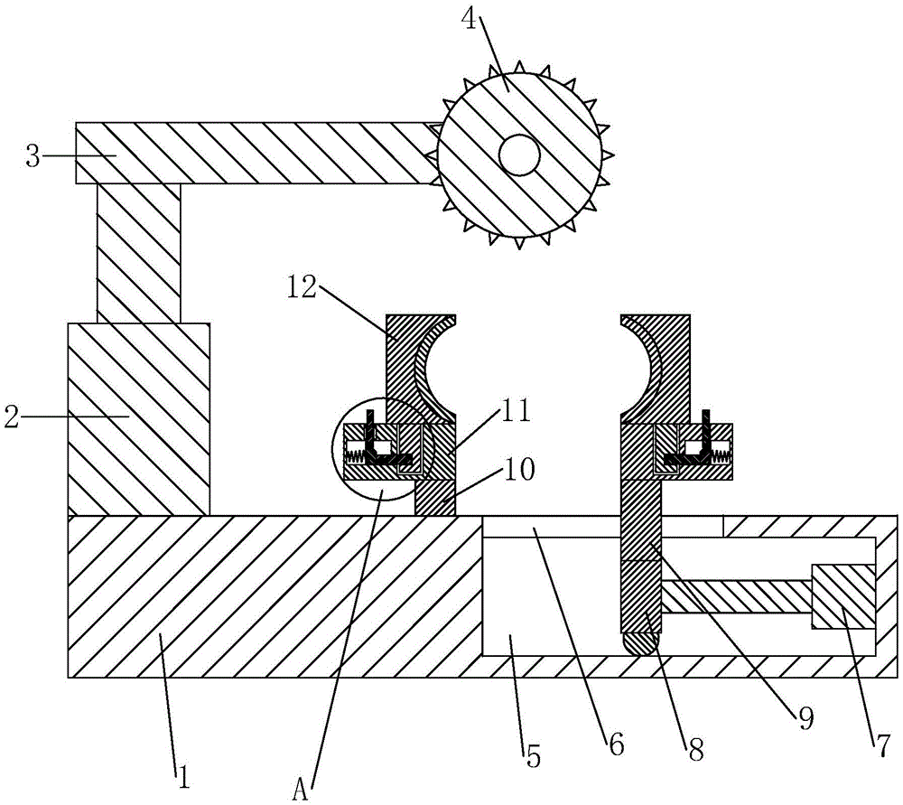
图1为实施例一的剖视图;Fig. 1 is the sectional view of embodiment one;
图2为图1中A处的放大图;Fig. 2 is the enlarged view of place A in Fig. 1;
图3为实施例二中安装块和卡板的剖视图;Fig. 3 is the sectional view of mounting block and clamping plate in embodiment two;
图4为图3中B处的放大图;Fig. 4 is the enlarged view of place B in Fig. 3;
图5为图3中C处的放大图。FIG. 5 is an enlarged view at point C in FIG. 3 .
附图标记:1、底座;2、液压杆;3、支撑板;4、切割电机;5、内腔;6、第一滑槽;7、气缸;8、连杆;9、移动柱;10、固定块;11、安装块;12、卡板;13、插块;14、连接孔;15、插槽;16、空腔;17、通孔;18、插销;19、第一滑孔;20、移动块;21、推杆;22、第一倾斜面;23、第一弹簧;24、第二倾斜面;25、第二滑槽;26、滑块;27、插孔;28、定滑轮;29、滑套;30、第三滑槽;31、第二滑孔;32、滑杆;33、第二弹簧;34、拉绳;35、堵头;36、限位板;37、拉环。Reference signs: 1, base; 2, hydraulic rod; 3, support plate; 4, cutting motor; 5, inner chamber; 6, first chute; 7, cylinder; 8, connecting rod; 9, moving column; 10 1, fixed block; 11, installation block; 12, clamping plate; 13, insert block; 14, connection hole; 15, slot; 16, cavity; 17, through hole; 18, latch; 19, first slide hole; 20, moving block; 21, push rod; 22, first inclined surface; 23, first spring; 24, second inclined surface; 25, second chute; 26, slider; 27, jack; 28, fixed Pulley; 29, sliding sleeve; 30, the third chute; 31, the second slide hole; 32, slide bar; 33, the second spring; 34, stay rope; 35, plug; 36, limit plate; 37, pull ring.
具体实施方式Detailed ways
下面将结合本实用新型实施例中的附图,对本实用新型实施例中的技术方案进行清楚、完整地描述,显然,所描述的实施例仅仅是本实用新型一部分实施例,而不是全部的实施例。基于本实用新型中的实施例,本领域普通技术人员在没有做出创造性劳动前提下所获得的所有其他实施例,都属于本实用新型保护的范围。The technical solutions in the embodiments of the present invention will be clearly and completely described below in conjunction with the accompanying drawings in the embodiments of the present invention. Obviously, the described embodiments are only part of the embodiments of the present invention, not all of them. example. Based on the embodiments of the present utility model, all other embodiments obtained by persons of ordinary skill in the art without making creative efforts belong to the scope of protection of the present utility model.
实施例一:Embodiment one:
一种便于夹紧的管材切割机,如图1和图2所示,包括底座1、液压杆2、支撑板3、切割电机4,底座1的内部开设有内腔5,内腔5的顶端腔壁上开设有两个通向底座1外部的第一滑槽6,内腔5内安装有气缸7,气缸7的活塞杆上固定有与其垂直设置的连杆8,连杆8的顶端前后两侧均固定有移动柱9,两根移动柱9分别对应两个第一滑槽6,移动柱9沿着第一滑槽6滑动且其顶端穿出第一滑槽6,底座1的顶端还固定有两块固定块10,两块固定块10分别对应两根移动柱9。本实用新型要解决的技术问题是授权公告号为CN210305963U的中国专利一种切割质量高的管材切割机中存在的无法便捷地更换第一卡板和第二卡板的问题,因此本实用新型仅针对解决该问题的技术特征做具体描述。上述结构在本实施例中不做具体描述,可参考授权公告号为CN210305963U的中国专利一种切割质量高的管材切割机。A pipe cutting machine that is easy to clamp, as shown in Figures 1 and 2, includes a base 1, a hydraulic rod 2, a
固定块10与移动柱9的顶端均固定有安装块11。安装块11的顶端可拆卸连接有卡板12。Both the fixed
卡板12的底端固定有插块13,插块13上开设有连接孔14。An
安装块11的顶端开设有可供插块13插入的插槽15。安装块11的内部开设有空腔16。空腔16的顶端腔壁上开设有通向底座1外部的第一滑孔19。第一滑孔19的两侧孔壁上均开设有第二滑槽25。空腔16与插槽15之间连通有与连接孔14对应的通孔17。空腔16内滑动连接有插销18,插销18的一端位于空腔16内,插销18的另一端通过通孔17穿入连接孔14内。空腔16内还设置有用于移动插销18移动结构。The top of the mounting
移动结构包括移动块20和推杆21,移动块20滑动连接于空腔16内,移动块20的一侧与插销18固定连接且设置有第一倾斜面22,移动块20的另一侧与空腔16的腔壁之间固定连接有第一弹簧23,推杆21的顶端位于底座1的上方,推杆21的底端通过第一滑孔19穿入空腔16内且设置有与第一倾斜面22相匹配的第二倾斜面24。推杆21上固定有用于插入第二滑槽25且在第二滑槽25内滑动的滑块26。The moving structure includes a moving
工作原理:当需要拆卸卡板12时,向下按压推杆21,推杆21沿着第一滑孔19向下移动。推杆21在上下移动的过程中,滑块26在第二滑槽25内上下滑动,一方面提升推杆21上下移动时的稳定性,另一方面当滑块26与第二滑槽25的槽壁接触时,推杆21无法继续移动,从而防止推杆21从第一滑孔19内脱离。推杆21向下移动后,第二倾斜面24按压在第一倾斜面22上。按压在第一倾斜面22上的力可以分解为横向的力,在该力的作用下移动块20沿着空腔16朝背向插块13的方向滑动。移动块20带动插销18缩回空腔16内,插销18上原本通过通孔17插入连接孔14的一端从连接孔14中抽出,插块13不再被固定在插槽15内,向上移动插块13即可将插块13从插槽15中拔出,从而将卡板12从安装块11上拆下。且此时,第一弹簧23被压缩形成朝向插块13的反弹力。Working principle: when the clamping
同理,当需要安装卡板12时,先按压推杆21使插销18缩回空腔16内,再将插块13插入插槽15内,当插块13完全插入插槽15内后,连接孔14与通孔17的位置对应,最后松开按压在推杆21上力,移动块20在第一弹簧23的反弹力的作用下即可沿着空腔16朝向插块13移动,从而带动插销18重新通过通孔17插入连接孔14中,将插块13固定在插槽15内,从而将卡板12固定安装在安装块11上。In the same way, when the
本实用新型能够快捷方便地更换卡板12。The utility model can quickly and conveniently replace the clamping
实施例二:Embodiment two:
与实施例一的不同之处在于,如图3-图5所示,空腔16的顶端腔壁上不再开设有第一滑孔19,而是开设有通向底座1外部的插孔27,并在插孔27的内孔壁上固定有环形橡胶圈(图中未示出)。移动结构不再包括移动块20和推杆21,而是包括定滑轮28和滑套29。定滑轮28通过销轴转动连接于空腔16的前后两侧腔壁上。滑套29固定于空腔16的底侧腔壁上且位于定滑轮28与通孔17之间。滑套29上靠近通孔17的一端开设有第三滑槽30,第三滑槽30的槽底开设有通向滑套29外部的第二滑孔31。插销18上背离插块13的一端以滑动连接的方式插入第三滑槽30内且固定有滑杆32。滑杆32的外部套设有第二弹簧33,第二弹簧33的一端与插销18固定连接,第二弹簧33的另一端与第三滑槽30的槽底壁固定连接。滑杆32的另一端通过第二滑孔31穿出滑套29且固定有拉绳34,拉绳34的另一端绕过定滑轮28且固定有用于插入插孔27的堵头35。堵头35的顶端穿出插孔27且固定有限位板36。限位板36的顶端固定有拉环37。拉绳34上位于定滑轮28与滑套29之间的部分呈水平状,拉绳34上位于堵头35与定滑轮28之间的部分呈竖直状。The difference from Embodiment 1 is that, as shown in Fig. 3-Fig. 5, the first sliding
工作原理:当需要通过移动结构移动插销18,使插销18缩回空腔16内时,通过拉环37向上拉动限位板36,限位板36带动堵头35向上移动,堵头35从插孔27内拔出。通过堵头35向上拉动拉绳34,通过定滑轮28改变力的方向,拉绳34的另一端横向拉动滑杆32,滑杆32沿着第二滑孔31逐渐从滑套29内被拉出,滑杆32带动插销18的一端沿着第三滑槽30向滑套29内移动,插销18的另一端即可从连接孔14内抽出。且此时,第二弹簧33被压缩形成朝向插块13的反弹力。当需要通过移动结构使插销18重新插入连接孔14中时,工作人员捏紧拉环37但不给拉环37施加限制其移动的力。在第二弹簧33的反弹力的作用下,插销18的一端重新插入连接孔14内,堵头35也重新插入插孔27内,限位板36卡在底座1的顶端,防止堵头35掉入空腔16内。且环形橡胶圈的设置提升了堵头35插入插孔27时的稳定性。Working principle: when it is necessary to move the
在本实用新型的描述中,需要说明的是,术语“上”、“下”、“内”、“外”“顶/底端”等指示的方位或位置关系为基于附图所示的方位或位置关系,仅是为了便于描述本实用新型和简化描述,而不是指示或暗示所指的装置或元件必须具有特定的方位、以特定的方位构造和操作,因此不能理解为对本实用新型的限制。此外,术语“第一”、“第二”仅用于描述目的,而不能理解为指示或暗示相对重要性。In the description of the present utility model, it should be noted that the orientations or positional relationships indicated by the terms "upper", "lower", "inner", "outer" and "top/bottom" are based on the orientations shown in the drawings or positional relationship, are only for the convenience of describing the utility model and simplifying the description, and do not indicate or imply that the device or element referred to must have a specific orientation, be constructed and operated in a specific orientation, and therefore cannot be construed as a limitation of the utility model . In addition, the terms "first" and "second" are used for descriptive purposes only, and should not be understood as indicating or implying relative importance.
在本实用新型的描述中,需要说明的是,除非另有明确的规定和限定,术语“安装”、“设置有”、“套设/接”、“连接”等,应做广义理解,例如“连接”,可以是固定连接,也可以是可拆卸连接,或一体地连接;可以是机械连接,也可以是电连接;可以是直接相连,也可以通过中间媒介间接相连,可以是两个元件内部的连通。对于本领域的普通技术人员而言,可以具体情况理解上述术语在本实用新型中的具体含义。In the description of the present utility model, it should be noted that, unless otherwise clearly stipulated and limited, the terms "installation", "set with", "sleeve/connection", "connection", etc. should be understood in a broad sense, for example "Connection" can be a fixed connection, a detachable connection, or an integral connection; it can be a mechanical connection or an electrical connection; it can be a direct connection or an indirect connection through an intermediary, and it can be two components Internal connectivity. Those of ordinary skill in the art can understand the specific meanings of the above terms in the present utility model in specific situations.
对于本领域技术人员而言,显然本实用新型不限于上述示范性实施例的细节,而且在不背离本实用新型的精神或基本特征的情况下,能够以其他的具体形式实现本实用新型。因此,无论从哪一点来看,均应将实施例看作是示范性的,而且是非限制性的,本实用新型的范围由所附权利要求而不是上述说明限定,因此旨在将落在权利要求的等同要件的含义和范围内的所有变化囊括在本实用新型内。不应将权利要求中的任何附图标记视为限制所涉及的权利要求。It is obvious to those skilled in the art that the present invention is not limited to the details of the above exemplary embodiments, and that the present invention can be implemented in other specific forms without departing from the spirit or essential features of the present invention. Therefore, no matter from all points of view, the embodiments should be regarded as exemplary and non-restrictive, and the scope of the present invention is defined by the appended claims rather than the above description, so it is intended to fall within the scope of the claims All changes within the meaning and range of equivalents of the required elements are included in the present invention. Any reference sign in a claim should not be construed as limiting the claim concerned.
此外,应当理解,虽然本说明书按照实施方式加以描述,但并非每个实施方式仅包含一个独立的技术方案,说明书的这种叙述方式仅仅是为清楚起见,本领域技术人员应当将说明书作为一个整体,各实施例中的技术方案也可以经适当组合,形成本领域技术人员可以理解的其他实施方式。In addition, it should be understood that although this specification is described according to implementation modes, not each implementation mode only includes an independent technical solution, and this description in the specification is only for clarity, and those skilled in the art should take the specification as a whole , the technical solutions in the various embodiments can also be properly combined to form other implementations that can be understood by those skilled in the art.
Claims (6)
Priority Applications (1)
| Application Number | Priority Date | Filing Date | Title |
|---|---|---|---|
| CN202221936035.2U CN219188818U (en) | 2022-07-24 | 2022-07-24 | Pipe cutting machine convenient to clamp |
Applications Claiming Priority (1)
| Application Number | Priority Date | Filing Date | Title |
|---|---|---|---|
| CN202221936035.2U CN219188818U (en) | 2022-07-24 | 2022-07-24 | Pipe cutting machine convenient to clamp |
Publications (1)
| Publication Number | Publication Date |
|---|---|
| CN219188818U true CN219188818U (en) | 2023-06-16 |
Family
ID=86702824
Family Applications (1)
| Application Number | Title | Priority Date | Filing Date |
|---|---|---|---|
| CN202221936035.2U Expired - Fee Related CN219188818U (en) | 2022-07-24 | 2022-07-24 | Pipe cutting machine convenient to clamp |
Country Status (1)
| Country | Link |
|---|---|
| CN (1) | CN219188818U (en) |
Cited By (1)
| Publication number | Priority date | Publication date | Assignee | Title |
|---|---|---|---|---|
| CN117067846A (en) * | 2023-09-20 | 2023-11-17 | 中国重汽集团济南动力有限公司 | A variable installation pitch straight thrust rod assembly |
-
2022
- 2022-07-24 CN CN202221936035.2U patent/CN219188818U/en not_active Expired - Fee Related
Cited By (1)
| Publication number | Priority date | Publication date | Assignee | Title |
|---|---|---|---|---|
| CN117067846A (en) * | 2023-09-20 | 2023-11-17 | 中国重汽集团济南动力有限公司 | A variable installation pitch straight thrust rod assembly |
Similar Documents
| Publication | Publication Date | Title |
|---|---|---|
| CN217740713U (en) | Unmanned aerial vehicle battery location chucking device of plant protection | |
| CN217831476U (en) | Punching equipment capable of quickly replacing punching head | |
| CN110877364A (en) | Perforating device is used in new material processing | |
| CN218799433U (en) | Cutting machine with replaceable cutter head | |
| CN213530812U (en) | Upright drill convenient to change fixing device | |
| CN217454174U (en) | Film die-cutting machine | |
| CN115157370A (en) | Blade replacing device | |
| CN213288356U (en) | Auto-parts stamping die convenient to change drift | |
| CN208220797U (en) | A kind of rotary drilling tool for shield machine | |
| CN220902024U (en) | Lithium battery recycling and dismounting device | |
| CN220883171U (en) | Injection mold insert connection structure | |
| CN220533075U (en) | Auxiliary structure for hydraulic shearing machine | |
| CN217751945U (en) | Pole base forming die | |
| CN222139606U (en) | Cutting machine is used in production of carbon fiber cloth | |
| CN218615634U (en) | Carton forming die | |
| CN217942035U (en) | Quick cutter replacing device for hydraulic cutting machine | |
| CN217272884U (en) | Fixing base for laser marking machine | |
| CN213765014U (en) | Cutter disc replacing mechanism for pipe cutting machine | |
| CN215561767U (en) | Grooving device is maintained on road surface | |
| CN219078669U (en) | Guide device capable of being installed rapidly | |
| CN217915716U (en) | Special manufacturing tool for sealing gasket of flange gate | |
| CN220805632U (en) | Shearing mechanism for workpiece machining | |
| CN214919744U (en) | Efficient continuous stamping die for static contact of circuit breaker | |
| CN222968061U (en) | Quick-dismantling raw ear | |
| CN220095165U (en) | Improved slide plate structure of blanking opening of injection molding machine |
Legal Events
| Date | Code | Title | Description |
|---|---|---|---|
| GR01 | Patent grant | ||
| GR01 | Patent grant | ||
| CF01 | Termination of patent right due to non-payment of annual fee | ||
| CF01 | Termination of patent right due to non-payment of annual fee |
Granted publication date: 20230616 |