CN219184242U - Telescopic saliva suction tube - Google Patents
Telescopic saliva suction tube Download PDFInfo
- Publication number
- CN219184242U CN219184242U CN202320037841.4U CN202320037841U CN219184242U CN 219184242 U CN219184242 U CN 219184242U CN 202320037841 U CN202320037841 U CN 202320037841U CN 219184242 U CN219184242 U CN 219184242U
- Authority
- CN
- China
- Prior art keywords
- tube
- telescopic
- saliva suction
- saliva
- telescopic sub
- Prior art date
- Legal status (The legal status is an assumption and is not a legal conclusion. Google has not performed a legal analysis and makes no representation as to the accuracy of the status listed.)
- Active
Links
- 210000003296 saliva Anatomy 0.000 title claims abstract description 79
- 125000006850 spacer group Chemical group 0.000 claims 4
- 238000000034 method Methods 0.000 abstract description 6
- 230000009286 beneficial effect Effects 0.000 abstract description 3
- 206010052428 Wound Diseases 0.000 description 25
- 208000027418 Wounds and injury Diseases 0.000 description 25
- 210000000214 mouth Anatomy 0.000 description 12
- 210000003128 head Anatomy 0.000 description 11
- 239000008280 blood Substances 0.000 description 5
- 210000004369 blood Anatomy 0.000 description 5
- 230000008859 change Effects 0.000 description 3
- 238000010586 diagram Methods 0.000 description 3
- 230000000694 effects Effects 0.000 description 3
- 239000007787 solid Substances 0.000 description 3
- 206010003497 Asphyxia Diseases 0.000 description 2
- 238000004140 cleaning Methods 0.000 description 2
- 238000005516 engineering process Methods 0.000 description 2
- 239000012530 fluid Substances 0.000 description 2
- 238000011002 quantification Methods 0.000 description 2
- 238000004659 sterilization and disinfection Methods 0.000 description 2
- 230000002411 adverse Effects 0.000 description 1
- 238000004873 anchoring Methods 0.000 description 1
- 208000014674 injury Diseases 0.000 description 1
- 230000001788 irregular Effects 0.000 description 1
- 238000012986 modification Methods 0.000 description 1
- 230000004048 modification Effects 0.000 description 1
- 230000008569 process Effects 0.000 description 1
- 230000009747 swallowing Effects 0.000 description 1
- 230000008733 trauma Effects 0.000 description 1
Images


Landscapes
- External Artificial Organs (AREA)
Abstract
本实用新型提供一种可伸缩式吸唾管,属于医疗器械领域。解决了现有技术中吸唾管缺乏有效的固定方式,且无法对伤口的深度及长度进行量化,不能协助医生评估伤口情况的问题。本实用新型包括吸唾管本体及伸缩管,所述吸唾管本体上套设有固定夹,所述伸缩管与吸唾管本体连接且可伸缩设置,所述伸缩管由数根伸缩子管依次套接而成,相邻所述伸缩子管之间滑动连接,所述吸唾管本体和每根伸缩子管上均设有刻度。本实用新型结构简单,使用方便舒适,通过卡座卡于患者颊部进行固定,便于医生独自完成操作,提高工作效率,且能对患者伤口的深度及长度进行量化,有利于协助医生评估伤口情况。
The utility model provides a retractable saliva suction tube, which belongs to the field of medical instruments. It solves the problem that the saliva suction tube in the prior art lacks an effective fixing method, and cannot quantify the depth and length of the wound, and cannot assist doctors in evaluating the wound condition. The utility model comprises a saliva-absorbing tube body and a telescopic tube. The saliva-suction tube body is covered with a fixing clip. The telescopic tube is connected to the saliva-suction tube body and is telescopically arranged. Sequentially socketed, adjacent telescopic sub-tubes are slidably connected, and scales are provided on the body of the saliva suction tube and each telescopic sub-tube. The utility model has the advantages of simple structure, convenient and comfortable use, fixed on the cheek of the patient through the card seat, which is convenient for the doctor to complete the operation alone, improves the work efficiency, and can quantify the depth and length of the patient's wound, which is beneficial to assist the doctor to evaluate the wound condition .
Description
技术领域technical field
本实用新型属于医疗器械技术领域,涉及一种可伸缩式吸唾管。The utility model belongs to the technical field of medical devices and relates to a retractable saliva suction tube.
背景技术Background technique
在现有的技术中,口腔颌面部外伤伤口大小、深度不一且形状不规则,因此无法统一使用无菌刻度尺测量伤口深度及长度,导致医生在病历书写过程中对伤口深度及长度无法量化,导致病历中对患者伤口情况的判定缺乏有效性。In the existing technology, oral and maxillofacial trauma wounds vary in size, depth and irregular shape, so it is impossible to uniformly use a sterile scale to measure the depth and length of the wound, resulting in doctors being unable to determine the depth and length of the wound in the process of writing medical records. Quantification leads to the lack of effectiveness in judging the patient's wound condition in the medical record.
同时,患者的口腔颌面部伤口大小不一,术中出血量也不同,医生可选择合适的吸唾管清除术区血液以保持视野清晰。且在口腔检查治疗过程中,患者口腔会分泌一定的唾液,在现有的技术中,需由助手在旁使用传统吸唾管吸去患者唾液,以协助医生保持口内视野的清晰和维持患者舒适度。但大部分口腔诊所有部分治疗是由医生单人操作,传统吸唾管缺乏有效的固定装置的情况下,易发生吸唾管滑脱,易导致小器械误吞、窒息等不良事件的发生,不仅不便于医生操作,还降低了医生工作效率,影响患者的体验,不利于提高医疗护理安全质量。At the same time, the size of the oral and maxillofacial wounds of the patients varies, and the amount of blood loss during the operation also varies. The doctor can choose a suitable saliva suction tube to remove the blood in the operation area to maintain a clear view. And during oral examination and treatment, the patient's mouth will secrete a certain amount of saliva. In the existing technology, an assistant needs to use a traditional saliva suction tube to suck the patient's saliva, so as to assist the doctor to maintain a clear view of the mouth and maintain the patient's comfort. Spend. However, part of the treatment in most dental clinics is performed by a single doctor. In the absence of effective fixing devices for the traditional saliva suction tube, it is easy to slip off the saliva suction tube, which can easily lead to accidental swallowing of small instruments, suffocation and other adverse events. Not only It is not convenient for doctors to operate, and it also reduces the work efficiency of doctors, affects the experience of patients, and is not conducive to improving the safety and quality of medical care.
因此,需要一种可伸缩式吸唾管,来解决现有技术中吸唾管缺乏有效的固定方式,且无法对伤口的深度及长度进行量化,不能协助医生评估伤口情况的问题。Therefore, a retractable saliva suction tube is needed to solve the problems in the prior art that the saliva suction tube lacks an effective fixing method, cannot quantify the depth and length of the wound, and cannot assist doctors in evaluating the wound condition.
实用新型内容Utility model content
本实用新型提供一种可伸缩式吸唾管,拟解决现有技术中吸唾管缺乏有效的固定方式,且无法对伤口的深度及长度进行量化,不能协助医生评估伤口情况的问题。The utility model provides a retractable saliva suction tube, which intends to solve the problems in the prior art that the saliva suction tube lacks an effective fixing method, cannot quantify the depth and length of the wound, and cannot assist doctors in evaluating the wound condition.
本实用新型采用的技术方案如下:The technical scheme that the utility model adopts is as follows:
一种可伸缩式吸唾管,包括吸唾管本体及伸缩管,所述吸唾管本体上套设有固定夹,所述伸缩管与吸唾管本体连接且可伸缩设置,所述伸缩管由数根伸缩子管依次套接而成,相邻所述伸缩子管之间滑动连接,所述吸唾管本体和每根伸缩子管上均设有刻度。A retractable saliva suction tube, comprising a saliva suction tube body and a telescopic tube, the saliva suction tube body is covered with a fixing clip, the telescopic tube is connected to the saliva suction tube body and is telescopically arranged, and the telescopic tube It is formed by several telescopic sub-tubes being sequentially socketed, and the adjacent telescopic sub-tubes are slidably connected, and the body of the saliva-absorbing tube and each telescopic sub-tube are provided with scales.
上述技术方案的具体工作原理如下:The specific working principle of the above-mentioned technical scheme is as follows:
在对患者的口腔进行检查时,预估患者口腔颌面部伤口深度及长度,将伸缩子管拉长到需要使用的长度,将吸唾管本体伸入患者的口腔颌面部伤口处,通过刻度量出伤口的深度及长度后进行记录,有利于协助医生评估伤口情况。将远端的伸缩子管伸到伤口处吸取患者伤口处的血液,以保持口腔内部术区视野清晰,并将固定夹滑动到合适位置并卡于患者颊部进行固定,不需要助手在旁协助,方便医生进行操作。患者口腔内积液过多会使患者舒适度降低或被呛咳、窒息等情况发生,同理用相同操作可吸取患者口腔内的唾液,避免了患者需要频繁起身吐出积液,影响医生的治疗,提高了医生的工作效率及医疗护理安全质量。When examining the patient's oral cavity, estimate the depth and length of the patient's oral and maxillofacial wound, stretch the telescopic sub-tube to the required length, and extend the saliva suction tube body into the patient's oral and maxillofacial wound. The scale measures the depth and length of the wound and records it, which is helpful for assisting doctors in evaluating the wound condition. Extend the telescopic sub-tube at the far end to the wound to suck blood from the patient’s wound, so as to maintain a clear view of the surgical area inside the oral cavity, and slide the fixing clip to the appropriate position and fix it on the patient’s cheek without the assistance of an assistant , It is convenient for doctors to operate. Too much fluid in the patient's mouth will reduce the comfort of the patient or cause choking, suffocation, etc. Similarly, the same operation can absorb the saliva in the patient's mouth, avoiding the need for the patient to get up frequently to spit out the fluid, which will affect the doctor's treatment , Improve the work efficiency of doctors and the safety and quality of medical care.
在进一步的技术方案中,所述固定夹包括圆形套管和卡座,所述固定夹通过圆形套管滑动设置在吸唾管本体上,所述卡座连接在圆形套管上。In a further technical solution, the fixing clip includes a circular sleeve and a clip, the fixing clip is slidably arranged on the body of the saliva suction tube through the circular sleeve, and the clip is connected to the circular sleeve.
吸唾管长度进行调节后,卡座通过圆形套管在吸唾管本体上滑动调节位置,方便卡于患者颊部进行固定。After the length of the saliva suction tube is adjusted, the card holder slides on the body of the saliva suction tube through the circular sleeve to adjust the position, so that it is conveniently stuck on the patient's cheek for fixing.
在进一步的技术方案中,所述圆形套管上设置有滑槽,所述卡座上设有与滑槽相配合的滑块,所述卡座通过滑块可拆卸连接在圆形套管的滑槽内。In a further technical solution, a chute is provided on the circular sleeve, a slider matching the chute is provided on the card seat, and the card seat is detachably connected to the circular sleeve through the slider. in the chute.
卡座通过滑块与圆形套管上的滑槽相配合,实现可拆卸连接,方便使用及清洗消毒。The card seat cooperates with the chute on the circular casing through the slider to realize detachable connection, which is convenient for use and cleaning and disinfection.
在进一步的技术方案中,所述滑块的一侧设有限位块,所述限位块的尺寸大于所述滑槽的尺寸。In a further technical solution, a limit block is provided on one side of the slider, and the size of the limit block is larger than that of the sliding groove.
将滑块从滑槽的下端滑入滑槽内,限位块在滑槽的底部,对圆形套管提供支撑,避免使用过程中滑块在滑槽内继续向上移动导致滑出后,吸唾管失去固定效果而掉落。Slide the slider into the chute from the lower end of the chute, and the limit block is at the bottom of the chute to provide support for the circular sleeve, so as to prevent the slider from continuing to move upwards in the chute during use and cause it to slide out. The saliva loses its anchoring effect and falls down.
在进一步的技术方案中,所述卡座包括“C”形卡座和“匚”形卡座。In a further technical solution, the deck includes a "C" shaped deck and a "匚" shaped deck.
可根据患者颊部的厚度,合理选用“C”形卡座和“匚”形卡座中的一个卡于患者脸颊,以便于一侧卡座卡于患者颊部后,用手握住另一侧的卡座,以提高患者的舒适度。According to the thickness of the patient's cheek, one of the "C"-shaped holder and the "匚"-shaped holder can be reasonably selected to be stuck on the patient's cheek, so that after one side of the holder is stuck on the patient's cheek, the other can be held by hand. Side decks for increased patient comfort.
在进一步的技术方案中,所述伸缩子管包括第一伸缩子管和第二伸缩子管,所述第一伸缩子管与第二伸缩子管过盈配合,所述第二伸缩子管与吸唾管本体过盈配合。In a further technical solution, the telescopic sub-tube includes a first telescopic sub-tube and a second telescopic sub-tube, the first telescopic sub-tube is in interference fit with the second telescopic sub-tube, and the second telescopic sub-tube is in contact with the second telescopic sub-tube. The body of the saliva suction tube has an interference fit.
采用过盈配合的方式进行伸缩滑动,调节更加方便,结构也更加简单。The telescopic sliding is carried out in the way of interference fit, the adjustment is more convenient, and the structure is simpler.
在进一步的技术方案中,所述第二伸缩子管前端的内壁上和所述吸唾管本体前端的内壁上分别设有第一凸环和第二凸环,所述第一凸环与第一伸缩子管的外壁紧密贴合,所述第二凸环与第二伸缩子管的外壁紧密贴合。In a further technical solution, a first protruding ring and a second protruding ring are respectively provided on the inner wall of the front end of the second telescopic sub-tube and the inner wall of the front end of the saliva suction tube body, and the first protruding ring and the second protruding ring are The outer wall of a telescopic sub-tube is closely attached, and the second convex ring is closely attached to the outer wall of the second telescopic sub-tube.
通过施力将第一伸缩子管拉出第二伸缩子管,第二伸缩子管的前端内壁上的第一凸环,在拉伸完成后,第一凸环与第一伸缩子管的外壁顶的紧,不会松动而发生长度变化,同理,吸唾管本体与第二伸缩子管,在拉伸完成后,也不会松动而发生长度变化。The first telescopic sub-tube is pulled out of the second telescopic sub-tube by applying force, and the first convex ring on the front end inner wall of the second telescopic sub-tube, after the stretching is completed, the first convex ring and the outer wall of the first telescopic sub-tube The top is tight and will not loosen and change in length. Similarly, the body of the saliva suction tube and the second telescopic tube will not loosen and change in length after stretching is completed.
在进一步的技术方案中,所述第一伸缩子管的末端外侧和所述第二伸缩子管的末端外侧分别设有第一限位环和第二限位环,所述第一限位环的直径大于第一凸环,所述第二限位环的直径大于第二凸环。In a further technical solution, a first limit ring and a second limit ring are respectively provided on the outside of the end of the first telescopic sub-tube and the outside of the end of the second telescopic sub-tube, and the first limit ring The diameter of the second limiting ring is larger than that of the first protruding ring, and the diameter of the second limiting ring is larger than that of the second protruding ring.
将第一伸缩子管拉出第二伸缩子管后,第一限位环与第一凸环相抵,对第一伸缩子管的位置进行限制,避免被拉出。同理,吸唾管本体与第二伸缩子管,在拉伸完成后,也不会被拉出,保障吸唾管正常的使用。After the first telescopic sub-tube is pulled out of the second telescopic sub-tube, the first limiting ring is opposed to the first protruding ring to limit the position of the first telescopic sub-tube to avoid being pulled out. Similarly, the main body of the saliva suction tube and the second telescopic tube will not be pulled out after the stretching is completed, so as to ensure the normal use of the saliva suction tube.
在进一步的技术方案中,所述第一伸缩子管在远离所述吸唾管本体的一端设有球形的吸唾头。In a further technical solution, a spherical saliva suction head is provided at the end of the first telescopic tube away from the main body of the saliva suction tube.
球形的吸唾头能够增加吸唾的范围,提高吸取效果。The spherical saliva suction head can increase the range of saliva suction and improve the suction effect.
在进一步的技术方案中,所述吸唾头的表面设置有数个吸孔,每个所述吸孔和伸缩子管的管腔均相连通。In a further technical solution, several suction holes are provided on the surface of the saliva suction head, and each of the suction holes communicates with the lumen of the telescopic sub-pipe.
吸孔能够过滤患者口腔颌面部伤口组织及大块固体碎屑,防止堵塞。The suction hole can filter the patient's oral and maxillofacial wound tissue and large solid debris to prevent blockage.
综上所述,由于采用了上述技术方案,本实用新型的有益效果是:In summary, due to the adoption of the above technical solution, the beneficial effects of the utility model are:
1、本实用新型结构简单,使用方便,通过固定夹的圆形套管在吸唾管本体上滑动到合适位置,并将卡座卡于患者颊部进行固定,医生可以独自完成操作,不需要助手在旁协助,方便医生进行操作,节约人力资源,提高工作效率。1. The utility model is simple in structure and easy to use. The round sleeve of the fixing clip slides to a suitable position on the body of the saliva suction tube, and the card holder is fixed on the cheek of the patient. The doctor can complete the operation alone without The assistant is on the side to assist, which is convenient for doctors to operate, saves human resources and improves work efficiency.
2、本实用新型通过设置第一伸缩子管和第二伸缩子管,使得吸唾管可以进行伸缩调节长度,方便处理不同深度及不同大小的伤口,且具有刻度,能够对伤口的深度及长度进行量化,有利于协助医生评估伤口情况。2. The utility model sets the first telescopic sub-tube and the second telescopic sub-tube, so that the saliva suction tube can be telescopically adjusted in length, which is convenient for treating wounds of different depths and sizes, and has a scale, which can adjust the depth and length of the wound. Quantification is beneficial to assist doctors in assessing wound conditions.
3、本实用新型的卡座可以根据患者颊部的厚度,合理选用“C”形卡座和“匚”形卡座中的一个卡于患者脸颊,以便于一侧卡座卡于患者颊部后,用手握住另一侧的卡座,以提高患者的舒适度。3. According to the thickness of the cheek of the patient, the deck of the utility model can reasonably select one of the "C" shaped deck and the "匚" shaped deck to be stuck on the patient's cheek, so that one side of the deck can be stuck on the patient's cheek Finally, hold the deck on the other side with your hand for greater patient comfort.
4、本实用新型吸唾头上的吸孔能够有效的过滤患者口腔颌面部伤口组织及大块固体碎屑,防止堵塞。4. The suction hole on the saliva suction head of the utility model can effectively filter the patient's oral and maxillofacial wound tissue and large solid debris to prevent blockage.
附图说明Description of drawings
本实用新型将通过例子并参照附图的方式说明,其中:The utility model will be explained by way of example and with reference to the accompanying drawings, wherein:
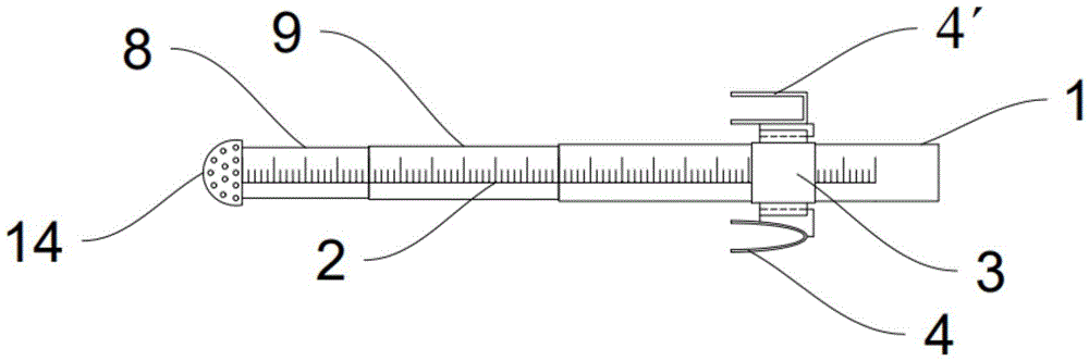
图1是本实用新型的结构示意图;Fig. 1 is the structural representation of the utility model;
图2是本实用新型的管内部结构示意图;Fig. 2 is a schematic diagram of the internal structure of the pipe of the present utility model;
图3是图2中A处的局部放大示意图;Fig. 3 is a partially enlarged schematic diagram of place A in Fig. 2;
图4是图2中B处的局部放大示意图;Fig. 4 is the partially enlarged schematic diagram of place B in Fig. 2;
图5是本实用新型固定夹的结构示意图。Fig. 5 is a schematic structural view of the fixing clip of the present invention.
附图标记:1-吸唾管本体、2-刻度、3-圆形套管、4-“C”形卡座、4′-“匚”形卡座、5-滑槽、6-滑块、7-限位块、8-第一伸缩子管、9-第二伸缩子管、10-第一凸环、11-第二凸环、12-第一限位环、13-第二限位环、14-吸唾头。Reference signs: 1-saliva suction tube body, 2-scale, 3-circular sleeve, 4-"C"-shaped holder, 4'-"匚"-shaped holder, 5-chute, 6-slider , 7-limiting block, 8-first telescopic tube, 9-second telescopic tube, 10-first convex ring, 11-second convex ring, 12-first limiting ring, 13-second limiting Bit ring, 14-saliva suction head.
具体实施方式Detailed ways
为使本申请实施例的目的、技术方案和优点更加清楚,下面将结合本申请实施例中附图,对本申请实施例中的技术方案进行清楚、完整地描述,显然,所描述的实施例仅是本申请一部分实施例,而不是全部的实施例。通常在此处附图中描述和示出的本申请实施例的组件可以各种不同的配置来布置和设计。因此,以下对在附图中提供的本申请的实施例的详细描述并非旨在限制要求保护的本申请的范围,而是仅仅表示本申请的选定实施例。基于本申请的实施例,本领域技术人员在没有做出创造性劳动的前提下所获得的所有其他实施例,都属于本申请保护的范围。In order to make the purpose, technical solutions and advantages of the embodiments of the present application clearer, the technical solutions in the embodiments of the present application will be clearly and completely described below in conjunction with the drawings in the embodiments of the present application. Obviously, the described embodiments are only It is a part of the embodiments of this application, not all of them. The components of the embodiments of the application generally described and illustrated in the figures herein may be arranged and designed in a variety of different configurations. Accordingly, the following detailed description of the embodiments of the application provided in the accompanying drawings is not intended to limit the scope of the claimed application, but merely represents selected embodiments of the application. Based on the embodiments of the present application, all other embodiments obtained by those skilled in the art without making creative efforts belong to the scope of protection of the present application.
在本申请实施例的描述中,需要说明的是,术语“上”、“下”、“左”、“右”、“竖直”、“水平”、“内”、“外”等指示的方位或位置关系为基于附图所示的方位或位置关系,或者是该实用新型产品使用时惯常摆放的方位或位置关系,仅是为了便于描述本申请和简化描述,而不是指示或暗示所指的装置或元件必须具有特定的方位、以特定的方位构造和操作,因此不能理解为对本申请的限制。此外,术语“第一”、“第二”、“第三”等仅用于区分描述,而不能理解为指示或暗示相对重要性。In the description of the embodiments of the present application, it should be noted that the terms "upper", "lower", "left", "right", "vertical", "horizontal", "inner" and "outer" indicate The orientation or positional relationship is based on the orientation or positional relationship shown in the drawings, or the orientation or positional relationship that is usually placed when the utility model product is used, and is only for the convenience of describing the application and simplifying the description, rather than indicating or implying the It should not be construed as limiting the application to indicate that a device or element must have a particular orientation, be constructed, and operate in a particular orientation. In addition, the terms "first", "second", "third", etc. are only used for distinguishing descriptions, and should not be construed as indicating or implying relative importance.
下面结合图1~图5对本实用新型作详细说明。Below in conjunction with Fig. 1~Fig. 5, the utility model is described in detail.
实施例1:Example 1:
本实施例提供一种可伸缩式吸唾管,参阅图1和图2,包括吸唾管本体1及伸缩管,吸唾管本体1上套设有固定夹,伸缩管与吸唾管本体1连接且可伸缩设置,伸缩管由第一伸缩子管8和第二伸缩子管9套接而成,第一伸缩子管8和第二伸缩子管9之间滑动连接,第一伸缩子管8在远离吸唾管本体1的一端设有球形的吸唾头14,吸唾头14的长度为0.5cm,吸唾头14的表面设置有若干个吸孔,每个吸孔和伸缩子管的管腔均相连通,吸唾管本体1、第一伸缩子管8及第二伸缩子管9的外管壁上均设有刻度2,完全拉伸后,第一伸缩子管8、第二伸缩子管9及吸唾管本体1上的刻度2能够连接起来,且长度为10cm,第一伸缩子管8上的刻度2长度为2cm,第二伸缩子管9上的刻度2长度为3cm,吸唾管本体1上的刻度2长度为5cm。This embodiment provides a retractable saliva suction tube, referring to Fig. 1 and Fig. 2, comprising a saliva
在本实施例中,固定夹包括圆形套管3和卡座,圆形套管3与吸唾管本体1过盈配合,固定夹通过圆形套管3在吸唾管本体1上滑动,卡座连接在圆形套管3上。In this embodiment, the fixing clip includes a
在本实施例中,卡座的数量为两个,包括一个“C”形卡座4和一个“匚”形卡座4′,分别固定在圆形套管3的两侧,“C”形卡座4和“匚”形卡座4′的开口朝向患者的颊部使用,具体的卡座的宽度及弧度根据实际使用情况设置。使用时,可根据患者颊部的厚度,合理选用“C”形卡座4和“匚”形卡座4′中的一个卡于患者脸颊,以便于一侧卡座卡于患者颊部后,用手握住另一侧的卡座,以提高患者的舒适度。In this embodiment, there are two decks, including a "C"-shaped
在本实施例中,伸缩子管包括第一伸缩子管8和第二伸缩子管9,其中,第一伸缩子管8与第二伸缩子管9过盈配合,第二伸缩子管9与吸唾管本体1过盈配合,参阅图2-图4,具体是第二伸缩子管9前端的内壁上和吸唾管本体1前端的内壁上分别设有第一凸环10和第二凸环11,第一凸环10与第一伸缩子管8的外壁紧密贴合,第二凸环11与第二伸缩子管9的外壁紧密贴合。In this embodiment, the telescopic sub-tube includes a first
具体的,通过施力将第一伸缩子管8拉出第二伸缩子管9,第二伸缩子管9的前端内壁上的第一凸环10,在拉伸完成后,第一凸环10与第一伸缩子管8的外壁顶的紧,不会松动而发生长度变化,同理,吸唾管本体1与第二伸缩子管9,在拉伸完成后,也不会松动而发生长度变化。Specifically, the first
在本实施例中,参阅图2-图4,第一伸缩子管8的末端外侧和第二伸缩子管9的末端外侧分别设有第一限位环12和第二限位环13,第一限位环12的直径大于第一凸环10,第二限位环13的直径大于第二凸环11。In this embodiment, referring to Fig. 2-Fig. 4, a
具体的,在拉出第一伸缩子管8和第二伸缩子管9时,第一限位环12和第二限位环13分别与第一凸环10和第二凸环11相抵,形成限制,避免被拉出,保障吸唾管正常的使用。Specifically, when the first
上述实施例的具体使用方法如下:The concrete usage method of above-mentioned embodiment is as follows:
医生在对患者的口腔进行检查时,首先预估患者口腔颌面部伤口深度及长度,通过拉出第一伸缩子管8和第二伸缩子管9到需要使用的长度,伸入患者的口腔颌面部伤口内,通过管外侧壁上的刻度2,量出伤口的深度及长度后进行记录。在需要清理患者的伤口处的血液时,将第一伸缩子管8前端的吸唾头14伸至待清理血液处,并通过圆形套管3将卡座滑动到合适的位置并将卡座卡于患者的颊部,即卡座夹在患者的颊部上,卡座的一侧位于患者的口腔内,一侧在口腔外,完成吸唾管的固定,用“C”形卡座4还是“匚”形卡座4′,可根据患者颊部的厚度,合理选用,而吸唾头14上的吸孔能够过滤患者口腔中伤口组织及大块固体碎屑,防止堵塞。同理,吸取患者口腔内的唾液时,将吸唾头14伸至待清理唾液处,并通过卡座卡于患者的颊部,完成吸唾管的固定。固定后,不需要助手在旁协助,能够方便医生进行操作,提高了医生的工作效率及医疗护理安全质量。When the doctor examines the patient's oral cavity, he first estimates the depth and length of the patient's oral and maxillofacial wound, and then stretches the first
实施例2:Example 2:
与实施例1不同的是,在本实施例中,参阅图5,圆形套管3上开设有滑槽5,卡座上设有与滑槽5相配合的滑块6,滑块6的一侧设有限位块7,限位块7的尺寸大于滑槽5的尺寸,卡座通过滑块6可拆卸安装在圆形套管3的滑槽5内。The difference from
具体的,实现了卡座和圆形套管3之间的可拆卸连接,方便使用及清洗消毒,滑块6的形状根据卡座的形状进行设置,保证滑块6和卡座连接的稳定性,使用时,将卡座的滑块6从滑槽5的下端滑入滑槽5内,限位块7在滑槽5的底部,对圆形套管3提供支撑,避免使用过程中滑块6在滑槽5内继续向上移动导致滑出后,吸唾管失去固定效果而掉落的情况发生。Specifically, the detachable connection between the card seat and the
以上所述实施例仅表达了本申请的具体实施方式,其描述较为具体和详细,但并不能因此而理解为对本申请保护范围的限制。应当指出的是,对于本领域的普通技术人员来说,在不脱离本申请技术方案构思的前提下,还可以做出若干变形和改进,这些都属于本申请的保护范围。The above-mentioned embodiments only express the specific implementation manners of the present application, and the descriptions thereof are relatively specific and detailed, but should not be construed as limiting the protection scope of the present application. It should be noted that those skilled in the art can make several modifications and improvements without departing from the concept of the technical solution of the present application, and these all belong to the protection scope of the present application.
Claims (10)
Priority Applications (1)
| Application Number | Priority Date | Filing Date | Title |
|---|---|---|---|
| CN202320037841.4U CN219184242U (en) | 2023-01-06 | 2023-01-06 | Telescopic saliva suction tube |
Applications Claiming Priority (1)
| Application Number | Priority Date | Filing Date | Title |
|---|---|---|---|
| CN202320037841.4U CN219184242U (en) | 2023-01-06 | 2023-01-06 | Telescopic saliva suction tube |
Publications (1)
| Publication Number | Publication Date |
|---|---|
| CN219184242U true CN219184242U (en) | 2023-06-16 |
Family
ID=86710359
Family Applications (1)
| Application Number | Title | Priority Date | Filing Date |
|---|---|---|---|
| CN202320037841.4U Active CN219184242U (en) | 2023-01-06 | 2023-01-06 | Telescopic saliva suction tube |
Country Status (1)
| Country | Link |
|---|---|
| CN (1) | CN219184242U (en) |
Cited By (1)
| Publication number | Priority date | Publication date | Assignee | Title |
|---|---|---|---|---|
| CN121265999A (en) * | 2025-11-24 | 2026-01-06 | 四川省第四人民医院 | Air passage clearance device for assisting swallowing training |
-
2023
- 2023-01-06 CN CN202320037841.4U patent/CN219184242U/en active Active
Cited By (1)
| Publication number | Priority date | Publication date | Assignee | Title |
|---|---|---|---|---|
| CN121265999A (en) * | 2025-11-24 | 2026-01-06 | 四川省第四人民医院 | Air passage clearance device for assisting swallowing training |
Similar Documents
| Publication | Publication Date | Title |
|---|---|---|
| US5071347A (en) | Dental instrument for removing saliva | |
| US20130337405A1 (en) | Multi-lumen aspirator device | |
| CN209996519U (en) | A multifunctional bite pad | |
| CN221770119U (en) | A new type of oral cheek retractor | |
| CN203970596U (en) | opener | |
| CN216318145U (en) | Improvement saliva suction device | |
| CN203842158U (en) | Switchable multifunctional suction tube for oral treatment | |
| CN211325590U (en) | A visual minimally invasive diagnosis and treatment trolley | |
| CN211512121U (en) | Operating forceps with fixing structure | |
| CN217219258U (en) | A multipurpose saliva suction device | |
| CN223350361U (en) | A multifunctional dental saliva suction tube | |
| CN208319605U (en) | Medical negative pressure formula cleaning device | |
| CN111529110A (en) | Negative pressure mouth gag for oral medical treatment and use method | |
| CN211409481U (en) | Oral cleaning tube for bedridden patients | |
| CN203074917U (en) | Cleaning and suction integrated oral nursing device | |
| CN211460179U (en) | An anti-fouling pillow | |
| CN216294315U (en) | Tooth support type oral cavity fixing aspirator | |
| CN206453823U (en) | The special detachable aspiration-type curet group set of scope skull base surgery | |
| CN220608778U (en) | Orthopedics nail crossing flushing fluid collection device | |
| CN204181728U (en) | The clean suit of a kind of mouth care | |
| CN216454913U (en) | An improved saliva-sucking adjustable mouth mirror | |
| CN218075630U (en) | A pacemaker head frame that is easy to adjust | |
| RU223304U1 (en) | BITE BLOCK | |
| CN223994887U (en) | Saliva suction mouth mirror for dentistry | |
| RU219765U1 (en) | Device for oral hygiene of seriously ill patients |
Legal Events
| Date | Code | Title | Description |
|---|---|---|---|
| GR01 | Patent grant | ||
| GR01 | Patent grant |