CN219172511U - Mounting bracket for combined light truck steering oil tank and ECU - Google Patents
Mounting bracket for combined light truck steering oil tank and ECU Download PDFInfo
- Publication number
- CN219172511U CN219172511U CN202223542124.1U CN202223542124U CN219172511U CN 219172511 U CN219172511 U CN 219172511U CN 202223542124 U CN202223542124 U CN 202223542124U CN 219172511 U CN219172511 U CN 219172511U
- Authority
- CN
- China
- Prior art keywords
- bracket
- oil tank
- mounting plate
- mounting
- plate
- Prior art date
- Legal status (The legal status is an assumption and is not a legal conclusion. Google has not performed a legal analysis and makes no representation as to the accuracy of the status listed.)
- Active
Links
Images
Classifications
-
- Y—GENERAL TAGGING OF NEW TECHNOLOGICAL DEVELOPMENTS; GENERAL TAGGING OF CROSS-SECTIONAL TECHNOLOGIES SPANNING OVER SEVERAL SECTIONS OF THE IPC; TECHNICAL SUBJECTS COVERED BY FORMER USPC CROSS-REFERENCE ART COLLECTIONS [XRACs] AND DIGESTS
- Y02—TECHNOLOGIES OR APPLICATIONS FOR MITIGATION OR ADAPTATION AGAINST CLIMATE CHANGE
- Y02T—CLIMATE CHANGE MITIGATION TECHNOLOGIES RELATED TO TRANSPORTATION
- Y02T10/00—Road transport of goods or passengers
- Y02T10/10—Internal combustion engine [ICE] based vehicles
- Y02T10/40—Engine management systems
Landscapes
- Power Steering Mechanism (AREA)
Abstract
本实用新型属于轻卡配件技术领域,具体涉及一种组合轻卡转向油罐与ECU的安装支架,包括支架安装板,支架安装板一侧设置有加强板,支架安装板另一侧设置有油罐安装板,油罐安装板上设置有用于安装转向油罐的第一安装孔,支架安装板上部设置有用于安装ECU的第二安装孔,支架安装板下部设置有第三安装孔。支架安装板上的第三安装孔用于将支架安装板固定在车体上,第二安装孔用于将ECU安装连接到支架安装板上,油罐安装板用于安装转向油罐,转向油罐和ECU集成安装到一起,节省了车架后侧腹面内部安装空间,为车架纵梁节省出更多安装孔。

The utility model belongs to the technical field of light truck accessories, in particular to a mounting bracket for combining a light truck steering oil tank and an ECU, comprising a bracket mounting plate, one side of the bracket mounting plate is provided with a reinforcing plate, and the other side of the bracket mounting plate is provided with an oil tank mounting bracket. The oil tank mounting plate is provided with the first mounting hole for installing the steering oil tank, the upper part of the bracket mounting plate is provided with the second mounting hole for installing the ECU, and the lower part of the bracket mounting plate is provided with the third mounting hole. The third mounting hole on the bracket mounting plate is used to fix the bracket mounting plate on the car body, the second mounting hole is used to install and connect the ECU to the bracket mounting plate, the oil tank mounting plate is used to install the steering oil tank, the steering oil The tank and ECU are integrated and installed together, which saves the internal installation space on the rear side of the frame and saves more installation holes for the frame longitudinal beam.
Description
技术领域technical field
本实用新型涉及轻卡配件技术领域,具体涉及一种组合轻卡转向油罐与ECU的安装支架。The utility model relates to the technical field of light truck accessories, in particular to a mounting bracket for combining a light truck steering oil tank and an ECU.
背景技术Background technique
转向油罐的作用是储存、滤清并冷却液压助力转向系统的工作油液,ECU的作用是随时监控着输入的各种数据和汽车运行的各种状态,例如加速、打滑、油耗等,并按照预先设计的程序计算各种传感器送来的信息,经过处理以后,把各个参数发送给各相关的执行机构,执行各种预定的控制功能。The role of the steering oil tank is to store, filter and cool the working fluid of the hydraulic power steering system. The role of the ECU is to monitor various input data and various states of the car at any time, such as acceleration, skid, fuel consumption, etc., and Calculate the information sent by various sensors according to the pre-designed program, and after processing, send each parameter to each related actuator to execute various predetermined control functions.
轻卡目前安装的转向油罐和发动机ECU采用单独支架分别安装的方式,转向油罐采用独立支架安装在车架左纵梁外侧,驾驶室下方;发动机ECU支架安装在车架左纵梁内侧,车架上翼面以下,此安装方式在专用车应用场景下,会出现改装厂安装时,安装空间不足、与底盘部件物理干涉的情况。The steering oil tank and engine ECU currently installed on light trucks are installed separately with separate brackets. Below the wing surface of the rack, this installation method may cause insufficient installation space and physical interference with chassis components when installed in a refitting factory in the application scenario of a special vehicle.
公开号为CN204161446U,公开日为2015.02.18的中国专利一种轻卡用方形转向油罐支架,公开了支架本体、第一紧固件和第二紧固件;支架本体包括第一支架本体面、第二支架本体面和第三支架本体面;第一支架本体面顶部与第一紧固件固定连接;第一紧固件的横剖面成“几”型,两端均延伸形成安装面,安装面上设有通孔;第二紧固件与所述第一紧固件形状相同,第一紧固件与第二紧固件通过螺栓固定在一起,形成“口”型;第二紧固件位于第一支架本体面与第二支架本体面夹角的内侧。上述专利只能用于安装转向油罐的安装,不能将转向油罐和ECU组合安装起来,浪费了轻卡的空间。The Chinese patent with the publication number CN204161446U and the publication date of 2015.02.18 is a square steering oil tank bracket for light trucks, which discloses the bracket body, the first fastener and the second fastener; the bracket body includes the first bracket body surface, The body surface of the second bracket and the body surface of the third bracket; the top of the body surface of the first bracket is fixedly connected with the first fastener; There are through holes on the surface; the second fastener has the same shape as the first fastener, and the first fastener and the second fastener are fixed together by bolts to form a "mouth" shape; the second fastener The part is located inside the angle between the first bracket body surface and the second bracket body surface. The above-mentioned patents can only be used to install the steering oil tank, and the steering oil tank and ECU cannot be combined and installed, which wastes the space of the light truck.
发明内容Contents of the invention
本实用新型针对上述背景技术中安装支架不能将转向支架和ECU组合安装起来、浪费轻卡空间的问题,提供了一种组合轻卡转向油罐与ECU的安装支架。The utility model aims at the problem that the mounting bracket cannot combine the steering bracket and the ECU in the above background technology, which wastes light truck space, and provides a mounting bracket for combining the light truck steering oil tank and the ECU.
本实用新型未达到以上技术效果采取的技术方案是:一种组合轻卡转向油罐与ECU的安装支架,包括支架安装板,支架安装板一侧设置有加强板,支架安装板另一侧设置有油罐安装板,油罐安装板上设置有用于安装转向油罐的第一安装孔,支架安装板上部设置有用于安装ECU的第二安装孔,支架安装板下部设置有第三安装孔。支架安装板上的第三安装孔用于将支架安装板固定在车体上,第二安装孔用于将ECU安装连接到支架安装板上,油罐安装板用于安装转向油罐,转向油罐和ECU集成安装到一起,节省了车架后侧腹面内部安装空间,为车架纵梁节省出更多安装孔。The technical scheme adopted by the utility model without achieving the above technical effect is: a mounting bracket for combining light truck steering oil tank and ECU, including a bracket mounting plate, a reinforcing plate is arranged on one side of the bracket mounting plate, and a reinforcing plate is arranged on the other side of the bracket mounting plate The oil tank mounting plate is provided with a first mounting hole for installing a steering oil tank, the upper part of the bracket mounting plate is provided with a second mounting hole for installing an ECU, and the lower part of the bracket mounting plate is provided with a third mounting hole. The third mounting hole on the bracket mounting plate is used to fix the bracket mounting plate on the car body, the second mounting hole is used to install and connect the ECU to the bracket mounting plate, the oil tank mounting plate is used to install the steering oil tank, the steering oil The tank and ECU are integrated and installed together, which saves the internal installation space on the rear side of the frame and saves more installation holes for the frame longitudinal beam.
进一步的,支架安装板、加强板和油罐安装板由一块钢板折弯成型,加强板和油罐安装板向支架安装板同一侧弯折。支架安装板、加强板和油罐安装板结构简单,制作简单。Further, the bracket mounting plate, the reinforcing plate and the oil tank mounting plate are formed by bending one steel plate, and the reinforcing plate and the oil tank mounting plate are bent toward the same side of the bracket mounting plate. The bracket mounting plate, the reinforcing plate and the oil tank mounting plate are simple in structure and easy to manufacture.
进一步的,油罐安装板为梯形,第一安装孔设置有两个,两个第一安装孔均设置在油罐安装板的上部。Further, the oil tank installation plate is trapezoidal, and there are two first installation holes, and the two first installation holes are both arranged on the upper part of the oil tank installation plate.
进一步的,油罐安装板面向加强板的一侧设置有加强筋。加强筋可以增加油罐安装板的强度。Further, the side of the oil tank mounting plate facing the reinforcing plate is provided with reinforcing ribs. Ribs can increase the strength of the tank mounting plate.
进一步的,支架安装板的中间下部位置开设有第一凹槽,支架安装板(1)的中间上部位置开设有第二凹槽。第一凹槽和第二凹槽可以减小整体结构质量,保证结构的轻量化,第二凹槽还可以为ECU保护罩预留出安装位置。Further, a first groove is provided at the middle lower part of the bracket mounting plate, and a second groove is provided at the middle upper part of the bracket mounting plate (1). The first groove and the second groove can reduce the weight of the overall structure and ensure the light weight of the structure, and the second groove can also reserve an installation position for the ECU protective cover.
进一步的,第二安装孔设置有四个,四个第二安装孔在支架安装板上左右对称分布,第三安装孔设置有四个,四个第三安装孔在支架安装板上左右对称分布。Further, there are four second mounting holes, and the four second mounting holes are distributed symmetrically left and right on the bracket mounting plate, and there are four third mounting holes, and the four third mounting holes are symmetrically distributed left and right on the bracket mounting plate .
从以上技术方案可以看出本实用新型具有以下有益效果:组合支架可以实现转向油罐和ECU的灵活装配,为底盘布置节省安装空间,提高装配效率,组合支架的通用性强,可以匹配不用宽度的车架。不受车架轴距、宽度的影响,且没有模具费用,节约生产成本。From the above technical solutions, it can be seen that the utility model has the following beneficial effects: the combined bracket can realize the flexible assembly of the steering oil tank and the ECU, save installation space for the chassis layout, improve assembly efficiency, and the combined bracket has strong versatility and can match different widths frame. It is not affected by the wheelbase and width of the frame, and there is no mold cost, which saves production costs.
附图说明Description of drawings
为了更清楚地说明本实用新型的技术方案,下面将对描述中所需要使用的附图作简单地介绍,显而易见地,下面描述中的附图仅仅是本实用新型的一些实施例,对于本领域普通技术人员来讲,在不付出创造性劳动的前提下,还可以根据这些附图获得其他的附图。In order to illustrate the technical solution of the utility model more clearly, the accompanying drawings that need to be used in the description will be briefly introduced below. Obviously, the accompanying drawings in the following description are only some embodiments of the utility model. Ordinary technicians can also obtain other drawings based on these drawings on the premise of not paying creative work.
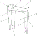
图1为本实用新型具体实施方式的结构示意图。Fig. 1 is a schematic structural view of a specific embodiment of the present invention.
图中:1、支架安装板,2、加强板,3、油罐安装板,4、第一安装孔,5、第二安装孔,6、第三安装孔,7、加强筋,8、第一凹槽,9、第二凹槽。In the figure: 1. Bracket mounting plate, 2. Reinforcing plate, 3. Oil tank mounting plate, 4. First mounting hole, 5. Second mounting hole, 6. Third mounting hole, 7. Reinforcing rib, 8. Second mounting hole One groove, 9, the second groove.
具体实施方式Detailed ways
为使得本实用新型的目的、特征、优点能够更加的明显和易懂,下面将结合本具体实施例中的附图,对本实用新型中的技术方案进行清楚、完整地描述,显然,下面所描述的实施例仅仅是本实用新型一部分实施例,而非全部的实施例。基于本专利中的实施例,本领域普通技术人员在没有做出创造性劳动前提下所获得的所有其它实施例,都属于本专利保护的范围。In order to make the purpose, features and advantages of the present utility model more obvious and understandable, the technical solutions in the present utility model will be clearly and completely described below in conjunction with the accompanying drawings in this specific embodiment. Obviously, the following description The embodiments are only a part of the embodiments of the present utility model, but not all embodiments. Based on the embodiments in this patent, all other embodiments obtained by persons of ordinary skill in the art without creative efforts fall within the protection scope of this patent.
根据图1所示,一种组合轻卡转向油罐与ECU的安装支架,包括支架安装板1,支架安装板1一侧设置有加强板2,支架安装板1另一侧设置有油罐安装板3,油罐安装板3上设置有用于安装转向油罐的第一安装孔4,支架安装板1上部设置有用于安装ECU的第二安装孔5,支架安装板1下部设置有第三安装孔6。As shown in Figure 1, a mounting bracket for a combined light truck steering oil tank and ECU includes a bracket mounting plate 1, a reinforcing plate 2 is provided on one side of the bracket mounting plate 1, and an oil tank mounting plate is provided on the other side of the bracket mounting plate 1 3. The oil
支架安装板1、加强板2和油罐安装板3由一块钢板折弯成型,加强板2和油罐安装板3向支架安装板1同一侧弯折,油罐安装板3为梯形,第一安装孔4设置有两个,两个第一安装孔4均设置在油罐安装板3的上部,油罐安装板3面向加强板2的一侧设置有加强筋7,支架安装板1的中间下部位置开设有第一凹槽8,支架安装板1的中间上部位置开设有第二凹槽9,第二安装孔5设置有四个,四个第二安装孔5在支架安装板1上部左右对称分布,第三安装孔6设置有四个,四个第三安装孔6在支架安装板1下部左右对称分布。The bracket mounting plate 1, the reinforcement plate 2 and the oil
本实用新型的工作原理为:转向油罐通过第一安装孔4安装在油罐安装板3上,ECU通过第二安装孔5安装在支架安装板1上,支架安装板1通过第三安装孔6安装在车体上,安装完成。The working principle of the utility model is: the steering oil tank is installed on the oil
对所公开的实施例的上述说明,使本领域专业技术人员能够实现或使用本实用新型。对这些实施例的多种修改对本领域的专业技术人员来说将是显而易见的,本文中所定义的一般原理可以在不脱离本实用新型的精神或范围的情况下,在其它实施例中实现。因此,本实用新型将不会被限制于本文所示的这些实施例,而是要符合与本文所公开的原理和新颖特点相一致的最宽的范围。The above description of the disclosed embodiments enables those skilled in the art to realize or use the utility model. Various modifications to these embodiments will be readily apparent to those skilled in the art, and the general principles defined herein may be implemented in other embodiments without departing from the spirit or scope of the invention. Therefore, the present invention will not be limited to these embodiments shown herein, but will conform to the widest scope consistent with the principles and novel features disclosed herein.
Claims (6)
Priority Applications (1)
| Application Number | Priority Date | Filing Date | Title |
|---|---|---|---|
| CN202223542124.1U CN219172511U (en) | 2022-12-16 | 2022-12-16 | Mounting bracket for combined light truck steering oil tank and ECU |
Applications Claiming Priority (1)
| Application Number | Priority Date | Filing Date | Title |
|---|---|---|---|
| CN202223542124.1U CN219172511U (en) | 2022-12-16 | 2022-12-16 | Mounting bracket for combined light truck steering oil tank and ECU |
Publications (1)
| Publication Number | Publication Date |
|---|---|
| CN219172511U true CN219172511U (en) | 2023-06-13 |
Family
ID=86665080
Family Applications (1)
| Application Number | Title | Priority Date | Filing Date |
|---|---|---|---|
| CN202223542124.1U Active CN219172511U (en) | 2022-12-16 | 2022-12-16 | Mounting bracket for combined light truck steering oil tank and ECU |
Country Status (1)
| Country | Link |
|---|---|
| CN (1) | CN219172511U (en) |
-
2022
- 2022-12-16 CN CN202223542124.1U patent/CN219172511U/en active Active
Similar Documents
| Publication | Publication Date | Title |
|---|---|---|
| CN210191603U (en) | A front end casting extension beam of a dump truck frame | |
| CN207617806U (en) | A kind of reinforcing plate assembly of side-wall outer-plate | |
| CN111746645A (en) | A lightweight frame front end connecting bracket | |
| CN108945106A (en) | Lightweight structure of a sub-frame | |
| CN208216836U (en) | Fore sub frame | |
| CN203651899U (en) | A front mounting bracket for a vehicle frame | |
| CN209739175U (en) | Reinforcement structure of automobile rear wheel cover | |
| CN207416953U (en) | Auxiliary frame structure | |
| CN212890589U (en) | A magnesium alloy steering support assembly and vehicle | |
| CN221794528U (en) | Mounting structure of unmanned pure electric wide-body dumper high-level sensor | |
| CN207773286U (en) | A kind of 8 × 8 bridge layer chassis specials | |
| CN220615442U (en) | Composite material tail gate inner plate cavity reinforcing structure | |
| CN209126826U (en) | Rear floor structure for electric vehicle and electric vehicle including the same | |
| CN217864389U (en) | Anterior additional strengthening of wheel house, body structure and vehicle in back | |
| CN215944687U (en) | Tractor chassis arrangement structure suitable for long-distance trunk logistics transportation | |
| CN219406114U (en) | Automobile back door skeleton structure | |
| CN202062990U (en) | Mounting support of engine | |
| CN207241830U (en) | A kind of side skirt structure for trailer | |
| CN206926712U (en) | A kind of heavy-duty car lightweight steering gear bracket | |
| CN205930279U (en) | Special all -wheel drive car of large -scale coiled tubing equipment in oil field | |
| CN211167104U (en) | Automobile and automobile A column reinforcing plate assembly | |
| CN205220811U (en) | Preceding end support with clad structure | |
| CN209838512U (en) | Urea tank partial shipment assembly installing support | |
| CN116142321A (en) | A high-performance front wall structure | |
| CN208931441U (en) | A kind of front-end module assembly |
Legal Events
| Date | Code | Title | Description |
|---|---|---|---|
| GR01 | Patent grant | ||
| GR01 | Patent grant |