CN219161037U - Quick condensing equipment of condensate water recovery - Google Patents
Quick condensing equipment of condensate water recovery Download PDFInfo
- Publication number
- CN219161037U CN219161037U CN202320056841.9U CN202320056841U CN219161037U CN 219161037 U CN219161037 U CN 219161037U CN 202320056841 U CN202320056841 U CN 202320056841U CN 219161037 U CN219161037 U CN 219161037U
- Authority
- CN
- China
- Prior art keywords
- heat insulation
- filter
- water recovery
- drain pipe
- condensate water
- Prior art date
- Legal status (The legal status is an assumption and is not a legal conclusion. Google has not performed a legal analysis and makes no representation as to the accuracy of the status listed.)
- Active
Links
Images

Landscapes
- Vaporization, Distillation, Condensation, Sublimation, And Cold Traps (AREA)
Abstract
The utility model discloses a condensed water recovery rapid condensing device, which belongs to the technical field of condensed water recovery and comprises a tank body, wherein an exhaust pipe is arranged at the upper end of the tank body, an air inlet pipe is arranged at one side of the lower end of the tank body, a heat insulation component is arranged on the surface of the air inlet pipe, three groups of supporting legs are arranged at the bottom of the tank body, and a collecting tank is arranged in the middle of the bottom of the tank body; the heat insulation assembly is arranged, so that the outer surface of the air inlet pipe is wrapped by the vacuum heat insulation plate and the aerogel felt, the double heat insulation effect can be achieved, heat dissipation caused by heat convection when condensation water passes through the air inlet pipe is reduced, and a good resource saving effect is achieved.
Description
Technical Field
The utility model belongs to the technical field of condensate water recovery, and particularly relates to a condensate water recovery rapid condensing device.
Background
In industrial production, steam has an inseparable link to almost all businesses as an extremely versatile energy source. A large amount of industrial water and coal-based energy are used to generate steam, the heat of which is used to realize industrial production processes, and condensed water is generated after the steam releases a part of heat energy.
Chinese patent application No. 202121003981.7 discloses a condensing unit for recovering condensed water. The novel water tank comprises a tank body and a plurality of supporting legs arranged at the bottom of the tank body, wherein a water collecting pipe is vertically arranged in the center of the tank body, the upper end of the water collecting pipe is connected to the top of the tank body, the lower end of the water collecting pipe is connected to the bottom of the tank body, a drain hole is formed in the center of the bottom of the tank body in the water collecting pipe, a collecting tank covers the bottom of the tank body outside the drain hole, a drain pipe is arranged at the bottom of the collecting tank, an air inlet pipe communicated with the water collecting pipe is arranged at the lower part of the tank body, and an exhaust pipe communicated with the water collecting pipe is arranged at the top of the tank body. The novel energy-saving ship has the advantages of reasonable structural design, convenience in operation, capability of solving the problem of heating of the ship in winter without arranging a boiler alone, labor cost saving, potential safety hazard caused by using the boiler, full utilization of heat of the ship, energy saving and emission reduction, capability of being used by people after conversion, resource waste avoidance and capability of solving the problems existing in the prior art.
The condensation water of the above-mentioned publication may have dirt inside after condensation, and needs to be treated, and at the same time, there is heat loss when the condensation water of the former device passes through the intake pipe.
Disclosure of Invention
To solve the problems set forth in the background art. The utility model provides a condensate water recovery rapid condensing device which has the characteristics of convenience in filtration and good heat insulation effect.
In order to achieve the above purpose, the present utility model provides the following technical solutions: the utility model provides a quick condensing equipment of condensate water recovery, includes the jar body, jar body upper end is provided with the blast pipe, and jar body lower extreme one side is provided with the intake pipe, and the intake pipe surface is provided with thermal-insulated subassembly, and jar body bottom is provided with three sets of supporting legs, is provided with the collecting vat in the middle of the jar body bottom, and the collecting vat lower extreme is provided with the drain pipe, and the drain pipe lower extreme is provided with filter equipment.
Preferably, the filter component comprises a filter cartridge, an active carbon plate and a filter screen, wherein the lower end of the drain pipe is provided with the filter cartridge, the upper end of the interior of the filter cartridge is provided with the filter screen, and the active carbon plate is arranged below the filter screen.
Preferably, the filter assembly further comprises a sealing gasket and a threaded plate, wherein the threaded plate is correspondingly arranged on the lower end surface of the drain pipe and the inner surface of the upper end of the filter cartridge, and the sealing gasket is arranged between the filter cartridge and the bottom of the drain pipe.
Preferably, a plurality of poking round rods are uniformly arranged on the outer surface of the lower end of the filter cylinder, and the poking round rods are connected with the filter cylinder in an oxygen welding mode.
Preferably, the heat insulation assembly comprises an adhesive layer and a vacuum heat insulation plate, wherein the vacuum heat insulation plate is arranged on the outer surface of the drain pipe, and the adhesive layer is arranged between the vacuum heat insulation plate and the drain pipe.
Preferably, the heat insulation assembly further comprises a rubber layer and an aerogel felt, wherein the aerogel felt is arranged on the surface of the vacuum heat insulation plate, and the rubber layer is arranged on the surface of the aerogel felt.
Compared with the prior art, the utility model has the beneficial effects that:
1. the utility model is provided with the filter assembly, the filter cartridge is arranged at the lower end of the drain pipe, the filter screen and the active carbon plate in the filter cartridge can double-filter and sterilize condensed water after condensation, so that the recovered condensed water is kept clean and sanitary, and the filter cartridge can be conveniently disassembled and cleaned, thereby ensuring good filter effect.
2. The heat insulation assembly is arranged, so that the outer surface of the air inlet pipe is wrapped by the vacuum heat insulation plate and the aerogel felt, the double heat insulation effect can be achieved, heat dissipation caused by heat convection when condensation water passes through the air inlet pipe is reduced, and a good resource saving effect is achieved.
Drawings
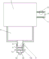
FIG. 1 is a perspective view of the present utility model;
FIG. 2 is a partial cross-sectional view of the present utility model;
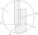
FIG. 3 is an enlarged view of the utility model at A of FIG. 2;
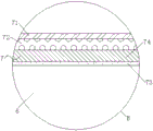
FIG. 4 is an enlarged view of the utility model at B of FIG. 2;
in the figure: 1. an exhaust pipe; 2. a tank body; 3. support legs; 4. a collection tank; 5. a filter assembly; 51. the round rod is poked; 52. a filter cartridge; 53. an activated carbon plate; 54. a filter screen; 55. a sealing gasket; 56. a thread plate; 6. an air inlet pipe; 7. a thermal insulation assembly; 71. a rubber layer; 72. aerogel blanket; 73. an adhesive layer; 74. vacuum insulation panels; 8. and (5) a water drain pipe.
Detailed Description
The following description of the embodiments of the present utility model will be made clearly and completely with reference to the accompanying drawings, in which it is apparent that the embodiments described are only some embodiments of the present utility model, but not all embodiments. All other embodiments, which can be made by those skilled in the art based on the embodiments of the utility model without making any inventive effort, are intended to be within the scope of the utility model.
Example 1
Referring to fig. 1-4, the present utility model provides the following technical solutions: the utility model provides a quick condensing equipment of condensate water recovery, includes a jar body 2, and jar body 2 upper end is provided with blast pipe 1, and jar body 2 lower extreme one side is provided with intake pipe 6, and intake pipe 6 surface is provided with thermal-insulated subassembly 7, and jar body 2 bottom is provided with three group's supporting legs 3, is provided with collecting vat 4 in the middle of the jar body 2 bottom, and collecting vat 4 lower extreme is provided with drain pipe 8, and drain pipe 8 lower extreme is provided with filter component 5.
Specifically, the filter assembly 5 comprises a filter cartridge 52, an active carbon plate 53 and a filter screen 54, wherein the lower end of the drain pipe 8 is provided with the filter cartridge 52, the upper end of the inside of the filter cartridge 52 is provided with the filter screen 54, the active carbon plate 53 is arranged below the filter screen 54,
through adopting above-mentioned technical scheme, filter screen 54 and the active carbon plate 53 in cartridge filter 52 are double filtration and are disinfected to the comdenstion water, get rid of its inside impurity, make water can carry out better recovery.
Specifically, the filter assembly 5 further comprises a sealing pad 55 and a threaded plate 56, wherein the threaded plate 56 is correspondingly arranged on the lower end surface of the drain pipe 8 and the inner surface of the upper end of the filter cartridge 52, the sealing pad 55 is arranged between the filter cartridge 52 and the bottom of the drain pipe 8,
by adopting the above technical scheme, the filter cartridge 52 can be conveniently fixed at the lower end of the drain pipe 8 through the engagement of the screw plate 56, and the sealing gasket 55 can play a sealing effect.
Specifically, the outer surface of the lower end of the filter cartridge 52 is uniformly provided with a plurality of poking round rods 51, the poking round rods 51 are connected with the filter cartridge 52 in an oxygen welding way,
through adopting above-mentioned technical scheme, hold and stir round bar 51, rotation cartridge filter 52 that can be convenient to dismantle the clearance.
When the embodiment is used, the generated condensed water vapor is discharged into the tank body 2 through the air inlet pipe 6 to be subjected to quick heat exchange condensation, the condensed water enters the collecting tank 4 to be discharged through the water discharge pipe 8, the filter cylinder 52 is fixed at the lower end of the water discharge pipe 8 through the engagement of the screw thread plate 56, the sealing gasket 55 has a sealing effect, the filter screen 54 and the activated carbon plate 53 are used for double-filtering and sterilizing the condensed water, impurities in the condensed water are removed, the water can be better recovered, the filter cylinder 52 is used for a long time, the round rod 51 is held, the filter cylinder 52 is rotated conveniently, and therefore disassembly and cleaning are carried out.
Example 2
This embodiment differs from embodiment 1 in that: the heat insulation assembly 7 comprises an adhesive layer 73 and a vacuum heat insulation plate 74, wherein the vacuum heat insulation plate 74 is arranged on the outer surface of the drain pipe 8, the adhesive layer 73 is arranged between the vacuum heat insulation plate 74 and the drain pipe 8,
by adopting the technical scheme, the vacuum insulation board 74 is fixed on the outer surface of the air inlet pipe 6 through the adhesive layer 73, so that a good heat insulation effect can be achieved, and heat loss during condensate flow is reduced.
Specifically, the heat insulation assembly 7 further comprises a rubber layer 71 and an aerogel blanket 72, wherein the aerogel blanket 72 is arranged on the surface of the vacuum heat insulation plate 74, the rubber layer 71 is arranged on the surface of the aerogel blanket 72,
by adopting the above technical scheme, the aerogel blanket 72 can further play a role in heat insulation, and the rubber layer 71 can protect the aerogel blanket 72 so that it is not easily damaged.
When the air intake pipe 6 is used, the vacuum insulation board 74 is fixed on the outer surface of the air intake pipe 6 through the adhesive layer 73, so that a good heat insulation effect can be achieved, heat loss caused by flowing of condensed water is reduced, the aerogel felt 72 can further achieve the heat insulation effect, and the rubber layer 71 can protect the aerogel felt 72, so that the air intake pipe is not easy to damage.
The structure and the working principle of the tank body 2 are disclosed in a condensing device for recovering condensed water disclosed in China patent application No. 202121003981.7, the working principle is that water vapor enters the tank body 2 from an air inlet pipe 6, the water vapor moves in a spiral blade and reacts with a vertical pipe and fins on the surface of the vertical pipe, so that the water vapor is liquefied, becomes water drops, flows into the water collecting pipe through the water collecting pipe and flows into a collecting tank 4, a heat supply mechanism is in serpentine arrangement, more cold water exchanges heat in the tank body 2, the heat exchange effect is improved, and gas in the water vapor is discharged outwards from an exhaust pipe 1.
The working principle and the using flow of the utility model are as follows: when the utility model is used, the generated condensed water vapor is discharged into the tank body 2 through the air inlet pipe 6 for quick heat exchange and condensation, the condensed water enters the collecting tank 4 and is discharged through the water discharge pipe 8, the filter cartridge 52 is fixed at the lower end of the water discharge pipe 8 through the engagement of the screw thread plate 56, the sealing gasket 55 has a sealing effect, the filter screen 54 and the activated carbon plate 53 perform double filtration and sterilization on the condensed water, the impurities in the condensed water are removed, the water can be better recovered, when the filter cartridge 52 is used for a long time, the round rod 51 is held, the filter cartridge 52 can be conveniently rotated, and the disassembly and the cleaning are performed; the vacuum insulation board 74 is fixed on the outer surface of the air inlet pipe 6 through the adhesive layer 73, so that a good heat insulation effect can be achieved, heat loss caused by flowing of condensed water is reduced, the aerogel felt 72 can further achieve the heat insulation effect, and the rubber layer 71 can protect the aerogel felt 72, so that the aerogel felt is not easy to damage.
Although embodiments of the present utility model have been shown and described, it will be understood by those skilled in the art that various changes, modifications, substitutions and alterations can be made therein without departing from the principles and spirit of the utility model, the scope of which is defined in the appended claims and their equivalents.
Claims (6)
1. The utility model provides a quick condensing equipment of condensate water recovery, includes the jar body, its characterized in that: the utility model discloses a jar of jar body, jar body upper end is provided with the blast pipe, jar body lower extreme one side is provided with the intake pipe, and the intake pipe surface is provided with thermal-insulated subassembly, and jar body bottom is provided with three group's supporting legs, is provided with the collecting vat in the middle of the jar body bottom, and the collecting vat lower extreme is provided with the drain pipe, and the drain pipe lower extreme is provided with filtering component.
2. The condensate water recovery rapid condensing device of claim 1, wherein: the filter component comprises a filter cartridge, an active carbon plate and a filter screen, wherein the lower end of the drain pipe is provided with the filter cartridge, the upper end inside the filter cartridge is provided with the filter screen, and the active carbon plate is arranged below the filter screen.
3. The condensate water recovery rapid condensing device of claim 2, wherein: the filter assembly further comprises a sealing gasket and a threaded plate, wherein the threaded plate is correspondingly arranged on the lower end surface of the drain pipe and the inner surface of the upper end of the filter cartridge, and the sealing gasket is arranged between the filter cartridge and the bottom of the drain pipe.
4. The condensate water recovery rapid condensing device of claim 2, wherein: the outer surface of the lower end of the filter cylinder is uniformly provided with a plurality of poking round rods, and the poking round rods are connected with the filter cylinder in an oxygen welding mode.
5. The condensate water recovery rapid condensing device of claim 1, wherein: the heat insulation assembly comprises an adhesive layer and a vacuum heat insulation plate, wherein the vacuum heat insulation plate is arranged on the outer surface of the drain pipe, and the adhesive layer is arranged between the vacuum heat insulation plate and the drain pipe.
6. The condensate water recovery rapid condensing device of claim 5, wherein: the heat insulation assembly further comprises a rubber layer and an aerogel felt, wherein the aerogel felt is arranged on the surface of the vacuum heat insulation plate, and the rubber layer is arranged on the surface of the aerogel felt.
Priority Applications (1)
| Application Number | Priority Date | Filing Date | Title |
|---|---|---|---|
| CN202320056841.9U CN219161037U (en) | 2023-01-09 | 2023-01-09 | Quick condensing equipment of condensate water recovery |
Applications Claiming Priority (1)
| Application Number | Priority Date | Filing Date | Title |
|---|---|---|---|
| CN202320056841.9U CN219161037U (en) | 2023-01-09 | 2023-01-09 | Quick condensing equipment of condensate water recovery |
Publications (1)
| Publication Number | Publication Date |
|---|---|
| CN219161037U true CN219161037U (en) | 2023-06-09 |
Family
ID=86622204
Family Applications (1)
| Application Number | Title | Priority Date | Filing Date |
|---|---|---|---|
| CN202320056841.9U Active CN219161037U (en) | 2023-01-09 | 2023-01-09 | Quick condensing equipment of condensate water recovery |
Country Status (1)
| Country | Link |
|---|---|
| CN (1) | CN219161037U (en) |
-
2023
- 2023-01-09 CN CN202320056841.9U patent/CN219161037U/en active Active
Similar Documents
| Publication | Publication Date | Title |
|---|---|---|
| CN114719620B (en) | Gold smelting furnace flue gas dust treatment device and treatment method | |
| CN212881114U (en) | Decoking device | |
| CN210219836U (en) | High-efficient boiler flue gas recovery heat transfer device convenient to observe and detect | |
| CN218358376U (en) | Waste gas cooling device for feed dryer | |
| CN213790784U (en) | Combined waste gas purifying equipment | |
| CN215162433U (en) | A kind of gas drying purification device | |
| CN208465536U (en) | An air filter for high temperature sewage treatment | |
| CN211536936U (en) | Exhaust-gas treatment cooling device | |
| CN212188452U (en) | Gas collecting device for organic waste gas treatment | |
| WO2023231069A1 (en) | Boiler waste gas treatment equipment | |
| CN223649793U (en) | Online cleaning device for rubber ball condenser | |
| CN223726390U (en) | A waste heat recovery device for waste heat boilers | |
| CN209672357U (en) | Exhaust gas volatile organic compounds by catalytic combustion and non-uniformly distributed heat pipe residual-heat recovery | |
| CN222651965U (en) | A high-efficiency waste heat recovery heat exchanger | |
| CN220345422U (en) | Semiconductor welding fume filtration device | |
| CN218901273U (en) | High-efficient processing apparatus of garbage incinerator tail gas thermal cycle | |
| CN224108229U (en) | A boiler flue gas whitening device | |
| CN221558002U (en) | Efficient zero dryer for processing parts | |
| CN218968913U (en) | Steam cleaning equipment waste water collection structure | |
| CN223500186U (en) | A device for utilizing waste heat from condensate water | |
| CN222631108U (en) | Heat exchange system scale inhibition water treatment equipment | |
| CN223490638U (en) | Safety helmet production waste gas purification device | |
| CN222250108U (en) | Cleaning agent recycling and re-supplying device | |
| CN222799032U (en) | A boiler economizer with gas adsorption function | |
| CN220176530U (en) | A kind of waste gas treatment equipment in metal processing |
Legal Events
| Date | Code | Title | Description |
|---|---|---|---|
| GR01 | Patent grant | ||
| GR01 | Patent grant |