CN219152397U - Polishing equipment for ceramic filter tube processing - Google Patents
Polishing equipment for ceramic filter tube processing Download PDFInfo
- Publication number
- CN219152397U CN219152397U CN202223327652.5U CN202223327652U CN219152397U CN 219152397 U CN219152397 U CN 219152397U CN 202223327652 U CN202223327652 U CN 202223327652U CN 219152397 U CN219152397 U CN 219152397U
- Authority
- CN
- China
- Prior art keywords
- polishing
- fixed
- filter tube
- ceramic filter
- arc plate
- Prior art date
- Legal status (The legal status is an assumption and is not a legal conclusion. Google has not performed a legal analysis and makes no representation as to the accuracy of the status listed.)
- Active
Links
- 238000005498 polishing Methods 0.000 title claims abstract description 89
- 239000000919 ceramic Substances 0.000 title claims abstract description 42
- 239000000428 dust Substances 0.000 claims description 7
- 238000005096 rolling process Methods 0.000 claims description 4
- 238000000034 method Methods 0.000 abstract description 7
- 238000006073 displacement reaction Methods 0.000 abstract description 4
- 238000010586 diagram Methods 0.000 description 2
- 230000000694 effects Effects 0.000 description 2
- 238000012986 modification Methods 0.000 description 2
- 230000004048 modification Effects 0.000 description 2
- 230000009286 beneficial effect Effects 0.000 description 1
- 238000000926 separation method Methods 0.000 description 1
Images
Classifications
-
- Y—GENERAL TAGGING OF NEW TECHNOLOGICAL DEVELOPMENTS; GENERAL TAGGING OF CROSS-SECTIONAL TECHNOLOGIES SPANNING OVER SEVERAL SECTIONS OF THE IPC; TECHNICAL SUBJECTS COVERED BY FORMER USPC CROSS-REFERENCE ART COLLECTIONS [XRACs] AND DIGESTS
- Y02—TECHNOLOGIES OR APPLICATIONS FOR MITIGATION OR ADAPTATION AGAINST CLIMATE CHANGE
- Y02P—CLIMATE CHANGE MITIGATION TECHNOLOGIES IN THE PRODUCTION OR PROCESSING OF GOODS
- Y02P70/00—Climate change mitigation technologies in the production process for final industrial or consumer products
- Y02P70/10—Greenhouse gas [GHG] capture, material saving, heat recovery or other energy efficient measures, e.g. motor control, characterised by manufacturing processes, e.g. for rolling metal or metal working
Landscapes
- Grinding And Polishing Of Tertiary Curved Surfaces And Surfaces With Complex Shapes (AREA)
Abstract
The utility model discloses polishing equipment for ceramic filter tube processing, which comprises a workbench, wherein a supporting base cover is fixed on the upper end surface of the workbench, a polishing motor is movably arranged in the supporting base cover, the tail end of a driving shaft of the polishing motor is fixedly provided with a mounting plate, the side wall of the mounting plate is provided with three polishing plates and three polishing blocks, the side wall of the mounting plate is also fixedly provided with a connecting column, and the outer side wall of the connecting column is fixedly sleeved with a polishing ring; in the using process, the flange head at the tail end of the ceramic filter tube is positioned between the polishing ring and the mounting plate, and the polishing ring and the mounting plate are matched with the displacement of the polishing motor in the X direction in the rotating process to polish the two sides of the flange head of the ceramic filter tube, so that the ceramic filter tube polishing device is convenient to use.
Description
Technical Field
The utility model relates to the technical field of ceramic filter tube processing, in particular to polishing equipment for ceramic filter tube processing.
Background
In the process of processing and producing the ceramic filter tube, the surface of the ceramic filter tube needs to be polished, and the tail end of part of the ceramic filter tube is designed into a flange shape, so that the existing polishing equipment is inconvenient to polish the ceramic filter tube with the flange head due to the specificity of the structural shape; the existing polishing equipment is inconvenient to clamp the ceramic filter tube with a longer length, so that the polishing equipment is inconvenient to match with a polishing motor to polish.
Disclosure of Invention
The utility model aims to solve the problems in the prior art and provides polishing equipment for processing a ceramic filter tube.
In order to achieve the above purpose, the present utility model adopts the following technical scheme:
the utility model provides a pottery filter tube processing is with equipment of polishing, includes the workstation, the up end of workstation is fixed with the supporting base cover, and the supporting base cover internalization is provided with the motor of polishing, and the end of motor drive shaft of polishing is fixed with the mounting disc, is provided with three polishing dish and three polishing piece on the lateral wall of mounting disc, still is fixed with the spliced pole on the lateral wall of mounting disc, fixed cover is equipped with the ring of polishing on the lateral wall of spliced pole.
As a further technical scheme of the utility model, a Y-direction moving plate is movably arranged at the inner bottom of the supporting base cover, two Y-direction guide rails matched with the Y-direction moving plate are symmetrically fixed at the inner bottom of the supporting base cover, and a Y-direction electric push rod is fixed on the side wall of the supporting base cover.
As a further technical scheme of the utility model, the upper end faces of the Y-direction moving plates are symmetrically fixed with two X-direction guide rails, the upper end faces of the two X-direction guide rails are movably provided with the same X-direction moving plate, the upper end faces of the Y-direction moving plates are fixed with X-direction electric push rods, and the polishing motor is fixedly arranged on the upper end faces of the X-direction moving plates.
As a further technical scheme of the utility model, the upper end face of the workbench is fixedly provided with a driving seat, the side wall of the driving seat is rotatably provided with a bearing cylinder cover, one side of the bearing cylinder cover is fixedly provided with a fixed arc plate, the upper end face of the fixed arc plate is rotatably provided with an opening and closing arc plate, and a plurality of opening and closing buckles are arranged between the fixed arc plate and the opening and closing arc plate.
As a further technical scheme of the utility model, the upper end face of the workbench is fixedly provided with a supporting rolling seat which is used by being matched with a fixed arc plate and an opening and closing arc plate, and the upper end face of the workbench is fixedly provided with an electric cabinet.
As a further technical scheme of the utility model, a plurality of interference pieces are fixed on the inner surfaces of the fixed arc plate and the opening and closing arc plate.
As a further technical scheme of the utility model, the upper end face of the supporting base cover is rotatably provided with an opening and closing cover, a dust collector is arranged in the workbench, and an air inlet pipe of the dust collector penetrates into the supporting base cover.
The utility model has the beneficial effects that:
1. after ceramic filter tube with flange head is placed, Y to the flexible end of electric putter shortens, Y to movable plate and motor of polishing are shifted in Y direction, then X to the flexible end extension of electric putter, promote the motor of polishing and be close to ceramic filter tube, then Y to the flexible end extension of electric putter, promote the motor of polishing, the flange head that circle and mounting disc are close to ceramic filter tube of polishing, make the flange head be in between circle and the mounting disc of polishing, make circle and the mounting disc of polishing in the pivoted in-process, cooperate the displacement of the X direction of motor of polishing, polish the both sides of the flange head of ceramic filter tube, convenient to use.
2. Firstly, the opening and closing arc plates are opened, then the ceramic filter tube to be polished is placed in the fixed arc plates, then the opening and closing arc plates are closed, a plurality of opening and closing buckles are buckled, then the bearing cylinder cover rotates together with the fixed arc plates and the opening and closing arc plates, and the polishing operation is carried out by matching with the polishing motor.
Drawings
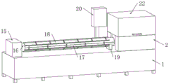
FIG. 1 is a schematic diagram of the overall structure of the present utility model;
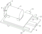
FIG. 2 is a schematic diagram showing the connection of the Y-direction moving plate and the X-direction electric push rod;
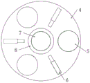
FIG. 3 is a schematic illustration of the attachment of the mounting plate to the sanding plate of the present utility model;
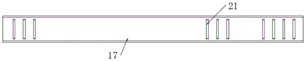
fig. 4 is a schematic view of the internal structure of the fixed arc plate of the present utility model.
In the figure: 1. a work table; 2. a support base cover; 3. polishing a motor; 4. a mounting plate; 5. polishing the grinding disc; 6. polishing the block; 7. a connecting column; 8. polishing the ring; 9. a Y-direction moving plate; 10. a Y-direction guide rail; 11. y-direction electric push rod; 12. an X-direction guide rail; 13. an X-direction moving plate; 14. an X-direction electric push rod; 15. a driving seat; 16. a receiving cylinder cover; 17. fixing the arc plate; 18. an opening and closing arc plate; 19. supporting a rolling seat; 20. an electric control box; 21. a contact piece; 22. the cover is opened and closed.
Detailed Description
In order to further describe the technical means and effects adopted by the present utility model for achieving the intended purpose, the following detailed description will refer to the specific implementation, structure, characteristics and effects according to the present utility model with reference to the accompanying drawings and preferred embodiments.
Referring to fig. 1-4, a polishing device for ceramic filter tube processing comprises a workbench 1, wherein a supporting base cover 2 is fixed on the upper end face of the workbench 1, a polishing motor 3 is movably arranged in the supporting base cover 2, a mounting plate 4 is fixed at the tail end of a driving shaft of the polishing motor 3, three polishing plates 5 and three polishing blocks 6 are arranged on the side wall of the mounting plate 4, a connecting column 7 is further fixed on the side wall of the mounting plate 4, and a polishing ring 8 is fixedly sleeved on the outer side wall of the connecting column 7.
When the ceramic filter tube with the flange head is placed at the designated position, the polishing motor 3 moves correspondingly, the polishing ring 8 and the mounting plate 4 move to the two sides of the flange head, when the driving shaft of the polishing motor 3 drives the mounting plate 4 to rotate, the three polishing plates 5 and the three polishing blocks 6 are driven to rotate together, so that the polishing ring 8 and the mounting plate 4 can polish the right side of the ceramic filter tube with the flange head, and the mounting plate 4 drives the connecting column 7 and the polishing ring 8 to rotate together in the rotating process, so that the polishing ring 8 can polish the left side of the flange head of the ceramic filter tube, and the ceramic filter tube polishing device is convenient to use.
The inner bottom of the supporting base cover 2 is movably provided with a Y-direction moving plate 9, two Y-direction guide rails 10 matched with the Y-direction moving plate 9 are symmetrically fixed on the inner bottom of the supporting base cover 2, a Y-direction electric push rod 11 is fixed on the side wall of the supporting base cover 2, the Y-direction electric push rod 11 is fixedly connected with the bottom of the Y-direction moving plate 9 through a connecting block I, and the telescopic end of the Y-direction electric push rod 11 is shortened and lengthened and used for controlling the Y-direction moving plate 9 and the polishing motor 3 to move in the Y direction.
Two X-direction guide rails 12 are symmetrically fixed on the upper end face of the Y-direction moving plate 9, the same X-direction moving plate 13 is movably arranged on the upper end faces of the two X-direction guide rails 12, an X-direction electric push rod 14 is fixed on the upper end face of the Y-direction moving plate 9, the polishing motor 3 is fixedly arranged on the upper end face of the X-direction moving plate 13, and the telescopic end of the X-direction electric push rod 14 is fixedly connected with the bottom of the X-direction moving plate 13 through a connecting block II.
After the ceramic filter tube with the flange head is placed, the telescopic end of the Y-direction electric push rod 11 is shortened, the Y-direction moving plate 9 and the polishing motor 3 are displaced in the Y direction, then the X-direction electric push rod 14 is extended, the polishing motor 3 is pushed to be close to the ceramic filter tube, then the Y-direction electric push rod 11 is extended, the polishing motor 3, the polishing ring 8 and the mounting plate 4 are pushed to be close to the flange head of the ceramic filter tube, the flange head is positioned between the polishing ring 8 and the mounting plate 4, the polishing ring 8 and the mounting plate 4 are matched with the X-direction displacement of the polishing motor 3 in the rotating process, and polishing operation is carried out on the tail end of the ceramic filter tube.
The up end of workstation 1 is fixed with drive seat 15, rotates on the lateral wall of drive seat 15 to be provided with and accepts drum cover 16, is provided with the drive in the drive seat 15 and accepts drum cover 16 pivoted drive box, accepts one side of drum cover 16 and is fixed with fixed arc 17, and the up end rotation of fixed arc 17 is provided with the arc 18 that opens and shuts, is provided with a plurality of knot that open and shut between fixed arc 17 and the arc 18, and it is prior art to open and shut to detain, and it is not to be described here in detail.
Firstly, the opening and closing arc plate 18 is opened, then the ceramic filter tube to be polished is placed in the fixed arc plate 17, then the opening and closing arc plate 18 is closed, a plurality of opening and closing buckles are buckled, then the carrying cylinder cover 16 rotates together with the fixed arc plate 17 and the opening and closing arc plate 18, and polishing operation is carried out in cooperation with the polishing motor 3.
The upper end surface of the workbench 1 is fixedly provided with a supporting rolling seat 19 which is matched with the fixed arc plate 17 and the opening and closing arc plate 18, and the upper end surface of the workbench 1 is fixedly provided with an electric cabinet 20 for controlling the rotation of the bearing cylinder cover 16.
The inner surfaces of the fixed arc plate 17 and the opening and closing arc plate 18 are respectively fixed with a plurality of abutting pieces 21, so that the fixed arc plate 17 and the opening and closing arc plate 18 can clamp the ceramic filter tube more firmly.
The up end rotation that supports the base cover 2 is provided with the cover that opens and shuts 22, is provided with the dust catcher in the workstation 1, and the intake pipe of dust catcher runs through to in the support base cover 2, through the cooperation of the cover that opens and shuts 22 and the support base cover 2 that sets up, covers the piece that grinds and establishes the separation stop, when polishing operation, the dust catcher work, will support the base cover 2 and open and shut through the intake pipe and cover the piece that polishes in 22 and inhale away, convenient to use.
When the ceramic filter tube polishing machine is used, firstly, the opening and closing arc plate 18 is opened, then a ceramic filter tube to be polished is placed in the fixed arc plate 17, then the opening and closing arc plate 18 is closed, a plurality of opening and closing buckles are buckled, then the bearing cylinder cover 16 rotates together with the fixed arc plate 17 and the opening and closing arc plate 18, and polishing operation is carried out by matching with the polishing motor 3;
after the ceramic filter tube with the flange head is placed, the telescopic end of the Y-direction electric push rod 11 is shortened, the Y-direction moving plate 9 and the polishing motor 3 are displaced in the Y direction, then the X-direction electric push rod 14 is extended, the polishing motor 3 is pushed to be close to the ceramic filter tube, then the Y-direction electric push rod 11 is extended, the polishing motor 3, the polishing ring 8 and the mounting plate 4 are pushed to be close to the flange head of the ceramic filter tube, the flange head is positioned between the polishing ring 8 and the mounting plate 4, the polishing ring 8 and the mounting plate 4 are matched with the X-direction displacement of the polishing motor 3 in the rotating process, and polishing operation is carried out on the tail end of the ceramic filter tube.
The present utility model is not limited to the above embodiments, but is capable of modification and variation in detail, and other modifications and variations can be made by those skilled in the art without departing from the scope of the present utility model.
Claims (7)
1. The utility model provides a pottery filter tube processing is with equipment of polishing, includes workstation (1), its characterized in that, the up end of workstation (1) is fixed with support base cover (2), and support base cover (2) internalization is provided with motor (3) of polishing, and the end of motor (3) drive shaft of polishing is fixed with mounting plate (4), is provided with three polishing dish (5) and three polishing piece (6) on the lateral wall of mounting plate (4), still is fixed with spliced pole (7) on the lateral wall of mounting plate (4), and fixed cover is equipped with on the lateral wall of spliced pole (7) and polishes circle (8).
2. The polishing device for ceramic filter tube processing according to claim 1, wherein a Y-direction moving plate (9) is movably arranged at the inner bottom of the supporting base cover (2), two Y-direction guide rails (10) matched with the Y-direction moving plate (9) are symmetrically fixed at the inner bottom of the supporting base cover (2), and a Y-direction electric push rod (11) is fixed on the side wall of the supporting base cover (2).
3. The polishing device for ceramic filter tube processing according to claim 2, wherein two X-direction guide rails (12) are symmetrically fixed on the upper end surface of the Y-direction moving plate (9), the same X-direction moving plate (13) is movably arranged on the upper end surfaces of the two X-direction guide rails (12), an X-direction electric push rod (14) is fixed on the upper end surface of the Y-direction moving plate (9), and the polishing motor (3) is fixedly arranged on the upper end surface of the X-direction moving plate (13).
4. The polishing device for ceramic filter tube processing according to claim 1, wherein a driving seat (15) is fixed on the upper end face of the workbench (1), a receiving cylinder cover (16) is rotatably arranged on the side wall of the driving seat (15), a fixed arc plate (17) is fixed on one side of the receiving cylinder cover (16), an opening and closing arc plate (18) is rotatably arranged on the upper end face of the fixed arc plate (17), and a plurality of opening and closing buckles are arranged between the fixed arc plate (17) and the opening and closing arc plate (18).
5. The polishing device for ceramic filter tube processing according to claim 4, wherein the upper end surface of the workbench (1) is fixedly provided with a supporting rolling seat (19) used in cooperation with a fixed arc plate (17) and an opening and closing arc plate (18), and the upper end surface of the workbench (1) is fixedly provided with an electric cabinet (20).
6. The polishing equipment for ceramic filter tube processing according to claim 4, wherein a plurality of abutting pieces (21) are fixed on the inner surfaces of the fixed arc plate (17) and the opening and closing arc plate (18).
7. The polishing equipment for ceramic filter tube processing according to claim 1, wherein an opening and closing cover (22) is rotatably arranged on the upper end surface of the supporting base cover (2), a dust collector is arranged in the workbench (1), and an air inlet pipe of the dust collector penetrates into the supporting base cover (2).
Priority Applications (1)
| Application Number | Priority Date | Filing Date | Title |
|---|---|---|---|
| CN202223327652.5U CN219152397U (en) | 2023-04-13 | 2023-04-13 | Polishing equipment for ceramic filter tube processing |
Applications Claiming Priority (1)
| Application Number | Priority Date | Filing Date | Title |
|---|---|---|---|
| CN202223327652.5U CN219152397U (en) | 2023-04-13 | 2023-04-13 | Polishing equipment for ceramic filter tube processing |
Publications (1)
| Publication Number | Publication Date |
|---|---|
| CN219152397U true CN219152397U (en) | 2023-06-09 |
Family
ID=86622124
Family Applications (1)
| Application Number | Title | Priority Date | Filing Date |
|---|---|---|---|
| CN202223327652.5U Active CN219152397U (en) | 2023-04-13 | 2023-04-13 | Polishing equipment for ceramic filter tube processing |
Country Status (1)
| Country | Link |
|---|---|
| CN (1) | CN219152397U (en) |
-
2023
- 2023-04-13 CN CN202223327652.5U patent/CN219152397U/en active Active
Similar Documents
| Publication | Publication Date | Title |
|---|---|---|
| CN210281683U (en) | Bearing ring end face grinding device | |
| CN112497003B (en) | Machining polishing device facilitating part fixing and using method thereof | |
| CN219152369U (en) | Grinding machine | |
| CN219074608U (en) | Mirror spark machine with good workpiece clamping effect | |
| CN112548726A (en) | Glass mirror surface treatment device | |
| CN221270769U (en) | Automobile spare and accessory part processing and polishing equipment | |
| CN109277926A (en) | A kind of mould steel processing derusting device | |
| CN221020242U (en) | Mold closing line polishing device | |
| CN209223790U (en) | A kind of mould steel processing derusting device | |
| CN219234758U (en) | Novel bearing processing equipment | |
| CN219945695U (en) | Polishing machine with workpiece rotation supporting function | |
| CN115319614B (en) | Automatic grinding device of single crystal furnace heater | |
| CN213319209U (en) | Precision surface grinding machine for producing precision die parts | |
| CN212471044U (en) | Polishing machine | |
| CN213765126U (en) | Quick polisher of pipe for machine-building | |
| CN212683522U (en) | Burnishing device for machining | |
| CN209239700U (en) | A kind of device facilitating removal glass burr | |
| CN209734205U (en) | False tooth lingual inner grinding machine | |
| CN220575548U (en) | Epoxy insulation board polishing machine | |
| CN221560767U (en) | Automatic peeling device | |
| CN221696366U (en) | Polishing device convenient to location and used for manufacturing electromechanical equipment | |
| CN221658777U (en) | Bearing bush width processing device | |
| CN221560870U (en) | Surface polishing machine for arc piece processing | |
| CN220881778U (en) | Needle grinding machine convenient to altitude mixture control | |
| CN222095616U (en) | Deburring device |
Legal Events
| Date | Code | Title | Description |
|---|---|---|---|
| GR01 | Patent grant | ||
| GR01 | Patent grant |