CN219131378U - Single hydraulic prop maintenance dismounting device - Google Patents
Single hydraulic prop maintenance dismounting device Download PDFInfo
- Publication number
- CN219131378U CN219131378U CN202320273205.1U CN202320273205U CN219131378U CN 219131378 U CN219131378 U CN 219131378U CN 202320273205 U CN202320273205 U CN 202320273205U CN 219131378 U CN219131378 U CN 219131378U
- Authority
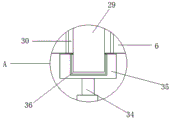
- CN
- China
- Prior art keywords
- wall
- hydraulic prop
- maintenance
- single hydraulic
- groove
- Prior art date
- Legal status (The legal status is an assumption and is not a legal conclusion. Google has not performed a legal analysis and makes no representation as to the accuracy of the status listed.)
- Active
Links
- 238000012423 maintenance Methods 0.000 title claims abstract description 57
- 210000005056 cell body Anatomy 0.000 claims 2
- 238000009434 installation Methods 0.000 abstract description 14
- 238000000034 method Methods 0.000 abstract description 2
- 239000002699 waste material Substances 0.000 description 11
- 238000005299 abrasion Methods 0.000 description 2
- 239000000725 suspension Substances 0.000 description 2
- 230000009286 beneficial effect Effects 0.000 description 1
- 238000010586 diagram Methods 0.000 description 1
- 239000011152 fibreglass Substances 0.000 description 1
- 238000002347 injection Methods 0.000 description 1
- 239000007924 injection Substances 0.000 description 1
- 230000007774 longterm Effects 0.000 description 1
- 239000000243 solution Substances 0.000 description 1
Images
Landscapes
- Manufacture Of Motors, Generators (AREA)
Abstract
The utility model discloses single hydraulic prop maintenance and disassembly equipment which comprises a maintenance and disassembly device, a first installation groove, a second installation groove, an extension rod, an electromagnet and a collecting box, wherein the first installation groove is arranged on the inner wall of the maintenance and disassembly device, a grid mesh is arranged at the output end of a first electric telescopic rod, a sleeve is arranged on the inner wall of a second installation groove, the extension rod is arranged on the outer wall of a limiting block, the electromagnet is arranged on the inner wall of a fixing groove, and the collecting box is arranged on the outer wall of a rod body. According to the utility model, the scrap collecting device is arranged, part of scraps directly fall into the collecting box through the grid net, part of scraps are accumulated on the grid net, the first electric telescopic rod works to drive the grid net to move, so that the extension rod moves in the sleeve to drive the grid net to shake back and forth, the scraps accumulated on the grid net are further shaken into the collecting box, the electromagnet is powered off, and the collecting box is pulled to process the scraps in the collecting box, so that a worker can conveniently collect the scraps in the maintenance and disassembly device.
Description
Technical Field
The utility model relates to the technical field of maintenance and disassembly equipment, in particular to single hydraulic prop maintenance and disassembly equipment.
Background
The single hydraulic prop refers to a single collapsible prop that utilizes hydraulic pressure to create a working resistance and achieve lifting and unloading. The single hydraulic prop is mainly divided into a suspension type single hydraulic prop, a double telescopic suspension type single hydraulic prop, a DN internal injection type single hydraulic prop and a glass fiber reinforced plastic single hydraulic prop, and when the single hydraulic prop is maintained, disassembly equipment is needed to disassemble and maintain the single hydraulic prop.
The existing disassembly and maintenance device can disassemble the single hydraulic prop, but the outer surface of the single hydraulic prop after use needs to be maintained to adsorb a large amount of scraps, and the scraps fall into the maintenance and disassembly equipment, so that workers cannot conveniently clean the scraps.
Disclosure of Invention
The utility model aims to provide single hydraulic prop maintenance and disassembly equipment, which aims to solve the technical problem that the waste scraps in the maintenance and disassembly equipment are convenient to collect and clean.
In order to achieve the above purpose, the present utility model provides the following technical solutions: a single hydraulic prop repair disassembly apparatus comprising:
the outer wall of the maintenance dismounting device is provided with a circuit box;
the installation groove, the installation groove sets up in maintenance dismounting device's inner wall, the electric telescopic handle is installed to the inner wall of installation groove, the grid net is installed to the output of electric telescopic handle, maintenance dismounting device's inner wall is equipped with No. two installation grooves, the sleeve is installed to No. two installation groove's inner wall, telescopic inner wall movable mounting has the stopper, the extension rod is installed to the outer wall of stopper, and the one end of extension rod extends to the outer wall of grid net, maintenance dismounting device's inner wall is equipped with the fixed slot, the electro-magnet is installed to the inner wall of fixed slot, the outer wall movable mounting of electro-magnet has the magnet body, the body of rod is installed to the outer wall of magnet body, the collecting box is installed to the outer wall of body of rod, maintenance dismounting device's inner wall is equipped with the passageway, and the collecting box is located the inside of passageway.
Preferably, the motor is installed at maintenance dismounting device's top, the dismantlement piece is installed to the output of motor, the threaded rod of No. one is installed to the outer wall of dismantlement piece.
Preferably, the mounting panel is installed at maintenance dismounting device's top, a grip block is installed to the outer wall of mounting panel, the outer wall of a grip block is equipped with a hemisphere groove, the hinge is installed to the outer wall of a grip block, no. two grip blocks are installed to the outer wall of hinge, no. two grip blocks's outer wall is equipped with No. two hemisphere grooves, no. two threaded rods are installed to No. two grip blocks's outer wall, no. one grip blocks's outer wall is equipped with a thread groove, and No. two threaded rods's one end extends to the inside of a thread groove, control panel is installed at the top of circuit box.
Preferably, two groups of groove bodies are arranged at the bottom of the first clamping plate, the fixing screw is installed on the inner wall of the groove body, and the sliding groove is formed in the inner wall of the mounting plate.
Preferably, two groups of box bodies are arranged at the bottom of the mounting plate, and motors are arranged on the inner walls of the box bodies.
Preferably, a rotating plate is arranged at the output end of the motor, and a second electric telescopic rod is arranged on the outer wall of the rotating plate.
Preferably, the concave plate is installed at the output end of the second electric telescopic rod, and a second thread groove is formed in the outer wall of the concave plate.
Compared with the prior art, the utility model has the beneficial effects that:
1. according to the utility model, the waste scrap collecting device is arranged, a large amount of waste scraps are adsorbed on the outer surface of the single hydraulic prop after the single hydraulic prop is used, so that the waste scraps fall into the maintenance and disassembly device and are inconvenient for workers to clean the waste scraps, therefore, the waste scraps in the maintenance and disassembly device need to be collected and cleaned, part of waste scraps directly fall into the collection box through the grid net, and part of waste scraps are accumulated on the grid net, the grid net is driven to move by the first electric telescopic rod to enable the extension rod to move, the limiting block is further moved in the sleeve to drive the grid net to shake back and forth, the waste scraps accumulated on the grid net are further rocked into the collection box, the electromagnet is powered off, the collection box is pulled, the magnet body and the rod body are further moved out of the fixing groove, the collection box is further moved out of the channel, and the collected waste scraps in the collection box are processed, so that workers can conveniently collect the waste scraps in the maintenance and disassembly device;
2. according to the utility model, the dismounting and replacing device is arranged, the single hydraulic prop is worn by the first clamping plate and the second clamping plate for a long time, so that the single hydraulic prop is convenient to dismount and replace due to shaking caused by abrasion in the first hemispherical groove and the second hemispherical groove, the first clamping plate needs to be conveniently replaced, the motor rotates to drive the rotating plate to rotate, the rotating plate rotates to drive the second electric telescopic rod to rotate, the second electric telescopic rod works to drive the concave plate to move, the fixing screw is further moved out of the second threaded groove, the concave plate is taken out of the fixing screw, and the first clamping plate is pulled to be dismounted and replaced from the mounting plate, so that the dismounting and replacing of the single hydraulic prop is conveniently prevented from being influenced due to abrasion caused by long-time clamping of the first clamping plate and the second clamping plate.
Drawings
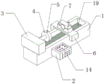
FIG. 1 is a schematic diagram of the overall structure of the present utility model;
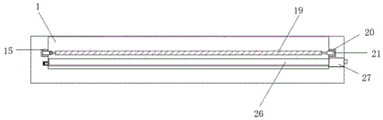
FIG. 2 is a schematic view of the scrap collecting apparatus of the present utility model;
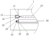
FIG. 3 is a schematic view of a part of the structure of the scrap collecting device of the utility model;
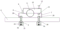
FIG. 4 is a schematic view of a part of the structure of the dismounting and replacing device of the utility model;
FIG. 5 is a schematic view of a portion of a concave plate according to the present utility model.
In the figure: 1. maintaining and disassembling the device; 2. a circuit box; 3. a motor; 4. disassembling the block; 5. a first threaded rod; 6. a mounting plate; 7. a first clamping plate; 8. a first hemispherical groove; 9. a hinge; 10. a second clamping plate; 11. a second hemispherical groove; 12. a second threaded rod; 13. a first thread groove; 14. a control panel; 15. a second mounting groove; 16. a sleeve; 17. a limiting block; 18. an extension rod; 19. a grid mesh; 20. a first mounting groove; 21. a first electric telescopic rod; 22. a fixing groove; 23. an electromagnet; 24. a magnet body; 25. a rod body; 26. a collection box; 27. a channel; 28. a tank body; 29. a fixed screw; 30. a chute; 31. a case body; 32. a motor; 33. a rotating plate; 34. a second electric telescopic rod; 35. a concave plate; 36. and a second thread groove.
Detailed Description
The following description of the embodiments of the present utility model will be made clearly and completely with reference to the accompanying drawings, in which it is apparent that the embodiments described are only some embodiments of the present utility model, but not all embodiments. All other embodiments, which can be made by those skilled in the art based on the embodiments of the utility model without making any inventive effort, are intended to be within the scope of the utility model.
In the description of the present utility model, it should be noted that the directions or positional relationships indicated by the terms "upper", "lower", "inner", "outer", "front", "rear", "both ends", "one end", "the other end", etc. are based on the directions or positional relationships shown in the drawings, are merely for convenience of describing the present utility model and simplifying the description, and do not indicate or imply that the devices or elements referred to must have a specific direction, be configured and operated in the specific direction, and thus should not be construed as limiting the present utility model. Furthermore, the terms "first," "second," and the like, are used for descriptive purposes only and are not to be construed as indicating or implying relative importance.
In the description of the present utility model, it should be noted that, unless explicitly specified and limited otherwise, the terms "mounted," "provided," "connected," and the like are to be construed broadly, and may be fixedly connected, detachably connected, or integrally connected, for example; can be mechanically or electrically connected; can be directly connected or indirectly connected through an intermediate medium, and can be communication between two elements. The specific meaning of the above terms in the present utility model will be understood in specific cases by those of ordinary skill in the art.
Referring to fig. 1 and 4, a single hydraulic prop maintenance and disassembly apparatus includes a maintenance and disassembly device 1, and a circuit box 2 is installed on an outer wall of the maintenance and disassembly device 1. The motor 3 is arranged at the top of the maintenance dismounting device 1, the dismounting block 4 is arranged at the output end of the motor 3, the first threaded rod 5 is arranged on the outer wall of the dismounting block 4, the mounting plate 6 is arranged at the top of the maintenance dismounting device 1, the first clamping plate 7 is arranged on the outer wall of the mounting plate 6, the first hemispherical groove 8 is arranged on the outer wall of the first clamping plate 7, the hinge 9 is arranged on the outer wall of the hinge 9, the second clamping plate 10 is arranged on the outer wall of the second clamping plate 10, the second threaded rod 12 is arranged on the outer wall of the second clamping plate 10, the first threaded groove 13 is arranged on the outer wall of the first clamping plate 7, one end of the second threaded rod 12 extends to the inside of the first threaded groove 13, the control panel 14 is arranged at the top of the circuit box 2, the maintenance dismounting device 1 is a single hydraulic prop maintenance dismounting device, the circuit box 2 is connected with the maintenance dismounting device 1, the control panel 14 controls the circuit box 2 to work, after the base of single hydraulic prop is put into the dismounting block 4, the dismounting block 4 is fixed with the single hydraulic prop through the threaded rod 5, and the single hydraulic prop is located in the hemispherical groove 8 on the clamping plate 7, the clamping plate 10 is rotated through the hinge 9, the hemispherical groove 11 is located outside the single hydraulic prop, the threaded rod 12 is fixed in the threaded groove 13, the single hydraulic prop is fixed on the mounting plate 6, the motor 3 rotates to drive the dismounting block 4 to rotate, the bottom of the single hydraulic prop is rotated, the single hydraulic prop is dismounted, and the single hydraulic prop is overhauled by a convenient staff.
Referring to fig. 2 and 3, a first installation groove 20, the first installation groove 20 is provided on the inner wall of the maintenance and disassembly device 1, a first electric telescopic rod 21 is installed on the inner wall of the first installation groove 20, a grid net 19 is installed at the output end of the first electric telescopic rod 21, a second installation groove 15 is provided on the inner wall of the maintenance and disassembly device 1, a sleeve 16 is installed on the inner wall of the second installation groove 15, a limiting block 17 is movably installed on the inner wall of the sleeve 16, an extension rod 18 is installed on the outer wall of the limiting block 17, one end of the extension rod 18 extends to the outer wall of the grid net 19, a fixing groove 22 is provided on the inner wall of the maintenance and disassembly device 1, an electromagnet 23 is installed on the inner wall of the fixing groove 22, a magnet body 24 is movably installed on the outer wall of the magnet body 24, a rod body 25 is installed on the outer wall of the rod body 25, a collecting box 26 is installed on the outer wall of the rod body 25, a channel 27 is provided on the inner wall of the maintenance and disassembly device 1, the collecting box 26 is located inside the channel 27, after the single hydraulic prop is used, a large amount of scraps are required to be adsorbed on the outer surface of the single hydraulic prop, and the scraps fall into the maintenance and disassembly device 1, so that the scraps are inconvenient to clean by workers, therefore, the scraps in the maintenance and disassembly device 1 need to be collected and cleaned, part of the scraps fall into the collection box 26 directly through the grid mesh 19, and part of the scraps are accumulated on the grid mesh 19, the grid mesh 19 is driven to move by the first electric telescopic rod 21 so that the extension rod 18 moves, the limiting block 17 moves in the sleeve 16 to drive the grid mesh 19 to shake back and forth, the scraps accumulated on the grid mesh 19 shake into the collection box 26, the electromagnet 23 is powered off, the collection box 26 is pulled, the magnet body 24 and the rod body 25 move out of the fixed groove 22, the collection box 26 moves out of the channel 27, the collected scraps in the collection box 26 are processed, so that the staff can collect and process the scraps in the maintenance and disassembly device 1 conveniently.
Referring to fig. 4 and 5, two groups of groove bodies 28 are arranged at the bottom of the first clamping plate 7, a fixing screw 29 is arranged on the inner wall of the groove body 28, a sliding groove 30 is arranged on the inner wall of the mounting plate 6, two groups of box bodies 31 are arranged at the bottom of the mounting plate 6, a motor 32 is arranged on the inner wall of the box bodies 31, a rotating plate 33 is arranged at the output end of the motor 32, a second electric telescopic rod 34 is arranged on the outer wall of the rotating plate 33, a concave plate 35 is arranged at the output end of the second electric telescopic rod 34, a second thread groove 36 is arranged on the outer wall of the concave plate 35, the first clamping plate 7 and the second clamping plate 10 can wear on the single hydraulic prop for a long time, so that the single hydraulic prop shakes in the first hemispherical groove 8 and the second hemispherical groove 11 due to wear to influence the disassembly work of the maintenance disassembly device 1, therefore, the first clamping plate 7 needs to be replaced conveniently, the motor 32 rotates to drive the rotating plate 33 to rotate, the rotating plate 33 rotates to drive the second electric telescopic rod 34 to rotate, the second electric telescopic rod 34 works to drive the concave plate 35 to move, the fixing screw 29 moves out of the second thread groove 36, the concave plate 35 is taken out of the fixing screw 29, the first clamping plate 7 is pulled to be detached from the mounting plate 6 for replacement, the first clamping plate 7 is detached and replaced conveniently, and the first clamping plate 7 and the second clamping plate 10 are prevented from being used for clamping the single hydraulic prop for a long time to be worn to influence the detachment of the maintenance and detachment device 1.
The working principle is that the maintenance dismounting device 1 is single hydraulic prop maintenance dismounting equipment, the circuit box 2 is connected with the maintenance dismounting device 1, the control panel 14 controls the circuit box 2 to work, after the base of the single hydraulic prop is put into the dismounting block 4, the dismounting block 4 is fixed with the single hydraulic prop through the first threaded rod 5, the single hydraulic prop is positioned in the first hemispherical groove 8 on the first clamping plate 7, the second clamping plate 10 is rotated through the hinge 9, the second hemispherical groove 11 is positioned outside the single hydraulic prop, the second threaded rod 12 is fixed in the first threaded groove 13, the single hydraulic prop is fixed on the mounting plate 6, the motor 3 is rotated to drive the dismounting block 4 to rotate, the bottom of the single hydraulic prop is rotated, the single hydraulic prop is dismounted, the single hydraulic prop is overhauled conveniently by workers, after the single hydraulic prop is used, a large amount of scraps are required to be adsorbed on the outer surface of the single hydraulic prop, and the scraps fall into the maintenance and disassembly device 1, so that the scraps are inconvenient to clean by workers, therefore, the scraps in the maintenance and disassembly device 1 need to be collected and cleaned, part of the scraps fall into the collection box 26 directly through the grid mesh 19, and part of the scraps are accumulated on the grid mesh 19, the grid mesh 19 is driven to move by the first electric telescopic rod 21 so that the extension rod 18 moves, the limiting block 17 moves in the sleeve 16 to drive the grid mesh 19 to shake back and forth, the scraps accumulated on the grid mesh 19 shake into the collection box 26, the electromagnet 23 is powered off, the collection box 26 is pulled, the magnet body 24 and the rod body 25 move out of the fixed groove 22, the collection box 26 moves out of the channel 27, the collected scraps in the collection box 26 are processed, make the staff conveniently collect the sweeps in the maintenance dismounting device 1 and handle, clamping plate 7 and clamping plate 10 are long-term to single hydraulic prop can take place wearing and tearing and lead to single hydraulic prop to shake and influence the dismantlement work of maintenance dismounting device 1 in hemisphere groove 8 and hemisphere groove 11 No. two, so need conveniently change clamping plate 7, motor 32 rotates and drives rotation plate 33 and rotates, rotation plate 33 rotates and drives electric telescopic handle 34 and rotates, electric telescopic handle 34 work drives concave plate 35 and removes, and then make fixing screw 29 shift out from screw groove 36 No. two, and take out concave plate 35 from fixing screw 29, and then pulling clamping plate 7 can dismantle from mounting panel 6 and change, conveniently dismantle and change clamping plate 7, prevent that clamping plate 7 and clamping plate 10 from carrying out wearing and tearing and influencing the dismantlement work of maintenance dismounting device 1 to single hydraulic prop for a long time.
It will be evident to those skilled in the art that the utility model is not limited to the details of the foregoing illustrative embodiments, and that the present utility model may be embodied in other specific forms without departing from the spirit or essential characteristics thereof. The present embodiments are, therefore, to be considered in all respects as illustrative and not restrictive, the scope of the utility model being indicated by the appended claims rather than by the foregoing description, and all changes which come within the meaning and range of equivalency of the claims are therefore intended to be embraced therein. Any reference sign in a claim should not be construed as limiting the claim concerned.
Claims (7)
1. The utility model provides a hydraulic prop maintenance dismounting device which characterized in that includes:
the maintenance dismounting device (1), wherein the outer wall of the maintenance dismounting device (1) is provided with a circuit box (2);
the utility model provides a mounting groove (20), mounting groove (20) set up in the inner wall of maintenance dismounting device (1), electric telescopic handle (21) are installed to the inner wall of mounting groove (20), grid net (19) are installed to the output of electric telescopic handle (21), the inner wall of maintenance dismounting device (1) is equipped with mounting groove (15) No. two, sleeve (16) are installed to the inner wall of No. two mounting grooves (15), the inner wall movable mounting of sleeve (16) has stopper (17), extension rod (18) are installed to the outer wall of stopper (17), and the one end of extension rod (18) extends to the outer wall of grid net (19), the inner wall of maintenance dismounting device (1) is equipped with fixed slot (22), electromagnet (23) are installed to the inner wall of fixed slot (22), the outer wall movable mounting of electromagnet (23) has magnet body (24), the outer wall mounting of magnet body (24) has body of rod (25), the outer wall mounting of rod (25) has collecting box (26), maintenance dismounting device (1) is equipped with passageway (27) and collecting box (27).
2. The single hydraulic prop servicing and dismantling device of claim 1, wherein: the maintenance dismounting device is characterized in that the motor (3) is arranged at the top of the maintenance dismounting device (1), the dismounting block (4) is arranged at the output end of the motor (3), and the first threaded rod (5) is arranged on the outer wall of the dismounting block (4).
3. The single hydraulic prop servicing and dismantling device of claim 1, wherein: mounting panel (6) are installed at the top of maintenance dismounting device (1), grip block (7) are installed to the outer wall of mounting panel (6), the outer wall of grip block (7) is equipped with hemisphere groove (8) No. one, hinge (9) are installed to the outer wall of grip block (7), no. two grip blocks (10) are installed to the outer wall of hinge (9), the outer wall of No. two grip blocks (10) is equipped with hemisphere groove (11) No. two, threaded rod (12) are installed to the outer wall of No. two grip blocks (10), the outer wall of No. one grip block (7) is equipped with thread groove (13) No. one, and the one end of threaded rod (12) extends to the inside of thread groove (13) No. one, control panel (14) are installed at the top of circuit box (2).
4. A single hydraulic prop servicing and dismantling device according to claim 3, wherein: the bottom of clamping plate (7) is equipped with two sets of cell bodies (28), fixing screw (29) are installed to the inner wall of cell body (28), the inner wall of mounting panel (6) is equipped with spout (30).
5. A single hydraulic prop servicing and dismantling device according to claim 3, wherein: two groups of box bodies (31) are arranged at the bottom of the mounting plate (6), and motors (32) are arranged on the inner walls of the box bodies (31).
6. The single hydraulic prop servicing and dismantling device of claim 5, wherein: the output end of the motor (32) is provided with a rotating plate (33), and the outer wall of the rotating plate (33) is provided with a second electric telescopic rod (34).
7. The single hydraulic prop servicing and dismantling device of claim 6, wherein: the output end of the second electric telescopic rod (34) is provided with a concave plate (35), and the outer wall of the concave plate (35) is provided with a second thread groove (36).
Priority Applications (1)
| Application Number | Priority Date | Filing Date | Title |
|---|---|---|---|
| CN202320273205.1U CN219131378U (en) | 2023-02-21 | 2023-02-21 | Single hydraulic prop maintenance dismounting device |
Applications Claiming Priority (1)
| Application Number | Priority Date | Filing Date | Title |
|---|---|---|---|
| CN202320273205.1U CN219131378U (en) | 2023-02-21 | 2023-02-21 | Single hydraulic prop maintenance dismounting device |
Publications (1)
| Publication Number | Publication Date |
|---|---|
| CN219131378U true CN219131378U (en) | 2023-06-06 |
Family
ID=86602200
Family Applications (1)
| Application Number | Title | Priority Date | Filing Date |
|---|---|---|---|
| CN202320273205.1U Active CN219131378U (en) | 2023-02-21 | 2023-02-21 | Single hydraulic prop maintenance dismounting device |
Country Status (1)
| Country | Link |
|---|---|
| CN (1) | CN219131378U (en) |
-
2023
- 2023-02-21 CN CN202320273205.1U patent/CN219131378U/en active Active
Similar Documents
| Publication | Publication Date | Title |
|---|---|---|
| CN112128594A (en) | Power monitoring equipment with safety protection function and use method thereof | |
| CN219560574U (en) | Fixed-point atmospheric environment monitoring device | |
| CN212348843U (en) | Full-automatic environmental protection reducing mechanism is used to industrial raw materials convenient to punching press | |
| CN210414186U (en) | Automobile filter recovery device | |
| CN221173490U (en) | Temperature and humidity monitor | |
| CN221377134U (en) | Sand sampler for rock and soil investigation | |
| CN215006477U (en) | Artificial intelligence data storage device | |
| CN215814985U (en) | Industrial liquid crystal screen with leakage protection function | |
| CN210907033U (en) | Wire pole advertisement clearing device | |
| CN210996885U (en) | A waste collection device for the construction of a steel structure garage | |
| CN219322488U (en) | Monitoring camera protector | |
| CN209659467U (en) | A kind of mobile Internet monitor camera | |
| CN222204085U (en) | Auxiliary mechanism for collecting screen | |
| CN215205021U (en) | Material operation device with adjusting function for building construction | |
| CN218954567U (en) | Monitoring equipment convenient to dismantle | |
| CN219607754U (en) | Dust removing equipment for refining furnace | |
| CN221536003U (en) | Ventilation and dust removal device | |
| CN221157801U (en) | Artificial intelligence supervisory equipment | |
| CN220761226U (en) | Novel vertical metal band sawing machine | |
| CN218998166U (en) | Probe head | |
| CN220622117U (en) | Detachable filter screen of air compressor | |
| CN224181335U (en) | A screening device for environmentally friendly treatment of construction waste | |
| CN222258350U (en) | Intelligent water meter of internet of things convenient for maintenance | |
| CN222691175U (en) | General low-voltage switch cabinet for mine | |
| CN214819711U (en) | Environment-friendly cement bin for civil engineering |
Legal Events
| Date | Code | Title | Description |
|---|---|---|---|
| GR01 | Patent grant | ||
| GR01 | Patent grant |