CN219115081U - Atomizing type ink-jet printing device - Google Patents
Atomizing type ink-jet printing device Download PDFInfo
- Publication number
- CN219115081U CN219115081U CN202320053237.0U CN202320053237U CN219115081U CN 219115081 U CN219115081 U CN 219115081U CN 202320053237 U CN202320053237 U CN 202320053237U CN 219115081 U CN219115081 U CN 219115081U
- Authority
- CN
- China
- Prior art keywords
- shell
- wall
- air
- casing
- air inlet
- Prior art date
- Legal status (The legal status is an assumption and is not a legal conclusion. Google has not performed a legal analysis and makes no representation as to the accuracy of the status listed.)
- Active
Links
- 238000007641 inkjet printing Methods 0.000 title claims abstract description 17
- 238000007639 printing Methods 0.000 claims abstract description 50
- 238000001035 drying Methods 0.000 claims abstract description 45
- 239000002274 desiccant Substances 0.000 claims abstract description 8
- 239000000428 dust Substances 0.000 claims description 16
- 238000004321 preservation Methods 0.000 claims description 6
- 238000012546 transfer Methods 0.000 claims description 2
- 239000002985 plastic film Substances 0.000 abstract description 12
- 229920006255 plastic film Polymers 0.000 abstract description 12
- 238000000889 atomisation Methods 0.000 abstract description 7
- 230000000694 effects Effects 0.000 abstract description 7
- 230000000149 penetrating effect Effects 0.000 abstract description 4
- 230000000712 assembly Effects 0.000 abstract description 2
- 238000000429 assembly Methods 0.000 abstract description 2
- 238000009423 ventilation Methods 0.000 abstract description 2
- 238000013461 design Methods 0.000 description 6
- 238000000034 method Methods 0.000 description 6
- 238000004806 packaging method and process Methods 0.000 description 4
- 238000010586 diagram Methods 0.000 description 3
- 238000012986 modification Methods 0.000 description 3
- 230000004048 modification Effects 0.000 description 3
- 238000007493 shaping process Methods 0.000 description 3
- 238000005516 engineering process Methods 0.000 description 2
- 238000001914 filtration Methods 0.000 description 2
- 239000012535 impurity Substances 0.000 description 2
- 238000011835 investigation Methods 0.000 description 2
- 238000009825 accumulation Methods 0.000 description 1
- 230000009286 beneficial effect Effects 0.000 description 1
- 238000001704 evaporation Methods 0.000 description 1
- 230000008020 evaporation Effects 0.000 description 1
- 239000003292 glue Substances 0.000 description 1
- XLYOFNOQVPJJNP-UHFFFAOYSA-N water Chemical compound O XLYOFNOQVPJJNP-UHFFFAOYSA-N 0.000 description 1
Images

Classifications
-
- Y—GENERAL TAGGING OF NEW TECHNOLOGICAL DEVELOPMENTS; GENERAL TAGGING OF CROSS-SECTIONAL TECHNOLOGIES SPANNING OVER SEVERAL SECTIONS OF THE IPC; TECHNICAL SUBJECTS COVERED BY FORMER USPC CROSS-REFERENCE ART COLLECTIONS [XRACs] AND DIGESTS
- Y02—TECHNOLOGIES OR APPLICATIONS FOR MITIGATION OR ADAPTATION AGAINST CLIMATE CHANGE
- Y02P—CLIMATE CHANGE MITIGATION TECHNOLOGIES IN THE PRODUCTION OR PROCESSING OF GOODS
- Y02P70/00—Climate change mitigation technologies in the production process for final industrial or consumer products
- Y02P70/10—Greenhouse gas [GHG] capture, material saving, heat recovery or other energy efficient measures, e.g. motor control, characterised by manufacturing processes, e.g. for rolling metal or metal working
Landscapes
- Drying Of Solid Materials (AREA)
Abstract
The utility model belongs to the technical field of printing equipment, in particular to an atomization type ink-jet printing device, wherein two symmetrically arranged air supply assemblies are arranged on the inner wall of a shell, each air supply assembly comprises an air inlet shell penetrating through and fixed on the inner wall of the shell, a plurality of air deflectors which are vertically arranged and obliquely downwards arranged are arranged on the inner wall of one side of the air inlet shell, and an air inlet fan is arranged on the inner wall of one side of the air inlet shell, which is positioned outside the shell; after the printing machine finishes printing, the plastic film passes through the conveying roller to reach the air supply assembly, the air supply assembly and the air exhaust assembly enable the ventilation effect of the printing machine to be better, the drying environment in the shell is kept, air entering the shell from the air supply assembly is treated by the drying agent in the drying box, the drying effect is further improved, the speed of drying ink is further improved, the printing patterns are prevented from being polluted, the printing quality is improved, and the service life of equipment is prevented from being greatly reduced due to the humidity.
Description
Technical Field
The utility model belongs to the technical field of printing equipment, and particularly relates to an atomization type ink-jet printing device.
Background
The plastic film product is used for packaging, and the plastic film is printed with patterns, so that the packaging of the product is more exquisite, the difference of products can be conveniently distinguished, and a printing device is used for printing the patterns;
through investigation publication (bulletin) number: CN213619027U discloses a digital printing device convenient for high-efficiency ink-jet, which discloses in the technology that the device comprises a main body, a dust remover and a wind-up roll, wherein the front surface of the main body is provided with an unreeling roll, the dust remover is arranged above the unreeling roll, a printing chamber is arranged on the right side of the dust remover, and a conveying component is arranged below the printing chamber; the device has the technical effects that the filter cartridge and the atomizing pump are arranged to realize multistage filtration of the transported ink, so that the internal impurities are reduced, the fine sliding of the ink is ensured, the transport efficiency is improved, the inkjet efficiency is improved, and the like;
however, when the printing equipment prints on the plastic film, along with long-time printing operation, moisture volatilized by the ink is easily accumulated in the equipment, so that the later printing is in a more humid environment, the plastic film is easily stained with dust when the ink is not dried, the shaping of printed patterns is not facilitated, even if the printing equipment prints by using quick-drying ink, the situation can also occur after long-time printing, the printing environment with higher humidity not only affects the quality of the printed patterns, but also affects the service life of the equipment, and the use of users is inconvenient.
In order to solve the above problems, an atomizing type inkjet printing apparatus is proposed in the present application.
Disclosure of Invention
To solve the problems set forth in the background art. The utility model provides an atomization type ink-jet printing device which has the characteristics of keeping drying in equipment, accelerating ink shaping and improving printing quality.
In order to achieve the above purpose, the present utility model provides the following technical solutions: the utility model provides an atomizing inkjet printing device, includes the casing and installs printer in the casing, entry and export have been seted up respectively to the both sides of casing, pivoted transfer roller is installed to the inner wall of casing, the casing is close to the entrance is installed the dust remover, the air supply subassembly that two symmetries set up is installed to the inner wall of casing, the air supply subassembly is including running through and fixing air inlet casing on the shells inner wall, the air inlet casing is located one side inner wall in the casing installs the aviation baffle that a plurality of vertical range and slope set up downwards, the air inlet casing is located one side inner wall outside the casing is installed air inlet fan.
As an preferable mode of the atomization type ink-jet printing device, a drying box with an open top is fixed on the outer side wall of the air inlet shell, filter screens are fixed on two sides of the outer side wall of the drying box, the drying box is communicated with the air inlet shell through the filter screens, and drying agents are filled in the drying box.
In one preferred embodiment of the present utility model, the top side of the drying oven is hinged with a cover.
As the atomization type ink-jet printing device, an exhaust assembly is preferably arranged at the position, close to the air inlet shell, of the top inner wall of the shell, the exhaust assembly comprises an exhaust shell penetrating through the inner wall of the shell, and a plurality of exhaust fans are fixed on the inner wall of the exhaust shell through fixing frames.
As an preferable mode of the atomization type ink-jet printing device, a plurality of dustproof plates are fixed on the inner wall of the exhaust shell close to the top of the exhaust fan, the dustproof plates are transversely and equidistantly arranged in two rows, and the two rows of the exhaust shells are staggered.
In one preferred embodiment of the atomized ink jet printer of the present utility model, a heat preservation lamp is mounted on the bottom inner wall of the housing at a position close to the air supply assembly.
Compared with the prior art, the utility model has the beneficial effects that:
after the printing machine finishes printing, the plastic film passes through the conveying roller to reach the air supply assembly, the air supply assembly and the air exhaust assembly enable the ventilation effect of the printing machine to be better, the drying environment in the shell is kept, air entering the shell from the air supply assembly is treated by the drying agent in the drying box, the drying effect is further improved, the speed of drying ink is further improved, the printing patterns are prevented from being polluted, the printing quality is improved, and the service life of equipment is prevented from being greatly reduced due to the humidity.
Drawings
The accompanying drawings are included to provide a further understanding of the utility model and are incorporated in and constitute a part of this specification, illustrate the utility model and together with the embodiments of the utility model, serve to explain the utility model. In the drawings:
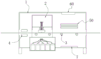
FIG. 1 is a schematic diagram of the structure of the present utility model;
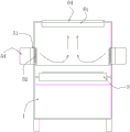
FIG. 2 is a schematic diagram of a blower assembly according to the present utility model;
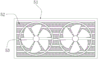
FIG. 3 is a schematic view of an air intake housing according to the present utility model;
FIG. 4 is a schematic diagram of a drying oven according to the present utility model;
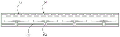
FIG. 5 is a schematic view of the exhaust assembly according to the present utility model;
in the figure: 1. a housing; 2. a printing machine; 3. a conveying roller; 4. a dust remover; 50. an air supply assembly; 51. an air inlet shell; 52. an air deflector; 53. an air intake fan; 54. a drying box; 55. a filter screen; 56. a cover body; 60. an exhaust assembly; 61. an exhaust casing; 62. a fixing frame; 63. an exhaust fan; 64. a dust-proof plate; 7. and a heat preservation lamp.
Detailed Description
The following description of the embodiments of the present utility model will be made clearly and completely with reference to the accompanying drawings, in which it is apparent that the embodiments described are only some embodiments of the present utility model, but not all embodiments. All other embodiments, which can be made by those skilled in the art based on the embodiments of the utility model without making any inventive effort, are intended to be within the scope of the utility model.
Example 1
As shown in fig. 1;
an atomization type ink-jet printing device comprises a shell 1 and a printing machine 2 arranged in the shell 1, wherein an inlet and an outlet are respectively formed in two sides of the shell 1, a rotary conveying roller 3 is arranged on the inner wall of the shell 1, and a dust remover 4 is arranged at the position, close to the inlet, of the shell 1;
in this embodiment: the plastic film product is used for packaging, and the plastic film is printed with patterns, so that the packaging of the product is more exquisite, the difference of products can be conveniently distinguished, and a printing device is used for printing the patterns;
through investigation publication (bulletin) number: CN213619027U discloses a digital printing device convenient for high-efficiency ink-jet, which discloses in the technology that the device comprises a main body, a dust remover and a wind-up roll, wherein the front surface of the main body is provided with an unreeling roll, the dust remover is arranged above the unreeling roll, a printing chamber is arranged on the right side of the dust remover, and a conveying component is arranged below the printing chamber; the device has the technical effects that the filter cartridge and the atomizing pump are arranged to realize multistage filtration of the transported ink, so that the internal impurities are reduced, the fine sliding of the ink is ensured, the transport efficiency is improved, the inkjet efficiency is improved, and the like;
however, when the printing equipment prints on the plastic film, along with long-time printing operation, moisture volatilized by the ink is easily accumulated in the equipment, so that the later printing is in a more humid environment, the plastic film is easily stained with dust when the ink is not dried, the shaping of printed patterns is not facilitated, even if the printing equipment prints by using quick-drying ink, the situation can occur after long-time printing, the printing environment with higher humidity not only affects the quality of the printed patterns, but also affects the service life of the equipment, and the use of users is inconvenient; in order to solve the above problems, the following modifications are proposed.
Further, the method comprises the following steps:
as shown in fig. 1-5;
in combination with the above:
in order to prevent the evaporation of ink accumulated in the shell 1 from generating water vapor, two symmetrically arranged air supply assemblies 50 are arranged on the inner wall of the shell 1, each air supply assembly 50 comprises an air inlet shell 51 penetrating through and fixed on the inner wall of the shell 1, a plurality of air deflectors 52 which are vertically arranged and obliquely downwards arranged are arranged on the inner wall of one side of the air inlet shell 51, which is positioned in the shell 1, and an air inlet fan 53 is arranged on the inner wall of one side of the air inlet shell 51, which is positioned outside the shell 1.
In this embodiment: when the printer 2 performs a printing operation, the air intake fan 53 is started, and the external air passes through the air intake fan 53 to the air deflector 52 and reaches the surface of the film after passing through the air deflector 52, so that the drying speed of the ink is increased, and the air is continuously introduced into the casing 1, so that the accumulation of moisture in the casing 1 can be avoided.
Still further, the method comprises:
in order to further increase the drying speed of the ink, the inside of the housing 1 is kept dry, a drying box 54 with an open top is fixed on the outer side wall of the air inlet housing 51, filter screens 55 are fixed on both sides of the outer side wall of the drying box 54, the drying box 54 is communicated with the air inlet housing 51 through the filter screens 55, and the drying box 54 is filled with a drying agent.
In this embodiment: through the design, the air entering the air inlet fan 53 passes through the drying box 54, the air enters from the filter screen 55 on one side of the drying box 54, the air enters the air inlet fan 53 from the filter screen 55 on the other side after moisture is absorbed by the drying agent, and then enters the shell 1, so that the drying speed of the ink in the shell 1 can be further improved, and the printing quality is improved.
Still further, the method comprises:
in an alternative embodiment, the top side of the drying box 54 is hinged with a cover 56.
In this embodiment: through this design, the open-top drying cabinet 54 facilitates the user to replace the drying agent in time, and the cover 56 can avoid foreign matters from falling into the drying cabinet 54 to affect the drying effect.
Still further, the method comprises:
in an alternative embodiment, an exhaust assembly 60 is mounted on the top inner wall of the housing 1 near the air inlet housing 51, the exhaust assembly 60 includes an exhaust housing 61 penetrating the inner wall of the housing 1, and a plurality of exhaust fans 63 are fixed on the inner wall of the exhaust housing 61 through a fixing frame 62.
In this embodiment: with this design, when printing is performed, the exhaust fan 63 is turned on, the exhaust fan 63 pumps out the air in the housing 1 to the outside, and when the air supply assembly 50 is matched, an air duct as shown in fig. 2 can be formed, so that the drying speed of the ink is further improved.
Still further, the method comprises:
in an alternative embodiment, a plurality of dust-proof plates 64 are fixed on the inner wall of the exhaust casing 61 near the top of the exhaust fan 63, the dust-proof plates 64 are arranged in two rows at equal intervals in the transverse direction, and the two rows of the exhaust casings 61 are staggered.
In this embodiment: with this design, when the printing work is stopped, the dust-proof plates 64 are arranged laterally at equal intervals, and the dust-proof plates 64 form an entire plane in the vertical direction of the exhaust housing 61, so that dust can be prevented from falling into the housing 1.
Still further, the method comprises:
in an alternative embodiment, a heat preservation lamp 7 is mounted on the bottom inner wall of the housing 1 near the blower assembly 50.
In this embodiment: through this design, heat preservation lamp 7 can make the temperature rise in casing 1 to improve the desiccation speed of printing ink, cooperation air supply assembly 50 and exhaust assembly 60 can further improve the desiccation speed of printing ink, make the pattern of printing on the plastic film design when leaving casing 1, avoid dust in the external air to glue on the printing pattern, thereby improved the print quality.
To sum up: the electric equipment in the utility model is electrically connected with an external power supply.
The working principle and the using flow of the utility model are as follows: when the printer 2 performs printing operation, the air inlet fan 53 is started, the air entering the air inlet fan 53 passes through the drying box 54 firstly, the air enters from the filter screen 55 on one side of the drying box 54, after moisture is absorbed by the drying agent, the air enters from the filter screen 55 on the other side into the air inlet fan 53 and then enters the air deflector 52, and the air reaches the surface of a film after passing through the air deflector 52, so that the drying speed of the ink is accelerated, the exhaust fan 63 is started, the air in the shell 1 is pumped out to the outside by the exhaust fan 63, when the air supply assembly 50 is matched, an air channel as shown in fig. 2 can be formed, the drying speed of the ink is further improved, the temperature in the shell 1 can be increased by the heat preservation lamp 7, so that the drying speed of the ink is improved, and when the air supply assembly 50 and the air exhaust assembly 60 are matched, the drying speed of the ink is further improved, the patterns printed on the plastic film are shaped when the patterns leave the shell 1, the dust in the outside air is prevented from being stuck on the printed patterns, so that the printing quality is improved; when the printing operation is stopped, the dust-proof plates 64 are arranged laterally at equal intervals, and the dust-proof plates 64 form an entire plane in the vertical direction of the air-discharge casing 61, preventing dust from falling into the casing 1; the utility model has simple operation, can prevent the printer 2 from being damaged due to the moisture of the working environment, and simultaneously improves the drying speed of the ink and the printing quality.
Finally, it should be noted that: the foregoing description is only a preferred embodiment of the present utility model, and the present utility model is not limited thereto, but it is to be understood that modifications and equivalents of some of the technical features described in the foregoing embodiments may be made by those skilled in the art, although the present utility model has been described in detail with reference to the foregoing embodiments. Any modification, equivalent replacement, improvement, etc. made within the spirit and principle of the present utility model should be included in the protection scope of the present utility model.
Claims (6)
1. The utility model provides an atomizing inkjet printing device, includes casing (1) and installs printing machine (2) in casing (1), entry and export have been seted up respectively to the both sides of casing (1), pivoted transfer roller (3) are installed to the inner wall of casing (1), casing (1) are close to entry department installs dust remover (4), its characterized in that: the air supply assembly comprises an air supply assembly (50) which is symmetrically arranged on the inner wall of a shell (1), the air supply assembly (50) comprises an air inlet shell (51) which penetrates through and is fixed on the inner wall of the shell (1), a plurality of air deflectors (52) which are vertically arranged and obliquely downwards arranged are arranged on the inner wall of one side of the air inlet shell (51) in the shell (1), and an air inlet fan (53) is arranged on the inner wall of one side of the air inlet shell (51) outside the shell (1).
2. The atomizing inkjet printing apparatus according to claim 1 wherein: the drying box is characterized in that a drying box (54) with an open top is fixed on the outer side wall of the air inlet shell (51), a filter screen (55) is fixed on two sides of the outer side wall of the drying box (54), the drying box (54) is communicated with the air inlet shell (51) through the filter screen (55), and a drying agent is filled in the drying box (54).
3. The atomizing inkjet printing apparatus according to claim 2 wherein: the top side of the drying box (54) is hinged with a cover body (56).
4. The atomizing inkjet printing apparatus according to claim 1 wherein: the top inner wall of casing (1) is close to the position department of air inlet casing (51) installs subassembly of airing exhaust (60), subassembly of airing exhaust (60) are including running through exhaust casing (61) of casing (1) inner wall, the inner wall of exhaust casing (61) is fixed with a plurality of exhaust fans (63) through mount (62).
5. The atomizing inkjet printing apparatus according to claim 4 wherein: the inner wall of the exhaust shell (61) is close to the top of the exhaust fan (63) and is fixedly provided with a plurality of dust-proof plates (64), the dust-proof plates (64) are transversely arranged at equal intervals to form two rows, and the two rows of the exhaust shells (61) are staggered.
6. The atomizing inkjet printing apparatus according to claim 1 wherein: and a heat preservation lamp (7) is arranged at the position, close to the air supply assembly (50), of the inner wall of the bottom of the shell (1).
Priority Applications (1)
| Application Number | Priority Date | Filing Date | Title |
|---|---|---|---|
| CN202320053237.0U CN219115081U (en) | 2023-01-09 | 2023-01-09 | Atomizing type ink-jet printing device |
Applications Claiming Priority (1)
| Application Number | Priority Date | Filing Date | Title |
|---|---|---|---|
| CN202320053237.0U CN219115081U (en) | 2023-01-09 | 2023-01-09 | Atomizing type ink-jet printing device |
Publications (1)
| Publication Number | Publication Date |
|---|---|
| CN219115081U true CN219115081U (en) | 2023-06-02 |
Family
ID=86526259
Family Applications (1)
| Application Number | Title | Priority Date | Filing Date |
|---|---|---|---|
| CN202320053237.0U Active CN219115081U (en) | 2023-01-09 | 2023-01-09 | Atomizing type ink-jet printing device |
Country Status (1)
| Country | Link |
|---|---|
| CN (1) | CN219115081U (en) |
-
2023
- 2023-01-09 CN CN202320053237.0U patent/CN219115081U/en active Active
Similar Documents
| Publication | Publication Date | Title |
|---|---|---|
| CN214395899U (en) | Environment-friendly packing printing device | |
| JP2024163289A (en) | Inkjet printer | |
| CN217753237U (en) | Energy-conserving high-efficient digital printing device | |
| JP6604858B2 (en) | Inkjet printing device | |
| JP2014180784A (en) | Airflow generation device and image formation device | |
| CN210257645U (en) | Drying equipment for printing | |
| CN210916799U (en) | A drying device for thermal paper production | |
| CN119773359A (en) | Packaging box production printing device with drying mechanism | |
| CN213082712U (en) | Energy-saving printer ink-jet improvement mechanism | |
| CN215435619U (en) | Air cooling mechanism of inkjet printer for media advertisement and inkjet printer | |
| CN223237227U (en) | Quick drying mechanism | |
| JP2007505764A (en) | Sheet offset machine, dryer and method for drying in sheet offset machine | |
| CN222329288U (en) | Environment-friendly carton printing machine | |
| CN101721165A (en) | Vacuum dust collector | |
| CN209694038U (en) | A kind of novel tobacco coating drying stoving rack | |
| CN220095902U (en) | Printed calico stoving dust collector | |
| CN214492073U (en) | Intermittent PS (polystyrene) plate trademark green printing machine | |
| CN221457127U (en) | Paper drying mechanism of color printer | |
| CN208469285U (en) | A drying device for a rotary screen printing machine | |
| CN220785253U (en) | Drying device that air brushing was used | |
| CN214449324U (en) | Printing roller cooling device for printing equipment | |
| CN221540987U (en) | Integrative device of printing stoving | |
| CN221698251U (en) | Stamp drying device | |
| CN216733591U (en) | A drying inkjet printer | |
| CN216942296U (en) | A semi-closed digital printing equipment |
Legal Events
| Date | Code | Title | Description |
|---|---|---|---|
| GR01 | Patent grant | ||
| GR01 | Patent grant |