CN219103911U - TIP head pipe installation location and pine take off and detect frock - Google Patents
TIP head pipe installation location and pine take off and detect frock Download PDFInfo
- Publication number
- CN219103911U CN219103911U CN202223065527.1U CN202223065527U CN219103911U CN 219103911 U CN219103911 U CN 219103911U CN 202223065527 U CN202223065527 U CN 202223065527U CN 219103911 U CN219103911 U CN 219103911U
- Authority
- CN
- China
- Prior art keywords
- positioning
- plate
- threaded rod
- tip head
- head pipe
- Prior art date
- Legal status (The legal status is an assumption and is not a legal conclusion. Google has not performed a legal analysis and makes no representation as to the accuracy of the status listed.)
- Active
Links
- 238000009434 installation Methods 0.000 title claims abstract description 44
- 235000008331 Pinus X rigitaeda Nutrition 0.000 title claims description 18
- 235000011613 Pinus brutia Nutrition 0.000 title claims description 18
- 241000018646 Pinus brutia Species 0.000 title claims description 18
- 238000001514 detection method Methods 0.000 claims abstract description 26
- 230000003287 optical effect Effects 0.000 claims description 24
- 239000011241 protective layer Substances 0.000 claims description 2
- 239000003153 chemical reaction reagent Substances 0.000 description 5
- 239000011248 coating agent Substances 0.000 description 1
- 238000000576 coating method Methods 0.000 description 1
- 238000010586 diagram Methods 0.000 description 1
- 238000003018 immunoassay Methods 0.000 description 1
- 238000005259 measurement Methods 0.000 description 1
- 238000000034 method Methods 0.000 description 1
- 238000002156 mixing Methods 0.000 description 1
- 238000012986 modification Methods 0.000 description 1
- 230000004048 modification Effects 0.000 description 1
- 230000008092 positive effect Effects 0.000 description 1
- 238000003756 stirring Methods 0.000 description 1
- 238000006467 substitution reaction Methods 0.000 description 1
Images


Classifications
-
- Y—GENERAL TAGGING OF NEW TECHNOLOGICAL DEVELOPMENTS; GENERAL TAGGING OF CROSS-SECTIONAL TECHNOLOGIES SPANNING OVER SEVERAL SECTIONS OF THE IPC; TECHNICAL SUBJECTS COVERED BY FORMER USPC CROSS-REFERENCE ART COLLECTIONS [XRACs] AND DIGESTS
- Y02—TECHNOLOGIES OR APPLICATIONS FOR MITIGATION OR ADAPTATION AGAINST CLIMATE CHANGE
- Y02E—REDUCTION OF GREENHOUSE GAS [GHG] EMISSIONS, RELATED TO ENERGY GENERATION, TRANSMISSION OR DISTRIBUTION
- Y02E30/00—Energy generation of nuclear origin
- Y02E30/30—Nuclear fission reactors
Landscapes
- Conveying And Assembling Of Building Elements In Situ (AREA)
- Manipulator (AREA)
- Lining And Supports For Tunnels (AREA)
Abstract
The utility model discloses a TIP head pipe installation, positioning and loosening detection tool, which is characterized by comprising the following components: the device comprises a bottom plate, an alignment plate, a positioning structure, a driving structure, a fixing structure and a limiting structure; the lower end of the positioning structure is arranged on the bottom plate, and the upper end of the positioning structure is close to or far away from the alignment plate; the lower end of the fixing structure is arranged on the positioning structure, and the upper end of the fixing structure is arranged on the alignment plate; the lower end of the driving structure is arranged on the positioning structure, the upper end of the driving structure is propped against the alignment plate, and the driving structure drives the alignment plate to move up and down relative to the bottom plate; the limiting structure is arranged on the driving mechanism, and the limiting mechanism enables the driving structure to be located at the highest station and the lowest station. The tool has two purposes and practicability. The device is simple in structure and can effectively save cost.
Description
Technical Field
The utility model relates to the related technical fields of medical appliances and the like, in particular to a TIP head tube installation, positioning and loosening detection tool.
Background
In the chemiluminescent immunoassay analyzer, the reagents in a plurality of reagent strips in a batch are subjected to operations such as pipetting, stirring and mixing through a disposable TIP head fixed on a TIP head tube, and the steps of loading and unloading the disposable TIP head are carried out before and after the operations, and the plurality of TIP head tubes are synchronously operated, if the TIP head tube is not in place during installation or is loosened during operation, the connection between the TIP head tube and the disposable TIP head is not tight, and further the pipetting accuracy is beyond an allowable range, so that the measurement result is inaccurate. However, the existing positioning structure for positioning the TIP head pipe cannot position the TIP head pipe which is being installed and after installation. And cannot effectively measure whether the TIP header connection is tight.
Disclosure of Invention
In view of the above, the present utility model provides a TIP head pipe installation, positioning and loosening detection tool, comprising:
the device comprises a bottom plate, an alignment plate, a positioning structure, a driving structure, a fixing structure and a limiting structure;
the lower end of the positioning structure is arranged on the bottom plate, and the upper end of the positioning structure is close to or far away from the alignment plate;
the lower end of the fixing structure is arranged on the positioning structure, and the upper end of the fixing structure is arranged on the alignment plate;
the lower end of the driving structure is arranged on the positioning structure, the upper end of the driving structure is propped against the alignment plate, and the driving structure drives the alignment plate to move up and down relative to the bottom plate;
the limiting structure is arranged on the driving structure, and the limiting structure enables the driving structure to be located at the highest station and the lowest station.
Foretell a TIP head pipe installation location and pine take off and detect frock, wherein, location structure includes: two linear optical axes, two linear bearings, a top plate and a connecting plate; the upper ends of the two linear optical axes are arranged on the top plate, the lower ends of the two linear optical axes penetrate through the two ends of the connecting plate and are arranged on the bottom plate, the two linear bearings are respectively sleeved on the two linear optical axes, and the two linear bearings are fixedly arranged on the connecting plate.
Foretell a TIP head pipe installation location and pine take off and detect frock, wherein, fixed knot constructs includes: the upper ends of the connecting columns penetrate through the top plate to be installed on the alignment plate, the lower ends of the connecting columns are installed on the connecting plate, the pressure springs are sleeved on the connecting columns, and the two ends of the pressure springs are respectively propped against the top plate and the connecting plate.
Foretell a TIP head pipe installation location and pine take off and detect frock, wherein, drive structure includes: a threaded rod; the upper end of the threaded rod penetrates through the top plate to be installed on the alignment plate, the lower end of the threaded rod is movably installed on the alignment plate, and the threaded rod drives the alignment plate to move up and down relative to the bottom plate.
Foretell a TIP head pipe installation location and pine take off and detect frock, wherein, limit structure includes: a sleeve and a screw; the sleeve is sleeved on the threaded rod, and the screw is installed on the bottom plate.
Foretell a TIP head pipe installation location and pine take off and detect frock, wherein, still include: the six-star plum blossom handle is arranged at the lower end of the threaded rod pair, and is close to or far away from the screw.
Foretell a TIP head pipe installation location and pine take off and detect frock, wherein, still include: the boss is arranged on the threaded rod through the six-star plum blossom handle.
The TIP head pipe installation, positioning and loosening detection tool comprises a connecting column, a threaded rod, a connecting column and a connecting rod.
According to the TIP head pipe installation, positioning and loosening detection tool, the upper surface of the screw is provided with the protective layer.
The TIP head pipe installation, positioning and loosening detection tool is characterized in that two positioning holes are formed in the bottom plate.
Compared with the prior art, the technical scheme has the following positive effects:
through the application of the utility model, a TIP head pipe installation positioning and loosening detection tool is provided, a bottom plate is fixedly arranged on a fixed table in the device, the whole device is opposite to the TIP head pipe of an instrument, a driving structure is manually moved, the driving structure moves upwards on the positioning structure, thereby driving an alignment plate to move upwards, a limiting structure limits the highest working position and the lowest working position of the alignment plate, when the alignment plate moves to the highest working position, the lower end of the TIP head pipe is sequentially and fixedly arranged on a reagent strip frame against the alignment plate, finally, a clearance between the TIP head pipe and the alignment plate is sequentially checked by a 5mm feeler gauge, and the feeler gauge cannot be plugged into the clearance, so that the installation is qualified. Each TIP head tube can be fixedly arranged on the reagent strip rack, the using method of the device is convenient, a conclusion can be directly judged by plugging a feeler gauge, no reading is needed, and the device is convenient to use; when the installed TIP head pipe needs to be detected whether to loosen, the alignment plate is moved to the lowest working position, and then the alignment plate is moved upwards until the alignment plate abuts against the TIP head pipe, so that whether the TIP head pipe loosens is detected. The device has the functions of TIP head installation and positioning and looseness detection, and has two purposes of one tool and practicability. The device is simple in structure and can effectively save cost.
Drawings
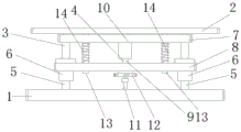
Fig. 1 is a front view of a TIP head tube installation positioning and loosening detection tool of the present utility model.
Fig. 2 is a cross-sectional view of a TIP head tube installation positioning and loosening detection tool of the present utility model.
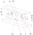
Fig. 3 is a perspective view of a TIP head tube installation positioning and loosening detection tool of the present utility model.
Fig. 4 is a schematic diagram illustrating the use of a TIP tube installation positioning and loosening detection tool according to the present utility model.
1. A bottom plate; 2. an alignment plate; 3. a positioning structure; 4. a driving structure; 5. a straight optical axis; 6. a linear bearing; 7. a top plate; 8. a connecting plate; 9. a threaded rod; 10. a sleeve; 11. a screw; 12. a six-star plum blossom handle; 13. a connecting column; 14. a pressure spring; 15. a boss; 16. positioning holes; 17. TIP head tube.
Detailed Description
The utility model is further described below, but is not limited to, with reference to the drawings and detailed description.
The structures, proportions, sizes, etc. shown in the drawings attached hereto are for illustration purposes only and are not intended to limit the scope of the utility model, which is defined by the claims, but rather by the claims. Also, the terms such as "upper," "lower," "left," "right," "middle," and "a" and the like recited in the present specification are merely for descriptive purposes and are not intended to limit the scope of the utility model, but are intended to provide relative positional changes or modifications without materially altering the technical context in which the utility model may be practiced.
As shown in fig. 1 to 4, a TIP head pipe installation positioning and loosening detection tool according to a preferred embodiment includes: the device comprises a bottom plate 1, an alignment plate 2, a positioning structure 3, a driving structure 4, a fixing structure and a limiting structure.
The lower end of the positioning structure 3 is arranged on the bottom plate 1, and the upper end of the positioning structure 3 is close to or far away from the alignment plate 2; the lower end of the fixing structure is arranged on the positioning structure 3, and the upper end of the fixing structure is arranged on the alignment plate; the lower end of the driving structure 4 is arranged on the positioning structure 3, the upper end of the driving structure 4 is propped against the alignment plate 2, and the driving structure 4 drives the alignment plate 2 to move up and down relative to the bottom plate 1; the limiting structure is arranged on the driving structure 4, and the limiting structure enables the driving structure 4 to be positioned at the highest station and the lowest station.
When the TIP head tube is installed and positioned, firstly, the bottom plate 1 is fixed on a fixed table, the whole TIP head tube is directly opposite to the TIP head tube, then the driving structure 4 is manually moved, the driving structure 4 can drive the alignment plate 2 to move up and down, when the driving structure 4 drives the alignment plate 2 to move up until the alignment plate 2 moves to the highest station, the highest station at the moment is the highest height of the upward movement of the alignment plate 2, namely the positioning position of the TIP head tube 17, and then the lower end of the TIP head tube 17 is sequentially supported against the alignment plate 2 and is fixed on a reagent strip frame; finally, checking the gap between the TIP head pipe 17 and the alignment plate 2 in sequence by using a 0.5mm feeler gauge, and installing the feeler gauge qualified if the feeler gauge cannot be plugged into the gap. So that the plurality of TIP head pipes 17 can be in a fixed positioning position when the plurality of TIP head pipes 17 are installed.
When the TIP head pipe 17 is loosened and detected, the limiting structure 4 is manually moved firstly, the limiting structure 4 can limit the highest station and the lowest station of the alignment plate 2, when the limiting structure 4 drives the alignment plate 2 to move to the lowest station, the lowest station at the moment is the position where the alignment plate 2 is in contact with the upper end of the positioning structure 3, then the bottom plate 1 is fixed on a fixed table, the whole device is opposite to the TIP head pipe 17, then the limiting structure 4 is moved until the alignment plate 2 props against the TIP head pipe 17, a clearance between the TIP head pipe 17 and the alignment plate 2 is sequentially checked by using a 0.5mm feeler, the feeler cannot be plugged into the clearance, and if the clearance can be plugged into the feeler, the TIP head pipe is loosened and needs to be reinstalled and fixed.
The present utility model has the following embodiments based on the above description:
further, a TIP head pipe installation location and pine take off and detect frock, wherein, location structure 3 includes: two linear optical axes 5, two linear bearings 6, a top plate 7 and a connecting plate 8; the upper ends of the two linear optical axes 5 are arranged on the top plate 7, the lower ends of the two linear optical axes 5 penetrate through two ends of the connecting plate 8 and are arranged on the bottom plate 1, the two linear bearings 6 are respectively sleeved on the two linear optical axes 5, and the two linear bearings 6 are fixedly arranged on the connecting plate 8. Specifically, the top ends of the two linear optical axes 5 are fixedly mounted on the top plate 7 through screws, and two grooves are formed in the lower end of the alignment plate 2 and used for avoiding the screws for mounting the linear optical axes 5, when the alignment plate 2 is located above the top plate 7 and the two alignment plate are abutted, screw heads of the two screws for mounting the two linear optical axes 5 are located in the two grooves, namely, the position of the lowest station is the position. The two linear bearings 6 move up and down in the direction along the two linear optical axes 5, thereby driving the connection plates 8 mounted on the two linear bearings 6 to move up and down in the direction along the linear optical axes 5.
Further, a TIP head pipe installation location and pine take off and detect frock, wherein, fixed knot constructs and includes: the upper ends of the two connecting columns 13 penetrate through the top plate 7 and are mounted on the alignment plate 2, the lower ends of the two connecting columns 13 are mounted on the connecting plate 8, the two connecting columns 13 are sleeved with the two pressure springs 14, and two ends of the two pressure springs 14 respectively abut against the top plate 7 and the connecting plate 8.
Further, a TIP head pipe installation location and pine take off and detect frock, wherein, drive structure 4 includes: a threaded rod 9; the upper end of the threaded rod 9 passes through the top plate 7 to be mounted on the alignment plate 2, and the lower end of the threaded rod 9 passes through the connecting plate 8 to be close to or far from the screw 11. Specifically, the lower end of the threaded rod 9 is movably mounted on the alignment plate 2, and the threaded rod 9 drives the alignment plate 2 to move up and down relative to the bottom plate 1. The lower end of the threaded rod 9 is held by hand, the threaded rod 9 is rotated, the threaded rod 9 moves upwards to drive the connecting plate 8 to move upwards, the connecting plate 8 drives the linear bearing 6 to move upwards along the linear optical axis 5, and the upper end of the threaded rod 9 drives the alignment plate 2 to move upwards.
Further, a TIP head pipe installation location and pine take off and detect frock, wherein, limit structure includes: a sleeve 10 and a screw 11; the sleeve 10 is sleeved on the threaded rod 9, and the screw 11 is mounted on the bottom plate. In particular, when the connection plate 8 moves upwards until it abuts against the sleeve 10, the threaded rod 9 no longer moves, this position being the highest position of the alignment plate 2. When the lower end of the threaded rod 9 is held by hand, the threaded rod 9 is rotated, so that the threaded rod 9 moves downwards, the lower end of the threaded rod 9 drives the connecting plate 8 to move downwards at the moment, the upper end of the threaded rod 9 drives the alignment plate 2 to move downwards, the connecting plate 8 drives the linear bearing 6 to move downwards along the linear optical axis 5, and when the lower end of the threaded rod 9 abuts against the screw 11, the alignment plate 2 is at the lowest station at the moment.
Further, a TIP head pipe installation location and pine take off and detect frock, wherein, still includes: the six-star plum blossom handle 12, the six-star plum blossom handle 12 is installed in the lower extreme of threaded rod 9. Specifically, the six-star plum blossom handle 12 is arranged at the lower end of the threaded rod 9, and the six-star plum blossom handle 12 can be directly rotated so as to rotate the threaded rod 9, so that the use is convenient and labor-saving.
Further, a TIP head pipe installation location and pine take off and detect frock, wherein, still include: the boss, six star plum blossom handle 12 is installed in threaded rod 9's lower extreme through the boss. Specifically, two connecting posts 13 are respectively sleeved with a pressure spring 14, one end of the pressure spring 14 is in a compressed state, the other end of the pressure spring is propped against the top plate 7, and the other end of the pressure spring is propped against the connecting plate 8, so that the lower end face of the connecting plate 8 is always attached to a boss of the six-star plum blossom handle 12.
Further, a TIP head pipe installation positioning and loosening detection tool, wherein one connecting column 13 is located between one linear optical axis 5 and the threaded rod 9, and the other connecting column 13 is located between the other linear optical axis 5 and the threaded rod 9.
Further, a TIP head pipe installation location and pine takes off detection frock, wherein, the upper surface of screw 11 is equipped with a inoxidizing coating. Specifically, when the screw 11 abuts against the six-star plum blossom handle 12, the surface of the six-star plum blossom handle 12 is protected. Is not easy to scratch.
Further, a TIP head pipe installation location and pine take off detection frock, wherein, be equipped with two locating holes 16 on the bottom plate 1. Specifically, the base plate 1 is mounted on the stationary table through the positioning holes 16.
Further, a TIP head pipe installation location and pine takes off and detects frock, the upper end of threaded rod 9 and alignment board 2 can be fixed connection or swing joint, and when the upper end of threaded rod 9 and alignment board 2 were swing joint, the lower extreme of alignment board 2 was equipped with the recess, and the upper end of threaded rod 9 supports in the recess, and the deformation of accessible pressure spring 14 makes alignment board 2 resume the position this moment. When the upper end of the threaded rod 9 is fixedly connected with the alignment plate 2, the threaded rod 9 directly drives the alignment plate 2 to move up and down.
The foregoing description is only illustrative of the preferred embodiments of the present utility model and is not to be construed as limiting the scope of the utility model, and it will be appreciated by those skilled in the art that equivalent substitutions and obvious variations may be made using the description and illustrations of the present utility model, and are intended to be included within the scope of the present utility model.
Claims (10)
1. TIP head pipe installation location and pine take off detection frock, its characterized in that includes:
the device comprises a bottom plate, an alignment plate, a positioning structure, a driving structure, a fixing structure and a limiting structure;
the lower end of the positioning structure is arranged on the bottom plate, and the upper end of the positioning structure is close to or far away from the alignment plate;
the lower end of the fixing structure is arranged on the positioning structure, and the upper end of the fixing structure is arranged on the alignment plate;
the lower end of the driving structure is arranged on the positioning structure, the upper end of the driving structure is propped against the alignment plate, and the driving structure drives the alignment plate to move up and down relative to the bottom plate;
the limiting structure is arranged on the driving structure, and the limiting structure enables the driving structure to be located at the highest station and the lowest station.
2. The TIP head pipe installation, positioning and loosening detection tool according to claim 1, wherein the positioning structure comprises: two linear optical axes, two linear bearings, a top plate and a connecting plate; the upper ends of the two linear optical axes are arranged on the top plate, the lower ends of the two linear optical axes penetrate through the two ends of the connecting plate and are arranged on the bottom plate, the two linear bearings are respectively sleeved on the two linear optical axes, and the two linear bearings are fixedly arranged on the connecting plate.
3. The TIP head pipe installation, positioning and loosening detection tool according to claim 2, wherein the fixing structure comprises: the upper ends of the connecting columns penetrate through the top plate to be installed on the alignment plate, the lower ends of the connecting columns are installed on the connecting plate, the pressure springs are sleeved on the connecting columns, and the two ends of the pressure springs are respectively propped against the top plate and the connecting plate.
4. A TIP head pipe installation location and release detection tool as defined in claim 3, wherein said drive structure comprises: a threaded rod; the upper end of the threaded rod penetrates through the top plate to be installed on the alignment plate, the lower end of the threaded rod is movably installed on the alignment plate, and the threaded rod drives the alignment plate to move up and down relative to the bottom plate.
5. The TIP head pipe installation, positioning and loosening detection tool according to claim 4, wherein the limiting structure comprises: a sleeve and a screw; the sleeve is sleeved on the threaded rod, and the screw is installed on the bottom plate.
6. The TIP head pipe installation, positioning and loosening detection tool as set forth in claim 5, further comprising: the six-star plum blossom handle is arranged at the lower end of the threaded rod, and the six-star plum blossom handle is close to or far away from the screw.
7. The TIP head pipe installation, positioning and loosening detection tool as set forth in claim 6, further comprising: the boss is arranged on the threaded rod through the six-star plum blossom handle.
8. The TIP tube installation positioning and loosening detection tool as set forth in claim 4, wherein one of said connecting posts is located between one of said linear optical axis and said threaded rod and the other of said connecting posts is located between the other of said linear optical axis and said threaded rod.
9. The TIP tube installation positioning and loosening detection tool according to claim 5, wherein a protective layer is arranged on the upper surface of the screw.
10. The TIP tube installation positioning and loosening detection tool according to claim 1, wherein two positioning holes are formed in the bottom plate.
Priority Applications (1)
| Application Number | Priority Date | Filing Date | Title |
|---|---|---|---|
| CN202223065527.1U CN219103911U (en) | 2022-11-18 | 2022-11-18 | TIP head pipe installation location and pine take off and detect frock |
Applications Claiming Priority (1)
| Application Number | Priority Date | Filing Date | Title |
|---|---|---|---|
| CN202223065527.1U CN219103911U (en) | 2022-11-18 | 2022-11-18 | TIP head pipe installation location and pine take off and detect frock |
Publications (1)
| Publication Number | Publication Date |
|---|---|
| CN219103911U true CN219103911U (en) | 2023-05-30 |
Family
ID=86464055
Family Applications (1)
| Application Number | Title | Priority Date | Filing Date |
|---|---|---|---|
| CN202223065527.1U Active CN219103911U (en) | 2022-11-18 | 2022-11-18 | TIP head pipe installation location and pine take off and detect frock |
Country Status (1)
| Country | Link |
|---|---|
| CN (1) | CN219103911U (en) |
-
2022
- 2022-11-18 CN CN202223065527.1U patent/CN219103911U/en active Active
Similar Documents
| Publication | Publication Date | Title |
|---|---|---|
| CN109405717B (en) | Automatic roundness detection system for shaft workpieces | |
| WO2019109527A1 (en) | Tester | |
| CN115290025A (en) | High-speed fan blade is multidimension degree verifying attachment for product | |
| CN210005361U (en) | rigidity testing device | |
| CN217638346U (en) | Rock hardness detection device based on geological survey usefulness | |
| CN220829170U (en) | Level measuring device for architectural design | |
| CN215448739U (en) | Bending test jig | |
| CN219589612U (en) | Linear module detection device | |
| CN215177385U (en) | Detection tool for detecting sensor | |
| CN216348166U (en) | Adjustable multi-detection-position detection tool for front-end frame assembly | |
| CN115446873A (en) | Industrial robot's positioning accuracy measuring device | |
| CN211651412U (en) | Checking fixture for quickly measuring position degree of part | |
| CN200955946Y (en) | An inner width detection device | |
| CN219390756U (en) | Gauge tool convenient to detect | |
| CN210533229U (en) | Motor shaft extension size detection device | |
| CN114322820A (en) | Fastener hole degree of depth detects frock | |
| CN208187434U (en) | Detector regulating device | |
| CN108917812B (en) | Detector adjustment device and method of operation thereof | |
| CN219223689U (en) | Height measuring device | |
| CN223332288U (en) | Automatic detection device of length comparator | |
| CN223741447U (en) | A device for accurately detecting the depth of a pinhole | |
| CN218822115U (en) | Perpendicularity detection tool | |
| CN220583288U (en) | Hole center distance measuring instrument | |
| CN2852044Y (en) | Apparatus for detecting cast profiled hole surface wall thickness | |
| CN220507927U (en) | Contour degree detection pin |
Legal Events
| Date | Code | Title | Description |
|---|---|---|---|
| GR01 | Patent grant | ||
| GR01 | Patent grant |