CN219094492U - Composite feed type numerical control lathe - Google Patents
Composite feed type numerical control lathe Download PDFInfo
- Publication number
- CN219094492U CN219094492U CN202223046946.0U CN202223046946U CN219094492U CN 219094492 U CN219094492 U CN 219094492U CN 202223046946 U CN202223046946 U CN 202223046946U CN 219094492 U CN219094492 U CN 219094492U
- Authority
- CN
- China
- Prior art keywords
- fixedly connected
- chip removal
- machine case
- pipe
- machine
- Prior art date
- Legal status (The legal status is an assumption and is not a legal conclusion. Google has not performed a legal analysis and makes no representation as to the accuracy of the status listed.)
- Active
Links
- 239000002131 composite material Substances 0.000 title abstract description 6
- 239000007788 liquid Substances 0.000 claims abstract description 15
- 239000002893 slag Substances 0.000 claims abstract description 10
- XLYOFNOQVPJJNP-UHFFFAOYSA-N water Substances O XLYOFNOQVPJJNP-UHFFFAOYSA-N 0.000 claims description 11
- 150000001875 compounds Chemical class 0.000 claims description 8
- 230000017525 heat dissipation Effects 0.000 claims description 3
- 239000002699 waste material Substances 0.000 abstract description 7
- 239000002173 cutting fluid Substances 0.000 abstract description 6
- 238000001816 cooling Methods 0.000 abstract description 2
- 238000000034 method Methods 0.000 description 3
- 239000012530 fluid Substances 0.000 description 2
- 238000010923 batch production Methods 0.000 description 1
- 230000009286 beneficial effect Effects 0.000 description 1
- 238000004891 communication Methods 0.000 description 1
- 238000005520 cutting process Methods 0.000 description 1
- 230000000694 effects Effects 0.000 description 1
- 238000005516 engineering process Methods 0.000 description 1
- 238000012423 maintenance Methods 0.000 description 1
- 230000005855 radiation Effects 0.000 description 1
Images
Classifications
-
- Y—GENERAL TAGGING OF NEW TECHNOLOGICAL DEVELOPMENTS; GENERAL TAGGING OF CROSS-SECTIONAL TECHNOLOGIES SPANNING OVER SEVERAL SECTIONS OF THE IPC; TECHNICAL SUBJECTS COVERED BY FORMER USPC CROSS-REFERENCE ART COLLECTIONS [XRACs] AND DIGESTS
- Y02—TECHNOLOGIES OR APPLICATIONS FOR MITIGATION OR ADAPTATION AGAINST CLIMATE CHANGE
- Y02P—CLIMATE CHANGE MITIGATION TECHNOLOGIES IN THE PRODUCTION OR PROCESSING OF GOODS
- Y02P70/00—Climate change mitigation technologies in the production process for final industrial or consumer products
- Y02P70/10—Greenhouse gas [GHG] capture, material saving, heat recovery or other energy efficient measures, e.g. motor control, characterised by manufacturing processes, e.g. for rolling metal or metal working
Landscapes
- Turning (AREA)
Abstract
The utility model discloses a composite feed type numerical control lathe which comprises a machine case, wherein an organic table is fixedly connected to the upper surface of the machine case, a slag guide groove is formed in the upper surface of the machine table, a chip removal guide plate is fixedly connected to the back surface of the machine table, a filter screen is arranged on the bottom surface of the chip removal guide plate, a collecting shell is fixedly connected to the bottom surface of the chip removal guide plate, a connecting pipe is fixedly communicated between the collecting shell and the machine case, a feeding box and a spindle box are respectively installed on the upper surface of the machine table, and a universal pipe is fixedly connected to the upper surface of the feeding box. This device is through setting up the slag chute on the board, and slag chute and chip removal baffle cooperation can be with sweeps and waste liquid discharge, set up the filter screen on chip removal baffle, separate sweeps and waste liquid through the filter screen, wash the cooling of tool bit along with universal pipe spun cutting fluid, make sweeps fall along chip removal baffle, slide in the bottom of quick-witted case and set up the collection frame, pull out the collection frame and conveniently collect the sweeps.
Description
Technical Field
The utility model relates to the field of numerically controlled lathes, in particular to a composite feed type numerically controlled lathe.
Background
The numerical control lathe and the turning center are high-precision and high-efficiency automatic lathes, are provided with multi-station lathes or power lathes, have wide processing performances, can process linear cylinders, oblique cylinders, circular arcs, various complex workpieces such as threads, grooves, worms and the like, have linear interpolation and circular arc interpolation compensation functions, exert good economic effects in batch production of complex parts, and need to cool and lubricate tool bits by using cutting fluid when the numerical control lathe processes the workpieces, but the current cutting scraps are inconvenient to discharge, need to be cleaned later, and cause inconvenient maintenance.
Therefore, we propose a compound feed type numerical control lathe to solve the above problems.
Disclosure of Invention
The utility model aims to provide a composite feed type numerical control lathe so as to solve the problems in the background technology.
In order to achieve the above purpose, the present utility model provides the following technical solutions:
the utility model provides a compound feed formula numerical control lathe, includes the quick-witted case, the upper surface fixed connection organic board of machine case, the slag chute has been seted up to the upper surface of machine board, the back fixedly connected with chip removal baffle of machine board, the bottom surface of chip removal baffle is equipped with the filter screen, the bottom surface fixedly connected with of chip removal baffle collects the shell, it has the connecting pipe to collect fixed intercommunication between shell and the machine case.
In a further embodiment, a feed box and a spindle box are respectively installed on the upper surface of the machine table, and a universal pipe is fixedly connected to the upper surface of the feed box.
In a further embodiment, the inside fixedly connected with fixed plate of quick-witted case, interior bottom wall fixed mounting of quick-witted case has the water pump, the output of water pump fixedly communicates there is the drawing liquid pipe, the drawing liquid pipe is linked together with the fixed plate, the output fixedly communicates there is the drain pipe, the one end and the universal pipe of drain pipe are linked together.
In a further embodiment, two heat dissipation windows are formed in the back of the case, four supporting feet are fixedly connected to the bottom surface of the case, two sliding rails are fixedly mounted on the bottom surface of the case, a collecting frame is slidably connected between the two sliding rails, and a handle is fixedly mounted on the front surface of the collecting frame.
Compared with the prior art, the utility model has the beneficial effects that:
this device is through setting up the slag chute on the board, and slag chute and chip removal baffle cooperation can be with sweeps and waste liquid discharge, set up the filter screen on chip removal baffle, separate sweeps and waste liquid through the filter screen, wash the cooling of tool bit along with universal pipe spun cutting fluid, make sweeps fall along chip removal baffle, slide in the bottom of quick-witted case and set up the collection frame, pull out the collection frame and conveniently collect the sweeps.
Drawings
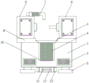
Fig. 1 is a rear view of a compound feed type numerically controlled lathe.
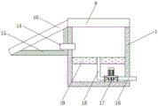
Fig. 2 is a side sectional view of a machine case in the compound feed type numerically controlled lathe.
In the figure: 1. a chassis; 2. a heat radiation window; 3. supporting feet; 4. a filter screen; 5. a slag guide groove; 6. a spindle box; 7. a universal pipe; 8. a feed box; 9. a machine table; 10. a chip removal guide plate; 11. a grip; 12. a collection frame; 13. a slide rail; 14. a connecting pipe; 15. collecting the shell; 16. a liquid outlet pipe; 17. a water pump; 18. a liquid suction pipe; 19. and a fixing plate.
Detailed Description
In the description of the present utility model, it should be understood that the terms "center", "longitudinal", "lateral", "upper", "lower", "front", "rear", "left", "right", "vertical", "horizontal", "top", "bottom", "inner", "outer", etc. indicate orientations or positional relationships based on the orientations or positional relationships shown in the drawings, are merely for convenience in describing the present utility model and simplifying the description, and do not indicate or imply that the devices or elements referred to must have a specific orientation, be configured and operated in a specific orientation, and thus should not be construed as limiting the present utility model. Furthermore, the terms "first," "second," and the like, are used for descriptive purposes only and are not to be construed as indicating or implying a relative importance or implicitly indicating the number of technical features indicated. Thus, a feature defining "a first", "a second", etc. may explicitly or implicitly include one or more such feature. In the description of the present utility model, unless otherwise indicated, the meaning of "a plurality" is two or more.
In the description of the present utility model, it should be noted that, unless explicitly specified and limited otherwise, the terms "mounted," "connected," and "connected" are to be construed broadly, and may be either fixedly connected, detachably connected, or integrally connected, for example; can be mechanically or electrically connected; can be directly connected or indirectly connected through an intermediate medium, and can be communication between two elements. The specific meaning of the above terms in the present utility model can be understood by those of ordinary skill in the art in a specific case.
The following description of the embodiments of the present utility model will be made clearly and completely with reference to the accompanying drawings, in which it is apparent that the embodiments described are only some embodiments of the present utility model, but not all embodiments. All other embodiments, which can be made by those skilled in the art based on the embodiments of the utility model without making any inventive effort, are intended to be within the scope of the utility model.
Referring to fig. 1-2, in the utility model, a composite feed type numerically controlled lathe comprises a machine case 1, wherein an organic table 9 is fixedly connected to the upper surface of the machine case 1, a slag guide groove 5 is formed in the upper surface of the machine table 9, a chip removal guide plate 10 is fixedly connected to the back surface of the machine table 9, a filter screen 4 is arranged on the bottom surface of the chip removal guide plate 10, a collecting shell 15 is fixedly connected to the bottom surface of the chip removal guide plate 10, and a connecting pipe 14 is fixedly communicated between the collecting shell 15 and the machine case 1.
The upper surface of board 9 installs feed box 8 and headstock 6 respectively, the upper surface fixedly connected with universal pipe 7 of feed box 8, conveniently process the work piece through feed box 8 and headstock 6, the inside fixedly connected with fixed plate 19 of quick-witted case 1, the interior bottom wall fixed mounting of quick-witted case 1 has water pump 17, the output fixed intercommunication of water pump 17 has the drawing liquid pipe 18, drawing liquid pipe 18 is linked together with fixed plate 19, the output fixed intercommunication of water pump 17 has drain pipe 16, the one end and the universal pipe 7 of drain pipe 16 are linked together, through water pump 17 cooperation drain pipe 16 and drawing liquid pipe 18, two heat dissipation windows 2 have been seted up to the back of quick-witted case 1, the bottom surface fixedly connected with four supporting legs 3 of quick-witted case 1, the bottom surface fixed mounting of quick-witted case 1 has two slide rails 13, sliding connection has collection frame 12 between two slide rails 13, the front fixed mounting of collection frame 12 has grip 11, conveniently collect the waste residue through collection frame 12.
The working principle of the utility model is as follows:
when the numerical control lathe is used, firstly, the numerical control lathe is placed at a using position through the supporting feet 3, a power supply of the numerical control lathe is connected, when a workpiece is processed, cutting fluid is conveyed to the universal pipe 7 through the water pump 17 in combination with the fluid suction pipe 18 and the fluid outlet pipe 16, the universal pipe 7 discharges the cutting fluid to cool a cutter head, scraps and waste liquid fall into the slag guide groove 5, the filter screen 4 is arranged on the scrap removal guide plate 10, the scraps and the waste liquid are separated through the filter screen 4, and the scraps fall along the scrap removal guide plate 10 along with the cutting fluid sprayed by the universal pipe 7, so that the scraps are cleaned and collected.
It will be evident to those skilled in the art that the utility model is not limited to the details of the foregoing illustrative embodiments, and that the present utility model may be embodied in other specific forms without departing from the spirit or essential characteristics thereof. The present embodiments are, therefore, to be considered in all respects as illustrative and not restrictive, the scope of the utility model being indicated by the appended claims rather than by the foregoing description, and all changes which come within the meaning and range of equivalency of the claims are therefore intended to be embraced therein. Any reference sign in a claim should not be construed as limiting the claim concerned.
Furthermore, it should be understood that although the present disclosure describes embodiments, not every embodiment is provided with a separate embodiment, and that this description is provided for clarity only, and that the disclosure is not limited to the embodiments described in detail below, and that the embodiments described in the examples may be combined as appropriate to form other embodiments that will be apparent to those skilled in the art.
Claims (4)
1. A compound feed type numerical control lathe is characterized in that: including quick-witted case (1), the last fixed surface of machine case (1) is connected with organic board (9), slag guide groove (5) have been seted up to the upper surface of board (9), the back fixedly connected with chip removal baffle (10) of board (9), the bottom surface of chip removal baffle (10) is equipped with filter screen (4), the bottom surface fixedly connected with of chip removal baffle (10) collects shell (15), fixedly connected with connecting pipe (14) between collection shell (15) and machine case (1).
2. The compound feed numerically controlled lathe as in claim 1, wherein: the feeding box (8) and the spindle box (6) are respectively installed on the upper surface of the machine table (9), and the universal pipe (7) is fixedly connected to the upper surface of the feeding box (8).
3. The compound feed numerically controlled lathe as in claim 1, wherein: the inside fixedly connected with fixed plate (19) of machine case (1), interior bottom wall fixed mounting of machine case (1) has water pump (17), the output of water pump (17) is fixed to be linked together and is had drawing liquid pipe (18), drawing liquid pipe (18) are linked together with fixed plate (19), the output of water pump (17) is fixed to be linked together and is had drain pipe (16), the one end and the universal pipe (7) of drain pipe (16) are linked together.
4. The compound feed numerically controlled lathe as in claim 1, wherein: two heat dissipation windows (2) have been seted up at the back of quick-witted case (1), the bottom surface fixedly connected with four supporting legs (3) of machine case (1), the bottom surface fixed mounting of machine case (1) has two slide rails (13), two sliding connection has collection frame (12) between slide rail (13), the front fixed mounting of collection frame (12) has handle (11).
Priority Applications (1)
| Application Number | Priority Date | Filing Date | Title |
|---|---|---|---|
| CN202223046946.0U CN219094492U (en) | 2022-11-16 | 2022-11-16 | Composite feed type numerical control lathe |
Applications Claiming Priority (1)
| Application Number | Priority Date | Filing Date | Title |
|---|---|---|---|
| CN202223046946.0U CN219094492U (en) | 2022-11-16 | 2022-11-16 | Composite feed type numerical control lathe |
Publications (1)
| Publication Number | Publication Date |
|---|---|
| CN219094492U true CN219094492U (en) | 2023-05-30 |
Family
ID=86456381
Family Applications (1)
| Application Number | Title | Priority Date | Filing Date |
|---|---|---|---|
| CN202223046946.0U Active CN219094492U (en) | 2022-11-16 | 2022-11-16 | Composite feed type numerical control lathe |
Country Status (1)
| Country | Link |
|---|---|
| CN (1) | CN219094492U (en) |
-
2022
- 2022-11-16 CN CN202223046946.0U patent/CN219094492U/en active Active
Similar Documents
| Publication | Publication Date | Title |
|---|---|---|
| CN214053751U (en) | Radial drill with waste material clearance function | |
| CN216759145U (en) | Numerical control lathe piece collection device | |
| CN112207312A (en) | Drilling machine capable of recycling cooling liquid | |
| CN109894870A (en) | Turnning and milling combined numerically controlled machine | |
| CN211193145U (en) | Numerically-controlled drilling machine water cooling plant of environmental protection | |
| CN217749456U (en) | Mould processing perforating device with piece collection mechanism | |
| CN216097821U (en) | Chip removal mechanism of machine tool | |
| CN218746120U (en) | Numerical control gantry boring and milling machine with cooling device | |
| CN216097493U (en) | Machine tool body and horizontal machining center | |
| CN216966381U (en) | Diesel engine camshaft milling machine water circle device | |
| CN214109749U (en) | Machining center with noise reduction function | |
| CN214817054U (en) | Ordinary lathe iron fillings collecting device | |
| CN215085330U (en) | Cooling liquid recovery device for numerical control machining | |
| CN220533663U (en) | Hole machine suitable for deep hole machining | |
| CN211465689U (en) | Water cooling mechanism for numerical control machine tool | |
| CN220028783U (en) | High-efficiency double-spindle milling machine easy to clean | |
| CN220161936U (en) | Cooling device of double-end lathe | |
| CN213289611U (en) | Protection mechanism for numerical control machining center | |
| CN215317345U (en) | Digit control machine tool with supplementary clear useless mechanism | |
| CN211939364U (en) | Rotary table for numerical control gear shaping machine | |
| CN217493364U (en) | Numerical control drilling, tapping and milling integrated machine | |
| CN220612319U (en) | Red copper post turning device | |
| CN217413145U (en) | Y-axis turning and milling combined numerical control lathe for line rail of inclined lathe | |
| CN219426312U (en) | Oil seal backflow mechanism for guide rail of numerical control machine tool | |
| CN219094519U (en) | Machining tool for planing machine of inclined lathe bed of horizontal lathe |
Legal Events
| Date | Code | Title | Description |
|---|---|---|---|
| GR01 | Patent grant | ||
| GR01 | Patent grant |