CN219081019U - Building engineering cement filling equipment - Google Patents
Building engineering cement filling equipment Download PDFInfo
- Publication number
- CN219081019U CN219081019U CN202223201077.4U CN202223201077U CN219081019U CN 219081019 U CN219081019 U CN 219081019U CN 202223201077 U CN202223201077 U CN 202223201077U CN 219081019 U CN219081019 U CN 219081019U
- Authority
- CN
- China
- Prior art keywords
- swing
- box
- electric telescopic
- pivot
- fixed plate
- Prior art date
- Legal status (The legal status is an assumption and is not a legal conclusion. Google has not performed a legal analysis and makes no representation as to the accuracy of the status listed.)
- Expired - Fee Related
Links
- 239000004568 cement Substances 0.000 title claims abstract description 25
- 238000010276 construction Methods 0.000 claims abstract description 15
- 238000003756 stirring Methods 0.000 claims description 38
- 230000008878 coupling Effects 0.000 claims 4
- 238000010168 coupling process Methods 0.000 claims 4
- 238000005859 coupling reaction Methods 0.000 claims 4
- 238000007599 discharging Methods 0.000 claims 3
- 239000000463 material Substances 0.000 abstract description 16
- 238000000034 method Methods 0.000 description 4
- 238000010586 diagram Methods 0.000 description 3
- 238000005516 engineering process Methods 0.000 description 2
- 239000002994 raw material Substances 0.000 description 2
- 210000003484 anatomy Anatomy 0.000 description 1
- 230000009286 beneficial effect Effects 0.000 description 1
- 230000008602 contraction Effects 0.000 description 1
- 230000007547 defect Effects 0.000 description 1
- 230000002441 reversible effect Effects 0.000 description 1
Images


Classifications
-
- Y—GENERAL TAGGING OF NEW TECHNOLOGICAL DEVELOPMENTS; GENERAL TAGGING OF CROSS-SECTIONAL TECHNOLOGIES SPANNING OVER SEVERAL SECTIONS OF THE IPC; TECHNICAL SUBJECTS COVERED BY FORMER USPC CROSS-REFERENCE ART COLLECTIONS [XRACs] AND DIGESTS
- Y02—TECHNOLOGIES OR APPLICATIONS FOR MITIGATION OR ADAPTATION AGAINST CLIMATE CHANGE
- Y02W—CLIMATE CHANGE MITIGATION TECHNOLOGIES RELATED TO WASTEWATER TREATMENT OR WASTE MANAGEMENT
- Y02W30/00—Technologies for solid waste management
- Y02W30/50—Reuse, recycling or recovery technologies
- Y02W30/91—Use of waste materials as fillers for mortars or concrete
Landscapes
- On-Site Construction Work That Accompanies The Preparation And Application Of Concrete (AREA)
Abstract
一种建筑工程水泥灌注设备,包括,搅拌箱、储料箱、伸缩机构,所述的搅拌箱设于储料箱上方,所述的伸缩机构设于储料箱上部位于搅拌箱一侧,所述的伸缩机构由第一固定板、第一电动伸缩杆、第二固定板、第二电动伸缩杆、摆动组件构成,所述摆动组件由摆动箱、摆臂、正反电机构成,所述摆臂与第二电动伸缩杆底座固接,所述第二电动伸缩杆顶端上套接有一固定环,所述固定环上固接有一出料管,通过第一电动伸缩杆带动摆动组件进行升降,使得第二电动伸缩杆上的出料管上下移动,第二电动伸缩杆的伸缩运作可使出料管左右移动,摆动组件可带动第二电动伸缩杆左右移动,解决了浇灌模具时出料管因移动局限性造成的浇灌均匀性差,降低工作效率等问题。

A cement pouring equipment for construction engineering, including a mixing box, a material storage box, and a telescopic mechanism. The telescopic mechanism described above is composed of a first fixed plate, a first electric telescopic rod, a second fixed plate, a second electric telescopic rod, and a swing assembly. The swing assembly is composed of a swing box, a swing arm, and a positive and negative motor. The arm is fixedly connected to the base of the second electric telescopic rod, a fixed ring is sleeved on the top of the second electric telescopic rod, and a discharge pipe is fixedly connected to the fixed ring, and the swing assembly is driven by the first electric telescopic rod to lift, The discharge pipe on the second electric telescopic rod moves up and down, the telescopic operation of the second electric telescopic rod can make the discharge pipe move left and right, and the swing component can drive the second electric telescopic rod to move left and right, which solves the problem of the discharge pipe when pouring the mould. Poor watering uniformity and reduced work efficiency due to movement limitations.
Description
技术领域technical field
本实用新型涉及建筑工程设备技术领域,特别涉及一种建筑工程水泥灌注设备。The utility model relates to the technical field of construction engineering equipment, in particular to a cement pouring equipment for construction engineering.
背景技术Background technique
建设工程按照自然属性可分为建筑工程、土木工程和机电工程三大类,其中建筑工程是指通过对各类房屋建筑及附属设施的建造,所形成的工程实体,在房屋的建筑工程建设中需要在模具中浇灌水泥,再进行离心定型。Construction projects can be divided into three categories according to their natural attributes: construction engineering, civil engineering, and electromechanical engineering. Construction engineering refers to engineering entities formed through the construction of various housing buildings and auxiliary facilities. It is necessary to pour cement into the mold, and then carry out centrifugal setting.
目前,市面上在建设过程中的水泥浇灌设备通常是建筑工人手握浇灌管道的出口部,往模具中浇灌水泥,在实际操作过程中不仅仅劳动强度高,且工作效率低,同时还会导致模具内的水泥浇灌不均匀,为了解决上述的问题,市场上推出有自动浇灌水泥的设备,采用搅拌箱搅拌水泥,然后进入储料箱,在储料箱中通过水泥泵将水泥排出送入浇灌管道中,浇筑管道固定在伸缩机构上,通过伸缩机构的伸缩运作来代替人工浇灌水泥,虽然解决了人工浇灌劳动强度大以及浇灌不均匀的问题,但是还是存在一些缺陷,例如:单一的伸缩机构只能进行前、后移动,不具有高度调节及左右移动的能力,因此移动具有局限性,这样会造成对不同高度的模具和不同形状的模具浇灌时,浇灌的均匀性差降低工作效率,因此存在了改进的空间。At present, the cement pouring equipment on the market during the construction process usually requires construction workers to hold the outlet of the pouring pipe and pour cement into the mold. In the actual operation process, not only the labor intensity is high, but the work efficiency is low, and it will also cause The cement in the mold is poured unevenly. In order to solve the above problems, automatic cement pouring equipment has been introduced on the market. The mixing box is used to stir the cement, and then it enters the storage box. In the storage box, the cement is discharged by the cement pump and sent to pouring. In the pipeline, the pouring pipeline is fixed on the telescopic mechanism, and the manual pouring of cement is replaced by the telescopic operation of the telescopic mechanism. Although the labor-intensive and uneven pouring problems of manual pouring are solved, there are still some defects, such as: a single telescopic mechanism It can only move forward and backward, and does not have the ability to adjust height and move left and right, so the movement has limitations, which will cause poor uniformity of pouring and reduce work efficiency when pouring molds of different heights and molds of different shapes, so there are room for improvement.
实用新型内容Utility model content
本实用新型提供了一种建筑工程水泥灌注设备,以解决背景技术中提出的因移动局限性在对不同高度、不同形状模具的浇灌时均匀性差、降低工作效率等问题。The utility model provides a construction engineering cement pouring equipment to solve the problems of poor uniformity and reduced work efficiency when pouring molds of different heights and shapes due to movement limitations in the background technology.
为了解决上述问题,本实用提供了一种建筑工程水泥灌注设备,包括,搅拌箱、储料箱、伸缩机构,所述的搅拌箱设于储料箱上方,且与储料箱连通,所述的储料箱一侧开设有出料口,所述的伸缩机构设于储料箱上部位于搅拌箱一侧,所述的伸缩机构由第一固定板、第一电动伸缩杆、第二固定板、第二电动伸缩杆、摆动组件构成,所述的第一固定板通过螺栓固接于储料箱上部,所述的第一电动伸缩杆为多个,且底座设于第一固定板上,所述的第一电动伸缩杆顶端与第二固定板固接,所述第二固定板上固接有摆动组件,所述的摆动组件由摆动箱、摆臂、正反电机构成,所述的摆动箱固接于第二固定板上,所述的摆动箱上开设有一个半圆形活动槽,所述的摆动箱顶端中部设有正反电机,且正反电机的动力输出轴活动穿设于摆动箱内部,所述的摆臂通过活动槽进入摆动箱内部,所述的摆臂位于摆动箱内部端固定套接于第一转轴上,所述第一转轴位于摆臂下方穿设固接有第一齿轮,所述的第一转轴上下两端都活动连接于摆动箱内壁上,所述的第一齿轮齿合有第二齿轮,所述的第二齿轮上穿设固接有第二转轴,所述的第二转轴下端活动连接于摆动箱内壁上,上端与正反电机的动力输出轴连接,所述的摆臂远离活动槽的一端与第二电动伸缩杆底座固接,所述的第二电动伸缩杆顶端上套接有一固定环,所述的固定环上固接有一出料管。In order to solve the above problems, the utility model provides a cement pouring equipment for construction engineering, including a mixing box, a material storage box, and a telescopic mechanism. The mixing box is arranged above the material storage box and communicated with the material storage box. One side of the material storage box is provided with a discharge port, and the telescopic mechanism is arranged on the upper part of the material storage box on the side of the mixing box, and the telescopic mechanism is composed of a first fixed plate, a first electric telescopic rod, a second fixed plate , the second electric telescopic rod and a swing assembly, the first fixed plate is fixed on the upper part of the storage box through bolts, there are multiple first electric telescopic rods, and the base is set on the first fixed plate, The top end of the first electric telescopic rod is fixedly connected to the second fixed plate, and the swing assembly is fixedly connected to the second fixed plate, and the swing assembly is composed of a swing box, a swing arm, and a positive and negative motor. The swing box is fixed on the second fixed plate, and a semicircular movable groove is opened on the swing box, and the front and back motors are arranged in the middle of the top of the swing box, and the power output shafts of the front and back motors are movable Inside the swing box, the swing arm enters the inside of the swing box through the movable slot, and the swing arm is located at the inner end of the swing box and is fixedly sleeved on the first rotating shaft, and the first rotating shaft is located under the swing arm and is fixedly connected. There is a first gear, the upper and lower ends of the first rotating shaft are movably connected to the inner wall of the swing box, the first gear is meshed with a second gear, and the second gear is pierced and fixed with a second gear. Rotating shaft, the lower end of the second rotating shaft is movably connected to the inner wall of the swing box, the upper end is connected to the power output shaft of the positive and negative motor, and the end of the swing arm away from the movable groove is fixedly connected to the base of the second electric telescopic rod. A fixed ring is sleeved on the top of the second electric telescopic rod, and a discharge pipe is fixedly connected to the fixed ring.
优选的:所述的搅拌箱顶端靠边连通有一进料斗,所述的搅拌箱内设有搅拌杆,所述的搅拌杆上焊接有搅拌叶,且搅拌叶成上下十字式布设在搅拌杆上,所述的搅拌箱顶端中部位置固接有第一电机,且第一电机动力输出轴活动穿设于搅拌箱内与搅拌杆一端连接。Preferably: the top of the stirring box is connected to a feeding hopper, the stirring box is provided with a stirring rod, the stirring rod is welded with stirring blades, and the stirring blades are arranged on the stirring rod in an up and down cross pattern , the middle part of the top of the mixing box is fixedly connected with the first motor, and the power output shaft of the first motor is movably penetrated in the mixing box and connected with one end of the stirring rod.
优选的:所述的储料箱内设有输送杆,且输送杆远离出料口的一端连接有第二电机。Preferably: the storage box is provided with a conveying rod, and the end of the conveying rod away from the discharge port is connected with a second motor.
优选的:所述出料管的一端通过出料软管与出料口连通。Preferably: one end of the discharge pipe communicates with the discharge port through a discharge hose.
采用以上技术方案的有益效果是:The beneficial effect of adopting above technical scheme is:
本申请在使用时,通过进料斗送入水泥原料,第一电机带动搅拌杆转动进行搅拌作业,搅拌后水泥进入储料箱,通过储料箱内第二电机驱动输送杆将水泥通过出料口送入出料软管内再通过出料管送入需要浇灌的模具内进行浇灌,第一电动伸缩杆的升降可以带动摆动组件的升降,从而使的出料管能进行升降高度调整,第二电动伸缩杆的伸缩带动出料管向前、向后移动,摆动组件通过正反电机驱动第二齿轮带动第一齿轮,第一齿轮带动摆臂进行左右移动,从而带动第二电动伸缩杆左右移动,完成了出料管向左、向右移动带动出料管,因此出料管可进行上、下、左、右、前、后移动,解决了移动局限性的,保证了不同高度、不同形状模具浇灌水泥时的均匀性,大大提高了工作效率。When this application is in use, the cement raw material is fed through the hopper, and the first motor drives the stirring rod to rotate to carry out the mixing operation. After stirring, the cement enters the storage box, and the second motor in the storage box drives the conveying rod to pass the cement through the discharge. The mouth is sent into the discharge hose, and then sent into the mold to be poured through the discharge pipe for watering. The lifting of the first electric telescopic rod can drive the lifting of the swing component, so that the discharge pipe can be adjusted in height. The second The expansion and contraction of the second electric telescopic rod drives the discharge pipe to move forward and backward. The swing assembly drives the second gear through the positive and negative motor to drive the first gear. The first gear drives the swing arm to move left and right, thereby driving the second electric telescopic rod left and right. The movement of the discharge pipe to the left and right drives the discharge pipe, so the discharge pipe can move up, down, left, right, forward and backward, which solves the limitation of movement and ensures different heights and different The uniformity of the shape mold when pouring cement greatly improves the work efficiency.
附图说明Description of drawings
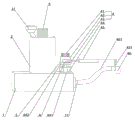
图1为本实用新型立体结构示意图。Fig. 1 is a schematic diagram of the three-dimensional structure of the utility model.
图2为本实用新型剖析结构示意图。Fig. 2 is a schematic diagram of anatomical structure of the utility model.
图3为本实用新型部件A放大示意图。Fig. 3 is an enlarged schematic diagram of component A of the present invention.
其中:1-储料箱;11-出料口;12-第二电机;13-输送杆;2-搅拌箱;21-进料斗;3-第一电机;31-搅拌杆;32-搅拌叶;4-摆动组件,41-正反电机;411-第二转轴;412-第二齿轮;42-摆动箱;421-活动槽;43-摆臂;431-第一转轴;432-第一齿轮;44-第一电动伸缩杆;441-第一固定板;442-第二固定板;45-第二电动伸缩杆;451-固定环;46-出料管;461-出料软管;5-伸缩机构Among them: 1-storage box; 11-discharge port; 12-second motor; 13-conveying rod; 2-stirring box; 21-feeding hopper; 3-first motor; Leaf; 4-swing assembly, 41-positive and negative motor; 411-second shaft; 412-second gear; 42-swing box; 421-movable slot; 43-swing arm; 431-first shaft; 432-first Gear; 44-the first electric telescopic rod; 441-the first fixed plate; 442-the second fixed plate; 45-the second electric telescopic rod; 451-fixed ring; 46-discharge pipe; 461-discharge hose; 5-Telescopic mechanism
具体实施方式Detailed ways
下面结合附图详细说明本实用新型的实施方式。Embodiments of the present utility model will be described in detail below in conjunction with the accompanying drawings.
如图1-3,在本实施列中,一种建筑工程水泥灌注设备,包括,搅拌箱2、储料箱1、伸缩机构5,所述的搅拌箱2设于储料箱1上方,且与储料箱1连通,所述的伸缩机构5设于储料箱1上部位于搅拌箱2一侧。As shown in Figures 1-3, in this embodiment, a construction cement pouring equipment includes a mixing box 2, a material storage box 1, and a
优选的:所述的搅拌箱2顶端靠边连通有一进料斗21,所述的搅拌箱2内设有搅拌杆31,所述的搅拌杆31上焊接有搅拌叶32,且搅拌叶32成上下十字式布设在搅拌杆31上,所述的搅拌箱2顶端中部位置固接有第一电机3,且第一电机3动力输出轴活动穿设于搅拌箱2内与搅拌杆31一端连接。Preferably: the top of the stirring box 2 is connected to a
优选的:所述的储料箱1一侧开设有出料口11,所述的储料箱1内设有输送杆13,且输送杆13远离出料口11的一端连接有第二电机12。Preferably: the side of the storage box 1 is provided with a
优选的:所述的伸缩机构5由第一固定板441、第一电动伸缩杆44、第二固定板442、第二电动伸缩杆45、摆动组件4构成,所述的第一固定板441通过螺栓固接于储料箱1上部,所述的第一电动伸缩杆44为多个,且底座设于第一固定板441上,所述的第一电动伸缩杆44顶端固接有第二固定板442,所述的第二固定板442上固接有摆动组件4,所述的第二电动伸缩杆45连接于摆动组件4中。Preferably: the
优选的:所述的摆动组件4由摆动箱42、摆臂43、正反电机41构成,所述的摆动箱42固接于第二固定板442上,所述的摆动箱42上开设有一个半圆形活动槽421,所述的摆动箱42顶端中部设有正反电机41,且正反电机41的动力输出轴活动穿设于摆动箱42内部,所述的摆臂43通过活动槽421进入摆动箱42内部,所述的摆臂43位于摆动箱42内部端固定套接于第一转轴431上,所述第一转轴431位于摆臂43下方穿设固接有第一齿轮432,所述的第一转轴431上下两端都活动连接于摆动箱42内壁上,所述的第一齿轮432齿合有第二齿轮412,所述的第二齿轮412上穿设固接有第二转轴411,所述的第二转轴411下端活动连接于摆动箱42内壁上,上端与正反电机41的动力输出轴连接,所述的摆臂43远离活动槽421的一端与第二电动伸缩杆45底座固接。Preferably: the swing assembly 4 is composed of a
优选的:所述的第二电动伸缩杆45顶端上套接有一固定环451,所述的固定环451上固接有一出料管46,所述的出料管46一端与所述储料箱1上出料口11通过出料软管461连通。Preferably: the top of the second electric
实施列是这样实施的:The implementation column is implemented like this:
所述的进料斗21将原料送入搅拌箱2内,通过第一电机3带动搅拌杆31的转动,由于搅拌杆31上焊接的搅拌叶32成错位十字布设,因此搅拌中更加均匀,搅拌完成后水泥进入储料箱1,储料箱1内第二电机12带动输送杆13运转,将水泥通过储料箱1上的出料口11送入出料软管461中,沿着出料软管461进入出料管46中,所述的出料管46通过固定环451连接于第二电动伸缩杆45上,所述的第二电动伸缩杆45通过自身的伸缩运作,带动出料管46在模具浇灌时进行前、后移动,所述的第一电动伸缩杆44固定在第一固定板上441上,第一固定板441固定于储料箱1上,使得第一电动伸缩杆44坐落的更稳固,第一电动伸缩杆44通过自身的伸缩运作,带动第二固定板442进行上、下移动,第二固定板442上固接有摆动组件4,所述摆动组件4中的摆臂43与第二电动伸缩杆45底座固接,因此第二电动伸缩杆45可进行向上、向下移动,让出料管46在浇灌模具时可进行向上、向下移动,便于应对各种高度的模具或所需要浇灌的高低程度,所述的第一电动伸缩杆44为多个,在伸缩移动时保证摆动组件4的上、下移动更稳定,使的第二电动伸缩杆45上连接出料管46在浇灌时移动的更稳定,所述的摆动组件4的由正反电机41带动第二转动411运转,第二转轴411带动第二齿轮412运转,第二齿轮带动与之齿合的第一齿轮432运转,第一齿轮432的运转带动第一转轴431运转,第一转动轴431带动套接其上的摆臂43进行运转,通过正反电机41的正反转,实现了摆臂43的向左、向右移动,所述的活动槽421为半圆形一是便于摆臂43的左、右移动,二是限制摆臂43的最大摆动位置为向左、向右各90度,防止转动幅度过大碰撞到设备上造成损坏,上述的运作方式通过外接的控制设备控制,可单一运行或任意组合运行,通过上述的方式完成了设备在对模具进行浇灌时的移动局限性,保证了应对各种模具浇灌时都能保证浇灌的均匀性、保证工作质量的同时、提升了工作效率。The feed hopper 21 feeds the raw materials into the mixing box 2, and the first motor 3 drives the rotation of the
最后应说明的是:以上实施案例仅用以说明本实用新型,而非限制本实用新型所描述的技术方案;因此,尽管本说明书参照上述的各个实施列对本实用新型已进行了详细的说明,但是,本领域的普通技术人员应当理解,仍然可以对本实用新型进行修改或等同替换,而一切不脱离本实用新型的精神和范围的技术方案及其改进,其均应涵盖在本实用新型的权利要求范围中;本实用新型中未详细说明的技术以现有技术实现。Finally, it should be noted that the above examples are only used to illustrate the utility model, rather than limit the technical solution described in the utility model; However, those of ordinary skill in the art should understand that the utility model can still be modified or equivalently replaced, and all technical solutions and improvements that do not depart from the spirit and scope of the utility model should be covered by the rights of the utility model. In the scope of requirements; the technology not specified in the utility model is realized with the prior art.
Claims (4)
Priority Applications (1)
| Application Number | Priority Date | Filing Date | Title |
|---|---|---|---|
| CN202223201077.4U CN219081019U (en) | 2022-12-01 | 2022-12-01 | Building engineering cement filling equipment |
Applications Claiming Priority (1)
| Application Number | Priority Date | Filing Date | Title |
|---|---|---|---|
| CN202223201077.4U CN219081019U (en) | 2022-12-01 | 2022-12-01 | Building engineering cement filling equipment |
Publications (1)
| Publication Number | Publication Date |
|---|---|
| CN219081019U true CN219081019U (en) | 2023-05-26 |
Family
ID=86391931
Family Applications (1)
| Application Number | Title | Priority Date | Filing Date |
|---|---|---|---|
| CN202223201077.4U Expired - Fee Related CN219081019U (en) | 2022-12-01 | 2022-12-01 | Building engineering cement filling equipment |
Country Status (1)
| Country | Link |
|---|---|
| CN (1) | CN219081019U (en) |
Cited By (1)
| Publication number | Priority date | Publication date | Assignee | Title |
|---|---|---|---|---|
| CN117619482A (en) * | 2023-11-29 | 2024-03-01 | 汉方植萃(山东)药业有限公司 | A highland barley peeling device with intelligent screening function |
-
2022
- 2022-12-01 CN CN202223201077.4U patent/CN219081019U/en not_active Expired - Fee Related
Cited By (1)
| Publication number | Priority date | Publication date | Assignee | Title |
|---|---|---|---|---|
| CN117619482A (en) * | 2023-11-29 | 2024-03-01 | 汉方植萃(山东)药业有限公司 | A highland barley peeling device with intelligent screening function |
Similar Documents
| Publication | Publication Date | Title |
|---|---|---|
| CN211541823U (en) | Multistation stirring slip casting machine | |
| CN211762494U (en) | Raw material mixing equipment is used in concrete member production | |
| CN112571620A (en) | Equipment for manufacturing energy-saving heat-insulation concrete hollow building blocks | |
| CN110171056A (en) | A kind of homogeneous fireproof heated board processing unit (plant) | |
| CN208005929U (en) | A kind of constructional ornamental material hollow brick extrusion molding apparatus | |
| CN212467901U (en) | A material mixing device for polyethylene wax production | |
| CN217916106U (en) | Assembled reinforced concrete pouring equipment | |
| CN211415694U (en) | Concrete anti-blocking type agitator tank | |
| CN215540523U (en) | Dry-mixed plastering mortar preparation device | |
| CN213137269U (en) | Stirring and conveying device of brick making machine | |
| CN108381770A (en) | A kind of adjustable mixing plant of feed rate applied to concrete uniform stirring | |
| CN116852537A (en) | Concrete proportioning device and using method thereof | |
| CN115788096A (en) | Civil construction engineering structure gap grouting equipment | |
| CN108261958A (en) | A kind of automatic glue mixing device | |
| CN213617501U (en) | Processing device for partition board raw materials | |
| CN214764871U (en) | Automatic casting machine | |
| CN222406435U (en) | Mortar stirring device | |
| CN218712234U (en) | A bridge head grouting machine | |
| CN219043997U (en) | A cement raw material uniform batching device | |
| CN217670163U (en) | A kind of cement mixing device for water conservancy project construction | |
| CN222521660U (en) | Raw material mixing device for producing prefabricated locking bricks | |
| CN219951831U (en) | Hydraulic engineering maintenance fastening treatment mechanism | |
| CN222730546U (en) | Grouting device for hydraulic engineering construction | |
| CN222972479U (en) | Cement slurry preparation device for high-pressure jet grouting pile construction | |
| CN220179735U (en) | Automatic batching machine for concrete mixing plant |
Legal Events
| Date | Code | Title | Description |
|---|---|---|---|
| GR01 | Patent grant | ||
| GR01 | Patent grant | ||
| CF01 | Termination of patent right due to non-payment of annual fee | ||
| CF01 | Termination of patent right due to non-payment of annual fee |
Granted publication date: 20230526 |