CN219075370U - A shot blasting machine with a dust removal device - Google Patents
A shot blasting machine with a dust removal device Download PDFInfo
- Publication number
- CN219075370U CN219075370U CN202222992827.8U CN202222992827U CN219075370U CN 219075370 U CN219075370 U CN 219075370U CN 202222992827 U CN202222992827 U CN 202222992827U CN 219075370 U CN219075370 U CN 219075370U
- Authority
- CN
- China
- Prior art keywords
- dust
- pipe
- shot blasting
- blasting machine
- box body
- Prior art date
- Legal status (The legal status is an assumption and is not a legal conclusion. Google has not performed a legal analysis and makes no representation as to the accuracy of the status listed.)
- Expired - Fee Related
Links
Images

Classifications
-
- Y—GENERAL TAGGING OF NEW TECHNOLOGICAL DEVELOPMENTS; GENERAL TAGGING OF CROSS-SECTIONAL TECHNOLOGIES SPANNING OVER SEVERAL SECTIONS OF THE IPC; TECHNICAL SUBJECTS COVERED BY FORMER USPC CROSS-REFERENCE ART COLLECTIONS [XRACs] AND DIGESTS
- Y02—TECHNOLOGIES OR APPLICATIONS FOR MITIGATION OR ADAPTATION AGAINST CLIMATE CHANGE
- Y02P—CLIMATE CHANGE MITIGATION TECHNOLOGIES IN THE PRODUCTION OR PROCESSING OF GOODS
- Y02P70/00—Climate change mitigation technologies in the production process for final industrial or consumer products
- Y02P70/10—Greenhouse gas [GHG] capture, material saving, heat recovery or other energy efficient measures, e.g. motor control, characterised by manufacturing processes, e.g. for rolling metal or metal working
Landscapes
- Filtering Of Dispersed Particles In Gases (AREA)
Abstract
Description
技术领域technical field
本实用新型涉及抛丸机技术领域,尤其涉及一种带有除尘装置的抛丸机。The utility model relates to the technical field of shot blasting machines, in particular to a shot blasting machine with a dust removal device.
背景技术Background technique
抛丸机利用抛丸器抛出的高速弹丸清理或强化铸件表面的铸造设备,在对铸件表面进行抛丸时,会产生大量的灰尘,如果不对灰尘进行处理,会造成环境造成污染,不利于车间的工作环境,会损害工人的健康。The shot blasting machine uses the high-speed projectile thrown by the shot blaster to clean or strengthen the casting equipment on the surface of the casting. When the surface of the casting is shot blasted, a large amount of dust will be generated. If the dust is not treated, it will cause environmental pollution, which is not conducive to The working environment in the workshop will damage the health of workers.
申请号为CN202120730341.X的中国专利公开了一种铸件表面清理用抛丸机,包括固定底座,所述固定底座的上端固定连接有箱体,所述箱体的两个内侧壁之间共同固定连接有板网,所述板网的上端设置有铸件,所述板网的上端与箱体的内顶部之间共同固定连接有两个对称设置的固定杆,两个所述固定杆上均设置有用于对铸件进行固定的固定机构,所述箱体的一端内侧壁上开设有滑槽,所述滑槽的内部设置有用于对弹丸进行下料的下料机构,所述箱体的内部设置有用于对下料机构进行驱动的驱动机构,所述固定底座的上端还设置有用于对箱体内进行除尘的除尘机构;所述除尘机构包括固定连接在固定底座上端的吸尘器,所述吸尘器的一端固定连接有进气管,所述进气管穿过箱体的侧壁,所述吸尘器的上端设置有出气管;该技术方案中通过吸尘器将灰尘吸出,未对灰尘进行处理就直接将灰尘进行排放,如果灰尘没有经过专业的设备进行处理,还会污染其他地方的环境,没有从根本上解决环境污染的问题。The Chinese patent application number CN202120730341.X discloses a shot blasting machine for casting surface cleaning, including a fixed base, the upper end of the fixed base is fixedly connected with a box, and the two inner side walls of the box are jointly fixed An expanded net is connected, and the upper end of the expanded expanded net is provided with a casting, and two symmetrically arranged fixing rods are fixedly connected between the upper end of the expanded expanded net and the inner top of the box body, and two fixed rods are provided with There is a fixing mechanism for fixing the castings, a chute is provided on the inner wall of one end of the box, and a blanking mechanism for unloading the projectiles is arranged inside the chute, and the inside of the box is set There is a driving mechanism for driving the unloading mechanism, and the upper end of the fixed base is also provided with a dust removal mechanism for removing dust in the box; the dust removal mechanism includes a vacuum cleaner fixedly connected to the upper end of the fixed base, and one end of the vacuum cleaner An air intake pipe is fixedly connected, the air intake pipe passes through the side wall of the box body, and an air outlet pipe is provided at the upper end of the vacuum cleaner; in this technical solution, the dust is sucked out by the vacuum cleaner, and the dust is directly discharged without processing the dust. If the dust is not processed by professional equipment, it will also pollute the environment in other places, and the problem of environmental pollution has not been fundamentally solved.
实用新型内容Utility model content
本实用新型的目的是提供一种带有除尘装置的抛丸机,解决现有技术中抛丸机除尘机构通过吸尘器将灰尘吸出,未对灰尘进行处理就直接将灰尘进行排放,虽然改善了车间环境,但是还会污染其他地方环境的问题。The purpose of this utility model is to provide a shot blasting machine with a dust removal device, which solves the problem that in the prior art, the dust removal mechanism of the shot blasting machine sucks out the dust through a vacuum cleaner, and directly discharges the dust without processing the dust. environment, but it will also pollute the environment of other places.
为解决上述技术问题,本实用新型采用如下技术方案:In order to solve the above technical problems, the utility model adopts the following technical solutions:
本实用新型一种带有除尘装置的抛丸机,包括箱体,所述箱体的底部设置有支撑腿,所述箱体的内部设置有隔板,所述隔板将所述箱体分为工作腔和除尘腔,所述工作腔的正面铰接有第一箱门,所述除尘腔的正面铰接有第二箱门,所述工作腔的内部设置有抛丸器,所述抛丸器的下方设置有板网,所述板网的顶面设置有放置座,所述工作腔的外侧设置有皮带提升机,所述皮带提升机的一端与所述工作腔连通,所述皮带提升机的另一端与所述抛丸器的进丸口连通;还包括除尘装置,所述除尘装置包括吸尘组件,所述吸尘组件包括设置在所述工作腔内部的连接管,所述连接管上均匀设置有若干吸尘管,所述连接管通过导灰管与吸风机连通,所述吸风机的出口端与所述除尘腔连通,所述除尘腔的内部设置有加湿组件,所述吸风机的出口端位于所述加湿组件的下方,所述加湿组件的上方依次设置有过滤网和吸附层,所述除尘腔的侧壁上且位于所述吸附层的上方设置有出气管,所述除尘腔的底部设置有排污管。The utility model is a shot blasting machine with a dust removal device, which includes a box body, the bottom of the box body is provided with supporting legs, and the inside of the box body is provided with partitions, and the partition board divides the box body into two parts. It is a working chamber and a dust removal chamber, the front of the working chamber is hinged with a first door, the front of the dust removal chamber is hinged with a second door, the inside of the working chamber is provided with a shot blaster, and the shot blaster The bottom of the expanse is provided with an expanse, the top surface of the expanse is provided with a placement seat, the outside of the working chamber is provided with a belt hoist, one end of the belt hoist communicates with the working chamber, and the belt hoist The other end of the shot blasting machine communicates with the shot inlet; it also includes a dust removal device, the dust removal device includes a dust suction assembly, and the dust suction assembly includes a connecting pipe arranged inside the working chamber, and the connecting pipe A number of dust suction pipes are evenly arranged on the top, the connecting pipe communicates with the suction fan through the ash guide pipe, the outlet end of the suction fan communicates with the dust removal chamber, and a humidifying component is arranged inside the dust removal chamber. The outlet end of the fan is located below the humidification assembly, and a filter screen and an adsorption layer are sequentially arranged above the humidification assembly, and an air outlet pipe is arranged on the side wall of the dust removal chamber and above the adsorption layer. The bottom of the dust removal chamber is provided with a sewage pipe.
进一步的,所述隔板倾斜布置,所述隔板的最低位置与所述皮带提升机的进口端连通。Further, the baffle is arranged obliquely, and the lowest position of the baffle communicates with the inlet end of the belt elevator.
再进一步的,所述除尘腔的外侧焊接有支撑板,所述吸风机安装在所述支撑板上。Still further, a support plate is welded on the outside of the dust removal chamber, and the suction fan is installed on the support plate.
再进一步的,所述加湿组件包括水箱,所述水箱通过螺栓连接在所述箱体的顶面,所述水箱的顶面通过支架安装有水泵,所述水泵上连接有水管,所述水管上安装有阀门,所述水管的另一端延伸至所述除尘腔内部,位于所述除尘腔内的所述水管上等间距布置有多个雾化喷头,所述吸风机的出口端位于所述雾化喷头的下方,所述雾化喷头的上方依次设置有所述过滤网和所述吸附层。Still further, the humidification assembly includes a water tank, the water tank is connected to the top surface of the box body through bolts, a water pump is installed on the top surface of the water tank through a bracket, and a water pipe is connected to the water pump. A valve is installed, the other end of the water pipe extends to the inside of the dust removal chamber, a plurality of atomizing nozzles are arranged at equal intervals on the water pipe in the dust removal chamber, and the outlet end of the suction fan is located in the dust removal chamber. Below the atomization spray head, the filter screen and the adsorption layer are sequentially arranged above the atomization spray head.
再进一步的,所述吸尘管的外侧套设有防护网,所述防护网通过螺栓连接在所述工作腔的内壁上,所述防护网的孔径小于弹丸的直径。Still further, the outer side of the dust suction pipe is covered with a protective net, the protective net is connected to the inner wall of the working chamber by bolts, and the aperture of the protective net is smaller than the diameter of the projectile.
再进一步的,所述板网上网孔的直径大于弹丸的直径。Still further, the diameter of the mesh holes on the plate net is larger than the diameter of the projectile.
再进一步的,所述支撑腿的底部安装有福马轮。Still further, a Fuma wheel is installed on the bottom of the supporting legs.
与现有技术相比,本实用新型的有益技术效果:Compared with the prior art, the utility model has the beneficial technical effect:
本实用新型一种带有除尘装置的抛丸机,通过加湿组件对灰尘进行淋湿,使得粉尘与空气分离,空气依次通过过滤网和吸附层进行过滤和活性炭吸附,净化后的空气通过出气管排出,不会再次污染环境,灰尘通过排污管排出,便于对灰尘进行收集处理,避免环境污染;抛丸机自带除尘装置,不需要单独购买空气净化设备,节约了生产成本。The utility model is a shot blasting machine with a dust removal device. The dust is wetted by a humidifying component, so that the dust is separated from the air. The air is filtered and adsorbed by activated carbon through the filter screen and the adsorption layer in turn, and the purified air passes through the air outlet pipe. Discharge will not pollute the environment again. The dust is discharged through the sewage pipe, which is convenient for collecting and processing the dust and avoiding environmental pollution; the shot blasting machine comes with a dust removal device, and there is no need to purchase air purification equipment separately, which saves production costs.
附图说明Description of drawings
下面结合附图说明对本实用新型作进一步说明。The utility model will be further described below in conjunction with the accompanying drawings.
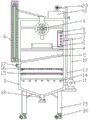
图1为本实用新型带有除尘装置的抛丸机内部结构示意图;Fig. 1 is a schematic diagram of the internal structure of the shot blasting machine with dust removal device of the present invention;
图2为本实用新型带有除尘装置的抛丸机主视图;Fig. 2 is the front view of the shot blasting machine with dust removal device of the present invention;
附图标记说明:1、箱体;2、隔板;3、抛丸器;4、板网;5、放置座;6、皮带提升机;7、连接管;8、吸尘管;9、防护网;10、导灰管;11、吸风机;12、水箱;13、水管;14、雾化喷头;15、过滤网;16、吸附层;17、出气管;18、排污管;19、支撑腿;20、福马轮;21、第一箱门;22、第二箱门;23、水泵。Explanation of reference signs: 1. Box body; 2. Partition plate; 3. Shot blasting device; 4. Plate net; 5. Placement seat; 6. Belt hoist; 7. Connecting pipe; Protective net; 10, ash guide pipe; 11, suction fan; 12, water tank; 13, water pipe; 14, atomizing nozzle; 15, filter screen; 16, adsorption layer; 17, air outlet pipe; 18, sewage pipe; 19, Supporting leg; 20, Fuma wheel; 21, first box door; 22, second box door; 23, water pump.
具体实施方式Detailed ways
为了使本实用新型所要解决的技术问题、技术方案及有益效果更加清楚明白,以下结合附图及实施例,对本实用新型进行进一步详细说明。应当理解,此处所描述的具体实施例仅用以解释本实用新型,并不用于限定本实用新型。需要说明的是,术语“第一”、“第二”仅用于描述目的,而不能理解为指示或暗示相对重要性或者隐含指明所指示的技术特征的数量。由此,限定有“第一”、“第二”的特征可以明示或者隐含地包括一个或者更多个该特征。在本实用新型的描述中,“多个”的含义是两个或两个以上,除非另有明确具体的限定。“若干”的含义是一个或一个以上,除非另有明确具体的限定。In order to make the technical problems, technical solutions and beneficial effects to be solved by the utility model clearer, the utility model will be further described in detail below in conjunction with the accompanying drawings and embodiments. It should be understood that the specific embodiments described here are only used to explain the utility model, and are not intended to limit the utility model. It should be noted that the terms "first" and "second" are only used for descriptive purposes, and cannot be understood as indicating or implying relative importance or implicitly indicating the quantity of indicated technical features. Thus, a feature defined as "first" and "second" may explicitly or implicitly include one or more of these features. In the description of the present utility model, "plurality" means two or more, unless otherwise specifically defined. "Several" means one or more than one, unless otherwise clearly and specifically defined.
在本实用新型的描述中,需要理解的是,术语“上”、“下”、“前”、“后”、“左”、“右”等指示的方位或位置关系为基于附图所示的方位或位置关系,仅是为了便于描述本实用新型和简化描述,而不是指示或暗示所指的装置或元件必须具有特定的方位、以特定的方位构造和操作,因此不能理解为对本实用新型的限制。In the description of the present utility model, it should be understood that the orientation or positional relationship indicated by the terms "upper", "lower", "front", "rear", "left", "right" etc. The orientation or positional relationship is only for the convenience of describing the utility model and simplifying the description, but does not indicate or imply that the device or element referred to must have a specific orientation, be constructed and operated in a specific orientation, so it cannot be understood as a reference to the utility model. limits.
如图1-2所示,一种带有除尘装置的抛丸机,包括箱体1,所述箱体1的底部焊接有支撑腿19,所述箱体1的内部焊接有隔板2,所述隔板2将所述箱体1分为工作腔和除尘腔,所述工作腔的正面铰接有第一箱门21,所述除尘腔的正面铰接有第二箱门22,所述工作腔的内部设置有抛丸器3,所述抛丸器3的下方设置有板网4,板网4通过螺栓连接在工作腔的内壁上,所述板网4的顶面通过螺栓连接有放置座5,所述工作腔的外侧安装有皮带提升机6,所述皮带提升机6的一端与所述工作腔连通,所述皮带提升机6的另一端与所述抛丸器3的进丸口连通;还包括除尘装置,所述除尘装置包括吸尘组件,所述吸尘组件包括设置在所述工作腔内部的连接管7,所述连接管7上均匀设置有若干吸尘管8,所述连接管7通过导灰管10与吸风机11连通,所述吸风机11的出口端与所述除尘腔连通;所述除尘腔的内部设置有加湿组件,所述加湿组件的上方依次设置有过滤网15和吸附层16,所述除尘腔的侧壁上且位于所述吸附层16的上方设置有出气管17,所述除尘腔的底部设置有排污管18,所述吸风机11的出口端位于所述加湿组件的下方。As shown in Figure 1-2, a shot blasting machine with a dust removal device includes a
具体的,工作腔的两侧内壁上对称连接有连接杆,两个连接杆相对的一端连接有抛丸器3,抛丸器3通过外部电源进行供电,抛丸器3上端连通有进丸口,且进丸口延伸出箱体1,抛丸器3下端连通设置有出丸口,出丸口位于放置座5的正上方,所述板网4上网孔的直径大于弹丸的直径;使用时,将铸件放置到放置座5上,抛丸器3抛出弹丸对铸件表面进行清理,之后弹丸落到板网4上并通过板网4的通孔掉落到隔板2上;所述隔板2倾斜布置,所述隔板2的最低位置与所述皮带提升机6的进口端连通,弹丸沿隔板2下滑并进入皮带提升机6,通过皮带提升机6提升,再经过皮带提升机6出口端的输送管重新输送至抛丸器3上端的进丸口。Specifically, connecting rods are symmetrically connected to the inner walls on both sides of the working chamber, and the opposite ends of the two connecting rods are connected to a shot blasting device 3, which is powered by an external power supply, and the upper end of the blasting device 3 is connected to a shot inlet. , and the shot inlet extends out of the
所述除尘腔的外侧焊接有支撑板,所述吸风机11安装在所述支撑板上。A support plate is welded on the outside of the dust removal chamber, and the
所述加湿组件包括水箱12,所述水箱12通过螺栓连接在所述箱体1的顶面,所述水箱12的顶面通过支架安装有水泵23,所述水泵23上连接有水管13,所述水管13上安装有阀门,所述水管13的另一端延伸至所述除尘腔内部,位于所述除尘腔内的所述水管13上等间距布置有多个雾化喷头14,所述吸风机11的出口端位于所述雾化喷头14的下方,所述雾化喷头14的上方依次设置有所述过滤网15和所述吸附层16;具体的,除尘腔的内壁上通过螺栓连接有支撑块,过滤网15和吸附层16放置在支撑块上,便于拆卸、更换;吸附层16为活性炭层,不仅能够对空气中粉尘进行吸附,还能达到净化空气的效果。The humidification assembly includes a water tank 12, the water tank 12 is connected to the top surface of the
所述吸尘管8的外侧套设有防护网9,所述防护网9通过螺栓连接在所述工作腔的内壁上,所述防护网9的孔径小于弹丸的直径;防护网9可以保护吸尘管8,防止弹丸砸坏吸尘管8。The outer side of the dust suction pipe 8 is covered with a protective net 9, the protective net 9 is connected to the inner wall of the working chamber by bolts, the aperture of the protective net 9 is smaller than the diameter of the projectile; the protective net 9 can protect the suction Dust pipe 8 prevents projectile from smashing dust suction pipe 8.
为了便于装置的移动和转运,所述支撑腿19的底部安装有福马轮20。In order to facilitate the movement and transfer of the device, the bottom of the
本实用新型的工作过程如下:The working process of the present utility model is as follows:
首先,将铸件放置到放置座5上,启动抛丸器3,抛丸器3抛出弹丸对铸件表面进行清理,弹丸落到板网4上会沿板网4的通孔掉落到隔板2上,弹丸沿隔板2下滑,进入皮带提升机6,通过皮带提升机6提升,经过皮带提升机6出口端的输送管重新输送至抛丸器3上端的进丸口。First, place the casting on the
对铸件表面清理过程中启动吸风机11,吸风机11将工作腔内的灰尘吸入到除尘腔内,通过打开阀门,启动水泵23,水泵23将水箱12中的水导入水管13,由雾化喷头14喷出,对灰尘进行淋湿,使得粉尘与空气分离,空气依次通过过滤网15和吸附层16进行过滤和活性炭吸附,最后通过出气管17排出,灰尘通过排污管18排出。Start the
本实用新型中涉及的抛丸器、吸风机、福马轮、水泵等均属于现有技术,购买后组装到相应位置即可,在此不再赘述。The shot blaster, suction fan, Foma wheel, water pump, etc. involved in the utility model all belong to the prior art, and they can be assembled to the corresponding positions after purchase, and will not be repeated here.
以上所述的实施例仅是对本实用新型的优选方式进行描述,并非对本实用新型的范围进行限定,在不脱离本实用新型设计精神的前提下,本领域普通技术人员对本实用新型的技术方案做出的各种变形和改进,均应落入本实用新型权利要求书确定的保护范围内。The above-mentioned embodiment is only to describe the preferred mode of the present utility model, not to limit the scope of the present utility model. The various deformations and improvements mentioned above should all fall within the scope of protection determined by the claims of the present utility model.
Claims (7)
Priority Applications (1)
| Application Number | Priority Date | Filing Date | Title |
|---|---|---|---|
| CN202222992827.8U CN219075370U (en) | 2022-11-10 | 2022-11-10 | A shot blasting machine with a dust removal device |
Applications Claiming Priority (1)
| Application Number | Priority Date | Filing Date | Title |
|---|---|---|---|
| CN202222992827.8U CN219075370U (en) | 2022-11-10 | 2022-11-10 | A shot blasting machine with a dust removal device |
Publications (1)
| Publication Number | Publication Date |
|---|---|
| CN219075370U true CN219075370U (en) | 2023-05-26 |
Family
ID=86406422
Family Applications (1)
| Application Number | Title | Priority Date | Filing Date |
|---|---|---|---|
| CN202222992827.8U Expired - Fee Related CN219075370U (en) | 2022-11-10 | 2022-11-10 | A shot blasting machine with a dust removal device |
Country Status (1)
| Country | Link |
|---|---|
| CN (1) | CN219075370U (en) |
-
2022
- 2022-11-10 CN CN202222992827.8U patent/CN219075370U/en not_active Expired - Fee Related
Similar Documents
| Publication | Publication Date | Title |
|---|---|---|
| CN109395518A (en) | Soot processing device is used in a kind of granulation of metal | |
| CN105818001A (en) | Integrated grinding and polishing dust collector | |
| CN111229769A (en) | A dust removal device for a mask processing workshop | |
| CN207012698U (en) | A kind of dust collector of shot blasting machine | |
| CN205888903U (en) | Integrated grinding and polishing dust collector | |
| CN202701956U (en) | Water curtain type integral polishing and dedusting operating platform | |
| CN210699243U (en) | Polishing and purifying workshop | |
| CN209221755U (en) | A kind of dust-extraction unit of antenna cover | |
| CN219252063U (en) | A dust removal and cooling device for bio-organic fertilizer production | |
| CN222765948U (en) | A dust removal device for organic fertilizer processing | |
| CN116638860A (en) | A flat die-cutting bronzing machine dust removal device | |
| CN216912003U (en) | Smelting furnace for high-temperature alloy forging | |
| CN219494870U (en) | Dust collector of smelting furnace | |
| CN220860966U (en) | Novel dust removal device | |
| CN209440005U (en) | A kind of automatic sand-blasting machine convenient for heat dissipation | |
| CN216935097U (en) | Portable industrial dust shaker of modularization | |
| CN222511694U (en) | A weeder blade sandblasting device | |
| CN219685126U (en) | Dust removing device of shot blasting machine | |
| CN219539850U (en) | Workshop water spray type dust remover with ultra-clean emission | |
| CN223700492U (en) | A dust removal device for grinding wheels | |
| CN219897547U (en) | Dust removing device for nonferrous metal mining | |
| CN223887693U (en) | A mobile exhaust gas purification and treatment unit | |
| CN223930997U (en) | A boiler flue gas recovery and dust settling mechanism | |
| CN220944695U (en) | Aluminum product surface treatment device | |
| CN219072360U (en) | An air filter dust removal device |
Legal Events
| Date | Code | Title | Description |
|---|---|---|---|
| GR01 | Patent grant | ||
| GR01 | Patent grant | ||
| CF01 | Termination of patent right due to non-payment of annual fee |
Granted publication date: 20230526 |
|
| CF01 | Termination of patent right due to non-payment of annual fee |