CN219073236U - Environment-friendly equipment belt cleaning device - Google Patents
Environment-friendly equipment belt cleaning device Download PDFInfo
- Publication number
- CN219073236U CN219073236U CN202320083569.3U CN202320083569U CN219073236U CN 219073236 U CN219073236 U CN 219073236U CN 202320083569 U CN202320083569 U CN 202320083569U CN 219073236 U CN219073236 U CN 219073236U
- Authority
- CN
- China
- Prior art keywords
- water
- spray
- cleaning device
- environmental protection
- supply pipe
- Prior art date
- Legal status (The legal status is an assumption and is not a legal conclusion. Google has not performed a legal analysis and makes no representation as to the accuracy of the status listed.)
- Active
Links
Images
Landscapes
- Separation Of Particles Using Liquids (AREA)
Abstract
本实用新型公开了一种环保设备清洗装置,涉及环保净化设备技术领域,包括设备本体和喷淋组件,设备本体的下部设置有进风箱体和出风箱体,所述设备本体下部的一侧设置有喷淋组件,喷淋组件设置有热水箱和送水管,所述送水管的上端连接有喷淋支架通过进水口进入高温水,水温最好是80‑100度左右,通过抽水机把热水往送水管输送,送水管连接通水管道,通过通水管道把热水送到喷淋支架,然后从喷淋嘴喷出,喷淋嘴是可以调节出水的模式的,可以是雾化的也可以是喷出水雾的,通过喷淋嘴喷出的高温水淋到下面的电离净化器的管子里面去,这样管子里面的内部的灰尘和油污通过高温水清洗干净,这样就不需要进行拆解机器来清洗,方便又实用。

The utility model discloses an environmental protection equipment cleaning device, which relates to the technical field of environmental protection purification equipment, and comprises an equipment body and a spray assembly. The lower part of the equipment body is provided with an air inlet box and an air outlet box. There is a spray assembly on the side, and the spray assembly is provided with a hot water tank and a water supply pipe. The upper end of the water supply pipe is connected with a spray bracket and enters high-temperature water through the water inlet. The water temperature is preferably about 80‑100 degrees. The hot water is sent to the water supply pipe, the water supply pipe is connected to the water pipe, and the hot water is sent to the spray bracket through the water pipe, and then sprayed from the spray nozzle. The spray nozzle can adjust the water outlet mode, which can be atomized It can also be sprayed with water mist. The high-temperature water sprayed from the spray nozzle is poured into the tube of the ionization purifier below, so that the internal dust and oil in the tube are cleaned by high-temperature water, so that there is no need to It is convenient and practical to disassemble the machine for cleaning.
Description
技术领域technical field
本实用新型涉及环保净化设备技术领域,具体为一种环保设备清洗装置。The utility model relates to the technical field of environmental protection purification equipment, in particular to an environmental protection equipment cleaning device.
背景技术Background technique
目前烟雾粉尘净化设备已经很普及了,但是这些设备使用久了之后会残留有粉尘和油污,这些都是在电离设备的管壁上,要清洗是很麻烦的,需要拆开机器来清洁,而且还要再次进行装配,这样太麻烦了,费时又费力,有这样的问题,我们可不可以通过不需要拆解机器就可以进行清洗了,为此我们设计出一种环保设备清洗装置。At present, smog and dust purification equipment is very popular, but these equipment will remain dust and oil stains after a long time of use, these are all on the tube wall of the ionization equipment, it is very troublesome to clean, you need to disassemble the machine to clean, and It needs to be assembled again, which is too troublesome, time-consuming and labor-intensive. If there is such a problem, can we clean it without dismantling the machine, so we have designed an environmental protection equipment cleaning device.
实用新型内容Utility model content
针对现有技术的不足,本实用新型提供了一种环保设备清洗装置,解决了目前烟气净化器在长期使用中,内表面会粘附油分子以及其他杂质,因此需要定期对烟气净化器内部进行清理,由于对烟气净化器内部通常采用人工的方式进行清理,效率较慢,从而影响烟气净化器的使用的问题。Aiming at the deficiencies of the prior art, the utility model provides a cleaning device for environmental protection equipment, which solves the problem that oil molecules and other impurities will adhere to the inner surface of the current flue gas purifier during long-term use, so it is necessary to regularly clean the flue gas purifier. Internal cleaning, because the inside of the flue gas purifier is usually cleaned manually, the efficiency is slow, which affects the use of the flue gas purifier.
为实现以上目的,本实用新型通过以下技术方案予以实现:一种环保设备清洗装置,包括设备本体和喷淋组件,所述设备本体的下部设置有进风箱体和出风箱体,所述设备本体下部的一侧设置有喷淋组件,所述喷淋组件设置有热水箱和送水管,所述送水管的上端连接有喷淋支架。In order to achieve the above objectives, the utility model is achieved through the following technical solutions: an environmental protection equipment cleaning device, including a device body and a spray assembly, the lower part of the device body is provided with an air inlet box and an air outlet box, the One side of the lower part of the device body is provided with a spray assembly, the spray assembly is provided with a hot water tank and a water delivery pipe, and the upper end of the water delivery pipe is connected with a spray bracket.
优选地;所述喷淋组件包括抽水机,所述热水箱的一侧设置有进水口,所述抽水机与送水管相连接。Preferably; the spray assembly includes a water pump, a water inlet is provided on one side of the hot water tank, and the water pump is connected to a water delivery pipe.
优选地;所述喷淋支架的一端通水管道,所述通水管道与喷淋支架为中空结构,所述喷淋支架的下部设置若干喷淋嘴。Preferably; one end of the spray bracket has a water pipe, the water pipe and the spray bracket are hollow structures, and several spray nozzles are arranged at the lower part of the spray bracket.
优选地;所述进风箱体内部设置有凹槽容腔,所述凹槽容腔中部设置有流水通孔,所述流水通孔连接有排排废水管道。Preferably, a groove cavity is provided inside the air inlet box, and a water flow hole is arranged in the middle of the groove cavity, and the water flow hole is connected to a drainage waste water pipe.
优选地;所述喷淋嘴通过通水管道灌入高温水,使其喷出高温蒸汽或水花。Preferably; the spray nozzle is filled with high-temperature water through the water pipe to make it spray high-temperature steam or spray.
优选地;所述设备本体的中间内部设置有电离净化器,所述电离净化器为管状物,所述电离净化器的上部固定设置有喷淋支架,所述喷淋支架喷出的高温水雾给电离净化器清洁。Preferably; an ionization purifier is provided in the middle of the device body, the ionization purifier is a tubular object, and the upper part of the ionization purifier is fixed with a spray bracket, and the high-temperature water mist sprayed by the spray bracket Clean the ionizer.
有益效果Beneficial effect
本实用新型提供了一种环保设备清洗装置。与现有技术相比具备以下有益效果:The utility model provides an environmental protection equipment cleaning device. Compared with the prior art, it has the following beneficial effects:
一清洗工作,通过进水口进入高温水(外置),水温最好是80-100度左右,通过抽水机把热水往送水管输送,送水管连接通水管道,通过通水管道把热水送到喷淋支架,然后从喷淋嘴喷出,喷淋嘴是可以调节出水的模式的,可以是雾化的也可以是喷出水雾的,这个是现有的产品,通过喷淋嘴喷出的高温水淋到下面的电离净化器的管子里面去,这样管子里面的内部的灰尘和油污通过高温水清洗干净,由于是立式结构在水的重力下一直往下滴落,然后落到凹槽容腔的内部,然后在通过流水通孔连接排水管流到指定的地方去,完成清洗过程,这样就不需要进行拆解机器来清洗,方便又实用。After cleaning, enter the high-temperature water (external) through the water inlet. The water temperature is preferably about 80-100 degrees. The hot water is sent to the water supply pipe through the water pump, and the water supply pipe is connected to the water pipe, and the hot water is sent through the water pipe. to the spray bracket, and then spray from the spray nozzle. The spray nozzle can adjust the water outlet mode, which can be atomized or spray water mist. This is an existing product, sprayed through the spray nozzle The high-temperature water that comes out is poured into the tube of the ionization purifier below, so that the dust and oil stains inside the tube are cleaned by high-temperature water, and because it is a vertical structure, it drips down under the gravity of the water, and then falls to the The inside of the groove cavity is then connected to the designated place through the water through hole to complete the cleaning process, so that there is no need to disassemble the machine for cleaning, which is convenient and practical.
附图说明Description of drawings
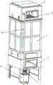
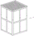
图1为一种环保设备清洗装置的整体示意图;Fig. 1 is the overall schematic diagram of a kind of environmental protection equipment cleaning device;
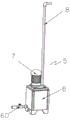
图2为一种环保设备清洗装置的喷淋组件结构示意图;Fig. 2 is a schematic structural diagram of a spray assembly of an environmental protection equipment cleaning device;
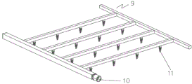
图3为一种环保设备清洗装置的阳喷淋支架示意图;Fig. 3 is a schematic diagram of a positive spray bracket of an environmental protection equipment cleaning device;
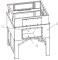
图4为一种环保设备清洗装置的进风箱体结构示意图;Fig. 4 is a structural schematic diagram of an air inlet box of an environmental protection equipment cleaning device;
图5为一种环保设备清洗装置的电离净化器示意图。Fig. 5 is a schematic diagram of an ionization purifier of an environmental protection equipment cleaning device.
图中:1、设备本体;2、进风箱体;3出风箱体;4、电离净化器;5、喷淋组件;6热水箱;60进水口;7抽水机;8送水管,9喷淋支架;10通水管道,11喷淋嘴,12凹槽容腔,13流水通孔。In the figure: 1. Equipment body; 2. Air inlet box; 3 Air outlet box; 4. Ionization purifier; 5. Spray assembly; 6. Hot water tank; 60 Water inlet; Spray bracket; 10 water pipes, 11 spray nozzles, 12 groove cavity, 13 water through holes.
具体实施方式Detailed ways
下面将结合本实用新型实施例中的附图,对本实用新型实施例中的技术方案进行清楚、完整地描述,显然,所描述的实施例仅仅是本实用新型一部分实施例,而不是全部的实施例。基于本实用新型中的实施例,本领域普通技术人员在没有做出创造性劳动前提下所获得的所有其他实施例,都属于本实用新型保护的范围。The technical solutions in the embodiments of the present invention will be clearly and completely described below in conjunction with the accompanying drawings in the embodiments of the present invention. Obviously, the described embodiments are only part of the embodiments of the present invention, not all of them. example. Based on the embodiments of the present utility model, all other embodiments obtained by persons of ordinary skill in the art without making creative efforts belong to the scope of protection of the present utility model.
请参阅图1-5,一种环保设备清洗装置,包括设备本体1和喷淋组件5,所述设备本体1的下部设置有进风箱体2和出风箱体3,其特征在于;所述设备本体1下部的一侧设置有喷淋组件5,所述喷淋组件5设置有热水箱6和送水管8,所述送水管8的上端连接有喷淋支架9,所述喷淋组件5包括抽水机7,所述热水箱6的一侧设置有进水口60,所述抽水机7与送水管8相连接,喷淋支架9的一端通水管道10,所述通水管道10与喷淋支架9为中空结构,所述喷淋支架9的下部设置若干喷淋嘴11,进风箱体2内部设置有凹槽容腔12,所述凹槽容腔中部设置有流水通孔13,所述流水通孔13连接有排排废水管道,喷淋嘴11通过通水管道10灌入高温水,使其喷出高温蒸汽或水花,设备本体1的中间内部设置有电离净化器4,所述电离净化器4为管状物,所述电离净化器4的上部固定设置有喷淋支架9,所述喷淋支架9喷出的高温水雾给电离净化器4清洁。Please refer to Figures 1-5, a cleaning device for environmental protection equipment, including a device body 1 and a spray assembly 5, the lower part of the device body 1 is provided with an
本实用新型的工作原理:首先把设备本体1按照好,通过生产场地的管道连接到进风箱体2,然后在从出风箱体3排出处理过的烟雾气体,在设置处理完毕后停止净化工作,然后开始清洗工作,通过进水口60进入高温水(外置),水温最好是80-100度左右,通过抽水机7把热水往送水管8输送,送水管8连接通水管道10,通过通水管道10把热水送到喷淋支架9,然后从喷淋嘴11喷出,喷淋嘴11是可以调节出水的模式的,可以是雾化的也可以是喷出水雾的,这个是现有的产品,通过喷淋嘴喷出的高温水淋到下面的电离净化器的管子里面去,这样管子里面的内部的灰尘和油污通过高温水清洗干净,由于是立式结构在水的重力下一直往下滴落,然后落到凹槽容腔12的内部,然后在通过流水通孔13连接排水管流到指定的地方去,完成清洗过程。The working principle of the utility model: first, the device body 1 is connected to the
Claims (6)
Priority Applications (1)
| Application Number | Priority Date | Filing Date | Title |
|---|---|---|---|
| CN202320083569.3U CN219073236U (en) | 2023-01-29 | 2023-01-29 | Environment-friendly equipment belt cleaning device |
Applications Claiming Priority (1)
| Application Number | Priority Date | Filing Date | Title |
|---|---|---|---|
| CN202320083569.3U CN219073236U (en) | 2023-01-29 | 2023-01-29 | Environment-friendly equipment belt cleaning device |
Publications (1)
| Publication Number | Publication Date |
|---|---|
| CN219073236U true CN219073236U (en) | 2023-05-26 |
Family
ID=86389518
Family Applications (1)
| Application Number | Title | Priority Date | Filing Date |
|---|---|---|---|
| CN202320083569.3U Active CN219073236U (en) | 2023-01-29 | 2023-01-29 | Environment-friendly equipment belt cleaning device |
Country Status (1)
| Country | Link |
|---|---|
| CN (1) | CN219073236U (en) |
-
2023
- 2023-01-29 CN CN202320083569.3U patent/CN219073236U/en active Active
Similar Documents
| Publication | Publication Date | Title |
|---|---|---|
| CN205199735U (en) | But self - cleaning's high voltage static oil fume processor | |
| CN206701014U (en) | A kind of high Combined dust-cleaning apparatus of efficiency of dust collection | |
| CN114733300A (en) | Novel environmental protection exhaust purification device | |
| CN202814212U (en) | Mobile gas-gas heater (GGH) chemical cleaning device | |
| CN205436423U (en) | Online spray cleaning device of heat exchanger | |
| CN206381796U (en) | A kind of acetate acid tail gas absorption plant | |
| CN219683369U (en) | A cleaning machine for product surface treatment | |
| CN218813081U (en) | Highway crack processing apparatus | |
| CN201151742Y (en) | Defoaming device mounted on cleaning device of galvanizing unit | |
| CN214829137U (en) | A kind of desulfurization waste liquid drying equipment | |
| CN201085993Y (en) | Turbulent flow type spray flue gas desulfurization column | |
| CN210146535U (en) | Strong pulse cleaning device for desulfurizing tower | |
| CN202700656U (en) | Cleaning-free electrostatic lampblack purification equipment | |
| CN211462697U (en) | Spray tower convenient to maintain | |
| CN209425870U (en) | A kind of cleaner in concrete production | |
| CN210145827U (en) | A device for preventing fouling of flue flue at inlet of desulfurization system | |
| CN212132400U (en) | Deaerator exhaust steam recovery device | |
| CN207838578U (en) | A kind of self-stripping system of water-bath type dust cleaner | |
| CN220257550U (en) | Gas dust remover | |
| CN206404545U (en) | A kind of efficient phosphoric acid tail gas wash mill | |
| CN207507175U (en) | A kind of purification tower flue gas spray system | |
| CN206881407U (en) | A kind of industrial waste gas chock dust remover | |
| CN220443481U (en) | A kind of wet dust removal and dust reduction equipment | |
| CN207203826U (en) | A kind of secondary smoke desulfurizer | |
| CN105749656B (en) | Equipment for scolding tin gas cleaning |
Legal Events
| Date | Code | Title | Description |
|---|---|---|---|
| GR01 | Patent grant | ||
| GR01 | Patent grant |