CN219058347U - Suspension device for maintenance of shuttle - Google Patents
Suspension device for maintenance of shuttle Download PDFInfo
- Publication number
- CN219058347U CN219058347U CN202223180790.5U CN202223180790U CN219058347U CN 219058347 U CN219058347 U CN 219058347U CN 202223180790 U CN202223180790 U CN 202223180790U CN 219058347 U CN219058347 U CN 219058347U
- Authority
- CN
- China
- Prior art keywords
- shuttle
- suspension device
- cross beam
- horizontal cross
- maintenance
- Prior art date
- Legal status (The legal status is an assumption and is not a legal conclusion. Google has not performed a legal analysis and makes no representation as to the accuracy of the status listed.)
- Active
Links
- 238000012423 maintenance Methods 0.000 title claims abstract description 43
- 239000000725 suspension Substances 0.000 title claims abstract description 26
- 238000012986 modification Methods 0.000 description 2
- 230000004048 modification Effects 0.000 description 2
- 230000003014 reinforcing effect Effects 0.000 description 2
- 238000010586 diagram Methods 0.000 description 1
- 230000005611 electricity Effects 0.000 description 1
- 230000006698 induction Effects 0.000 description 1
- 230000007774 longterm Effects 0.000 description 1
- 238000000034 method Methods 0.000 description 1
- 239000000126 substance Substances 0.000 description 1
Images


Classifications
-
- Y—GENERAL TAGGING OF NEW TECHNOLOGICAL DEVELOPMENTS; GENERAL TAGGING OF CROSS-SECTIONAL TECHNOLOGIES SPANNING OVER SEVERAL SECTIONS OF THE IPC; TECHNICAL SUBJECTS COVERED BY FORMER USPC CROSS-REFERENCE ART COLLECTIONS [XRACs] AND DIGESTS
- Y02—TECHNOLOGIES OR APPLICATIONS FOR MITIGATION OR ADAPTATION AGAINST CLIMATE CHANGE
- Y02W—CLIMATE CHANGE MITIGATION TECHNOLOGIES RELATED TO WASTEWATER TREATMENT OR WASTE MANAGEMENT
- Y02W30/00—Technologies for solid waste management
- Y02W30/50—Reuse, recycling or recovery technologies
- Y02W30/56—Reuse, recycling or recovery technologies of vehicles
Landscapes
- Warehouses Or Storage Devices (AREA)
Abstract
The utility model relates to a suspension device for maintenance of a shuttle, and belongs to the technical field of machinery. The lifting device comprises a lifting structure and a maintenance platform, wherein the lifting structure comprises a supporting upright post and a horizontal cross beam arranged on the side edge of the supporting upright post, a moving structure is further arranged on the horizontal cross beam, and a lifting device is arranged on the moving structure. The utility model has the advantages that: the shuttle to be overhauled is hoisted through the hoisting device, the horizontal cross beam is rotated, the shuttle is driven to move to the overhauling platform through the rotation of the horizontal cross beam, the purpose of moving the shuttle is achieved, meanwhile, the shuttle is overhauled through the overhauling platform, the problem that the traditional shuttle maintenance needs to be transferred to a special maintenance place is solved, the maintenance efficiency is improved, and the moving distance is shortened to improve the safety of the transfer.
Description
Technical field:
the utility model relates to a suspension device for maintenance of a shuttle, and belongs to the technical field of machinery.
The background technology is as follows:
the shuttle car is a kind of connection equipment which can move on a fixed rail in a reciprocating or loop-back mode and transport goods to a designated place, and is provided with an intelligent induction system, can automatically memorize the original position and can automatically accelerate and decelerate.
At present, the application scene of the shuttle is wider, and the popularity rate is higher especially in the logistics industry, so that maintenance work of the shuttle becomes daily requirement for long-term stable and efficient operation of the shuttle. The existing shuttle maintenance needs to be operated in a special maintenance area, the existing maintenance area and the rails of the shuttle are generally far away, so that the shuttle needs to be lifted away from the rails and moved into the maintenance area, large equipment resources are occupied in the process, and when a plurality of shuttles need to be maintained, the large lifting machine is transplanted slowly, the working efficiency of a production line is affected, and meanwhile, if the lifting and transferring are far away, lifting equipment is likely to fall down, so that a certain safety risk is also caused.
The utility model comprises the following steps:
the utility model aims to solve the technical problems that: a suspension device for shuttle maintenance is provided to address problems faced in the industry.
In order to solve the technical problems, the utility model is realized by the following technical scheme: a suspension device for shuttle is maintained is provided with the track and install in shuttle on the track, suspension device is used for the hoist and mount and the maintenance of shuttle, suspension device includes hoisting structure and maintenance platform, hoisting structure include support post with install in the horizontal cross beam of support post side, still set up the moving structure on the horizontal cross beam, the last lifting machine that sets up of moving structure.
Preferably, a plurality of bearing seats parallel to each other are arranged on the upper part of the supporting upright, a rotating rod is arranged between the bearing seats, and the horizontal cross beam is connected to the rotating rod.
Preferably, the maintenance platform comprises a maintenance frame with a hollow inside, wherein the maintenance frame is formed by connecting a plurality of connecting rods, and U-shaped check blocks are respectively arranged on four corners of the upper surface of the maintenance frame.
Preferably, the maintenance frame is further provided with a junction box, and the side edge of the junction box is provided with a junction terminal.
Preferably, the horizontal cross beam is of an I-shaped structure, and the front end and the rear end of the horizontal cross beam are respectively provided with an anti-sliding stop block.
Preferably, the moving structure comprises a roller plate and a gear plate which are parallel to each other, a plurality of rollers are arranged on the inner side of the roller plate, a plurality of driven gears are arranged on the inner side of the gear plate, driving gears are arranged between the driven gears, the driving gears are meshed with the driven gears, an outer side gear is arranged on the outer side of the gear plate, the outer side gear is connected with the driving gears, and a chain is sleeved on the outer side gear.
Preferably, the top of horizontal crossbeam is provided with cable hoist and mount frame, cable hoist and mount frame includes a plurality of bracing pieces, go up the bracing piece equipartition in the top of horizontal crossbeam, the opposite side of going up the bracing piece is provided with the side bracing piece, the bottom of side bracing piece sets up rings, be provided with the cable on the rings.
Preferably, the bottom of the supporting upright post is provided with a bottom supporting plate, a plurality of connecting holes are formed in the bottom supporting plate, and a plurality of reinforcing rib plates are arranged between the bottom supporting plate and the supporting upright post.
Preferably, the anti-slip stop block is movably connected to the horizontal cross beam.
Preferably, the lifting device is a manual hoist.
Compared with the prior art, the utility model has the following advantages: the shuttle to be overhauled is hoisted through the hoisting device, the horizontal cross beam is rotated, the shuttle is driven to move to the overhauling platform through the rotation of the horizontal cross beam, the purpose of moving the shuttle is achieved, meanwhile, the shuttle is overhauled through the overhauling platform, the problem that the traditional shuttle maintenance needs to be transferred to a special maintenance place is solved, the maintenance efficiency is improved, and the moving distance is shortened to improve the safety of the transfer.
Description of the drawings:
the utility model is further described below with reference to the accompanying drawings.
Fig. 1 is a schematic view of the overall structure of the present utility model.
Fig. 2 is a schematic structural view of the hoisting structure.
Fig. 3 is a schematic structural view of a support column.
Fig. 4 is a schematic structural view of the service platform.
Fig. 5 is a schematic view of the structure of the horizontal cross member.
Fig. 6 is a schematic view of the structure of the anti-slip stopper.
Fig. 7 is a schematic view of the moving structure and the crane.
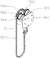
Fig. 8 is a schematic diagram of a mobile structure.
In the figure: a track 1; shuttle 2; a suspension device 3; a hoisting structure 4; a maintenance platform 5; a service frame 501; a U-shaped stop 502; a junction box 503; a connection terminal 504; a crane 6; a support column 7; a bearing housing 701; rotating the lever 702; a bottom support plate 703; a connection hole 704; reinforcing rib plates 705; a horizontal cross beam 8; anti-slip stop 801; an upper support bar 802; side support bars 803; a hanging ring 804; a cable 805; a moving structure 9; roller plate 901; gear plate 902; a roller 903; a passive gear 904; a drive gear 905; an outer gear 906; chain 907.
The specific embodiment is as follows:
the utility model is described in detail below with reference to the attached drawings and detailed description:
the suspension device for shuttle maintenance is provided with a track 1 and a shuttle 2 installed on the track 1, and is further provided with a suspension device 3, the suspension device 3 is used for hoisting and maintenance of the shuttle, the suspension device 3 comprises a hoisting structure 4 and an overhaul platform 5, the hoisting structure 4 comprises a supporting upright 7 and a horizontal cross beam 8 installed on the side edge of the supporting upright 7, a moving structure 9 is further arranged on the horizontal cross beam 8, and a hoisting device 6 is arranged on the moving structure 9.
As shown in fig. 3, a plurality of bearing seats 701 are provided in parallel with each other at the upper portion of the support column 7, bearings are installed in the bearing seats 701, a rotation lever 702 is provided between the bearing seats 701, and the rotation lever 702 is inserted into the bearings so that the rotation lever 702 can freely rotate.
As shown in fig. 2, the horizontal beam 8 is connected to the rotating rod 702, the horizontal beam 8 is fixed to the rotating rod 702, and the rotating rod 702 is freely rotated, so that the horizontal beam 8 can also rotate along with the rotating rod 702, thereby achieving the purpose of rotating the horizontal beam 8.
As shown in fig. 4, the service platform 5 includes a service frame 501 having a hollow interior, the service frame 501 is formed by connecting a plurality of connecting rods, so that maintenance can be performed from the hollow interior of the service platform 5, and U-shaped stoppers 502 are respectively provided at four corners of the upper surface of the service frame 501, so that a shuttle to be serviced can be prevented from sliding down from the service frame 501, thereby improving the safety of the service platform 5.
The maintenance frame 501 is further provided with a junction box 503, the side edge of the junction box 503 is provided with a junction terminal 504, so that electricity is supplied to the shuttle through the junction box 503 and the junction terminal 504, the subsequent maintenance of the shuttle is facilitated, the horizontal cross beam 8 is arranged into an I-shaped structure, the front end and the rear end of the horizontal cross beam 8 are respectively provided with an anti-slip stop block 801, when the movable structure 9 moves on the horizontal cross beam 8, the movable structure cannot slide down from the horizontal cross beam 8, and the lifter 6 is a manual hoist.
As shown in fig. 8, the moving structure 9 includes a roller plate 901 and a gear plate 902 that are parallel to each other, a plurality of rollers 903 are disposed on the inner side of the roller plate 901, a plurality of driven gears 904 are disposed on the inner side of the gear plate 902, a driving gear 905 is disposed between the driven gears 904, the driving gear 905 and the driven gears 904 are meshed with each other, an outer side gear 906 is disposed on the outer side of the gear plate 902, the outer side gear 906 and the driving gear 905 are connected together, a chain 907 is sleeved on the outer side gear 906, such that when the chain 907 is pulled, the chain 907 drives the outer side gear 906 to rotate, and the outer side gear 906 and the driving gear 905 are connected together, such that when the outer side gear 906 rotates, the driving gear 905 rotates and the driven gears 904 are meshed with each other, such that the driven gears 904 also rotate, and the moving structure 9 falls on the horizontal beam 8 through the driven gears 904, such that the moving structure 9 moves through the driven gears 904, and thus the moving structure 9 is realized.
As shown in fig. 5, a cable hoisting frame is arranged at the top of the horizontal beam 8, the cable hoisting frame comprises a plurality of upper support rods 802, the upper support rods 802 are uniformly distributed at the top of the horizontal beam 8, side support rods 803 are arranged at the other side of the upper support rods 802, hanging rings 804 are arranged at the bottoms of the side support rods 803, and cables 805 are sleeved in the hanging rings 804, so that the cables can be conveniently fixed.
The anti-slip stop block 801 is movably connected to the horizontal cross beam 8, namely, the anti-slip stop block 801 is detachable, and when the movable structure 9 needs maintenance, the movable structure 9 can be taken down from the horizontal cross beam 8 by detaching the anti-slip stop block 801.
During the use, rotate horizontal crossbeam 8, horizontal crossbeam 8 rotates to the waiting to overhaul the shuttle top of stopping on track 1 through dwang 702, pulling chain 907, adjust the height of lifting by crane 6, lift the shuttle through lifting by crane 6, the rethread hoist structure 4 with remove structure 9 hoist the shuttle on overhaul platform 5, overhaul the shuttle through overhaul platform 5 can, and overhaul platform 5 is movable, can be according to actual demand like this, adjust the position of overhaul platform 5, and solved traditional overhaul platform and kept away from track 1's way, not only improved maintenance efficiency, still because reduced the travel distance, and improved the security.
It is emphasized that: the above embodiments are merely preferred embodiments of the present utility model, and the present utility model is not limited in any way, and any simple modification, equivalent variation and modification made to the above embodiments according to the technical substance of the present utility model still fall within the scope of the technical solution of the present utility model.
Claims (10)
1. A suspension device for shuttle maintenance is provided with track (1) and install in shuttle (2) on track (1), still be provided with suspension device (3), suspension device (3) are used for the hoist and mount and the maintenance of shuttle, its characterized in that: the suspension device (3) comprises a hoisting structure (4) and an overhaul platform (5), the hoisting structure (4) comprises a supporting upright (7) and a horizontal cross beam (8) arranged on the side edge of the supporting upright (7), a moving structure (9) is further arranged on the horizontal cross beam (8), and a hoisting device (6) is arranged on the moving structure (9).
2. The suspension device for shuttle maintenance according to claim 1, wherein: the upper portion of the support upright post (7) is provided with a plurality of bearing seats (701) which are parallel to each other, a rotating rod (702) is arranged between the bearing seats (701), and the horizontal cross beam (8) is connected to the rotating rod (702).
3. The suspension device for shuttle maintenance according to claim 1, wherein: the overhaul platform (5) comprises an overhaul frame (501) with a hollow inside, the overhaul frame (501) is formed by connecting a plurality of connecting rods, and U-shaped check blocks (502) are respectively arranged on four corners of the upper surface of the overhaul frame (501).
4. A suspension device for shuttle maintenance according to claim 3, characterized in that: and a junction box (503) is further arranged on the overhaul frame (501), and a junction terminal (504) is arranged on the side edge of the junction box (503).
5. The suspension device for shuttle maintenance according to claim 1, wherein: the horizontal cross beam (8) is of an I-shaped structure, and anti-slip stop blocks (801) are respectively arranged at the front end and the rear end of the horizontal cross beam (8).
6. The suspension device for shuttle maintenance according to claim 1, wherein: the movable structure (9) comprises a roller plate (901) and a gear plate (902) which are parallel to each other, a plurality of rollers (903) are arranged on the inner side of the roller plate (901), a plurality of driven gears (904) are arranged on the inner side of the gear plate (902), driving gears (905) are arranged between the driven gears (904), the driving gears (905) and the driven gears (904) are meshed with each other, an outer side gear (906) is arranged on the outer side of the gear plate (902), the outer side gear (906) and the driving gears (905) are connected together, and a chain (907) is sleeved on the outer side gear (906).
7. The suspension device for shuttle maintenance according to claim 1, wherein: the cable lifting frame is arranged at the top of the horizontal cross beam (8), the cable lifting frame comprises a plurality of upper supporting rods (802), the upper supporting rods (802) are uniformly distributed at the top of the horizontal cross beam (8), side supporting rods (803) are arranged at the other side of the upper supporting rods (802), lifting rings (804) are arranged at the bottoms of the side supporting rods (803), and cables (805) are arranged on the lifting rings (804).
8. The suspension device for shuttle maintenance according to claim 1, wherein: the bottom of support stand (7) is provided with bottom support board (703), be provided with a plurality of connecting holes (704) on bottom support board (703), bottom support board (703) with be provided with a plurality of deep floor (705) between support stand (7).
9. The suspension device for shuttle maintenance according to claim 5, wherein: the anti-slip stop block (801) is movably connected to the horizontal cross beam (8).
10. The suspension device for shuttle maintenance according to claim 1, wherein: the lifting device (6) is a hand hoist.
Priority Applications (1)
| Application Number | Priority Date | Filing Date | Title |
|---|---|---|---|
| CN202223180790.5U CN219058347U (en) | 2022-11-30 | 2022-11-30 | Suspension device for maintenance of shuttle |
Applications Claiming Priority (1)
| Application Number | Priority Date | Filing Date | Title |
|---|---|---|---|
| CN202223180790.5U CN219058347U (en) | 2022-11-30 | 2022-11-30 | Suspension device for maintenance of shuttle |
Publications (1)
| Publication Number | Publication Date |
|---|---|
| CN219058347U true CN219058347U (en) | 2023-05-23 |
Family
ID=86363847
Family Applications (1)
| Application Number | Title | Priority Date | Filing Date |
|---|---|---|---|
| CN202223180790.5U Active CN219058347U (en) | 2022-11-30 | 2022-11-30 | Suspension device for maintenance of shuttle |
Country Status (1)
| Country | Link |
|---|---|
| CN (1) | CN219058347U (en) |
-
2022
- 2022-11-30 CN CN202223180790.5U patent/CN219058347U/en active Active
Similar Documents
| Publication | Publication Date | Title |
|---|---|---|
| CN114152828B (en) | Flexible direct-current transmission converter valve submodule power overhaul test device and test method | |
| CN211594267U (en) | A PC stacking floor stacking machine | |
| CN112109037B (en) | Special dismounting device for overhauling unit brake of hydropower station and dismounting method thereof | |
| CN220482076U (en) | Integrated high-speed rail plate demoulding device | |
| CN107827011A (en) | Shallow foundation cheats pallet truck | |
| CN209853572U (en) | Boiler installation overhead hoist | |
| CN215325431U (en) | Automatic product feeding equipment and product transfer trolley | |
| CN220223313U (en) | Hoisting device for locomotive maintenance | |
| CN218174462U (en) | A hoist device for installing promote motor | |
| CN219058340U (en) | Truss hoisting device for maintenance of shuttle | |
| CN217228906U (en) | Trolley layer-changing elevator | |
| CN216686149U (en) | Pipe mould access arrangement | |
| CN217996486U (en) | Container curb plate lifting device | |
| CN221680628U (en) | Portable hoist device | |
| CN224260472U (en) | Mud pumping device | |
| CN217257185U (en) | Steel mould leveling device | |
| CN223804252U (en) | A type of automated warehouse collaborative stacker crane | |
| CN222249911U (en) | Equipment maintenance promotes and uses lifting machine | |
| CN221171675U (en) | Supporting device | |
| CN112517891A (en) | Heavy sand box lifting and conveying equipment | |
| CN224060300U (en) | Supporting conveyor of injection molding machine mould | |
| CN218665035U (en) | Hoisting device for large steel plate bin | |
| CN223950403U (en) | A trolley-type aluminum foil stable feeding mechanism | |
| CN220587247U (en) | Cage lifting device | |
| CN222498532U (en) | Material lifting machine for building engineering |
Legal Events
| Date | Code | Title | Description |
|---|---|---|---|
| GR01 | Patent grant | ||
| GR01 | Patent grant |