CN219050803U - A boiler exhaust gas treatment device - Google Patents
A boiler exhaust gas treatment device Download PDFInfo
- Publication number
- CN219050803U CN219050803U CN202320054231.5U CN202320054231U CN219050803U CN 219050803 U CN219050803 U CN 219050803U CN 202320054231 U CN202320054231 U CN 202320054231U CN 219050803 U CN219050803 U CN 219050803U
- Authority
- CN
- China
- Prior art keywords
- pipe
- fixedly connected
- box
- inlet pipe
- heat
- Prior art date
- Legal status (The legal status is an assumption and is not a legal conclusion. Google has not performed a legal analysis and makes no representation as to the accuracy of the status listed.)
- Expired - Fee Related
Links
- XLYOFNOQVPJJNP-UHFFFAOYSA-N water Substances O XLYOFNOQVPJJNP-UHFFFAOYSA-N 0.000 claims abstract description 67
- 238000010521 absorption reaction Methods 0.000 claims abstract description 20
- 239000002893 slag Substances 0.000 claims description 6
- 230000000694 effects Effects 0.000 abstract description 25
- 239000002912 waste gas Substances 0.000 abstract description 22
- 238000007599 discharging Methods 0.000 abstract description 6
- 239000002918 waste heat Substances 0.000 abstract description 6
- 238000001914 filtration Methods 0.000 abstract description 5
- 239000007789 gas Substances 0.000 description 26
- OKTJSMMVPCPJKN-UHFFFAOYSA-N Carbon Chemical compound [C] OKTJSMMVPCPJKN-UHFFFAOYSA-N 0.000 description 4
- 238000010586 diagram Methods 0.000 description 4
- 239000012535 impurity Substances 0.000 description 3
- 239000002245 particle Substances 0.000 description 3
- 239000007921 spray Substances 0.000 description 3
- 238000006243 chemical reaction Methods 0.000 description 2
- 238000012986 modification Methods 0.000 description 2
- 230000004048 modification Effects 0.000 description 2
- 239000002699 waste material Substances 0.000 description 2
- 239000000446 fuel Substances 0.000 description 1
- 238000000034 method Methods 0.000 description 1
- 239000003595 mist Substances 0.000 description 1
- 230000008092 positive effect Effects 0.000 description 1
- 238000011084 recovery Methods 0.000 description 1
- 238000005507 spraying Methods 0.000 description 1
- 239000000126 substance Substances 0.000 description 1
Images


Classifications
-
- Y—GENERAL TAGGING OF NEW TECHNOLOGICAL DEVELOPMENTS; GENERAL TAGGING OF CROSS-SECTIONAL TECHNOLOGIES SPANNING OVER SEVERAL SECTIONS OF THE IPC; TECHNICAL SUBJECTS COVERED BY FORMER USPC CROSS-REFERENCE ART COLLECTIONS [XRACs] AND DIGESTS
- Y02—TECHNOLOGIES OR APPLICATIONS FOR MITIGATION OR ADAPTATION AGAINST CLIMATE CHANGE
- Y02E—REDUCTION OF GREENHOUSE GAS [GHG] EMISSIONS, RELATED TO ENERGY GENERATION, TRANSMISSION OR DISTRIBUTION
- Y02E20/00—Combustion technologies with mitigation potential
- Y02E20/30—Technologies for a more efficient combustion or heat usage
Landscapes
- Treating Waste Gases (AREA)
Abstract
Description
技术领域technical field
本实用新型涉及锅炉废气处理装置技术领域,尤其涉及一种锅炉废气处理装置。The utility model relates to the technical field of boiler waste gas treatment devices, in particular to a boiler waste gas treatment device.
背景技术Background technique
锅炉是一种能量转换设备,向锅炉输入的能量有燃料中的化学能、电能,锅炉输出具有一定热能的蒸汽、高温水或有机热载体,锅炉进行能量转换的同时会产生废气,其中涉及到锅炉废气处理装置。The boiler is a kind of energy conversion equipment. The energy input to the boiler includes chemical energy and electric energy in the fuel, and the boiler outputs steam, high-temperature water or organic heat carrier with a certain amount of heat energy. When the boiler performs energy conversion, waste gas will be generated, which involves Boiler exhaust gas treatment device.
由于锅炉废气大多是从一些高温的工厂的锅炉中进行排出的,从而导致废气在进行排放时温度都极高,而现有的废气处理装置仅仅只能对废气进行净化过滤而难以对锅炉废气的热量进行回收,因此浪费了大量的热能,为此提出一种锅炉废气处理装置来进行改进和优化。Since the boiler exhaust gas is mostly discharged from the boilers of some high-temperature factories, the temperature of the exhaust gas is extremely high when it is discharged, and the existing exhaust gas treatment device can only purify and filter the exhaust gas, but it is difficult to treat the boiler exhaust gas. The heat is recovered, so a lot of heat energy is wasted, so a boiler exhaust gas treatment device is proposed to improve and optimize.
实用新型内容Utility model content
本实用新型的目的是为了解决现有技术中存在的现有的废气处理装置仅仅只能对废气进行净化过滤而难以对锅炉废气的热量进行回收,因此浪费了大量的热能的问题,而提出的一种锅炉废气处理装置。The purpose of this utility model is to solve the problem that the existing waste gas treatment device in the prior art can only purify and filter the waste gas and is difficult to recover the heat of the boiler waste gas, thus wasting a lot of heat energy. A boiler exhaust gas treatment device.
为了实现上述目的,本实用新型采用了如下技术方案:一种锅炉废气处理装置,包括箱体,所述箱体的内表面固定连接有入风管,所述入风管的一侧外表面固定连接有吸热箱,所述吸热箱的上表面滑动连接有加水管,所述加水管的下表面固定连接有吸热管,所述吸热箱的一侧外表面固定连接有进风管,所述进风管的内表面设置有第二过滤板,所述吸热管的下表面固定连接有排水管,且排水管的外表面与吸热箱的下表面滑动连接。In order to achieve the above object, the utility model adopts the following technical scheme: a boiler exhaust gas treatment device, including a box body, the inner surface of the box body is fixedly connected with an air inlet pipe, and the outer surface of one side of the air inlet pipe is fixed A heat-absorbing box is connected, the upper surface of the heat-absorbing box is slidably connected with a water supply pipe, the lower surface of the water supply pipe is fixedly connected with a heat-absorbing pipe, and the outer surface of one side of the heat-absorbing box is fixedly connected with an air inlet pipe , the inner surface of the air inlet pipe is provided with a second filter plate, the lower surface of the heat absorption pipe is fixedly connected with a drain pipe, and the outer surface of the drain pipe is slidably connected with the lower surface of the heat absorption box.
优选的,所述箱体的上表面固定连接有出风管,所述箱体的下表面固定连接有排渣管。Preferably, an air outlet pipe is fixedly connected to the upper surface of the box, and a slag discharge pipe is fixedly connected to the lower surface of the box.
优选的,所述箱体的内表面开设有凹槽,所述出风管的内表面设置有第一过滤板。Preferably, the inner surface of the box is provided with grooves, and the inner surface of the air outlet pipe is provided with a first filter plate.
优选的,所述凹槽的内表面设置有连接管,所述箱体的外表面滑动连接有入水管,且入水管的一侧外表面与连接管的外表面固定连接。Preferably, a connecting pipe is provided on the inner surface of the groove, a water inlet pipe is slidably connected to the outer surface of the box, and one side outer surface of the water inlet pipe is fixedly connected to the outer surface of the connecting pipe.
优选的,所述入水管的外表面滑动连接有储水箱,所述入水管的下表面固定连接有水泵,所述箱体的下表面固定连接有底座,且底座的上表面与储水箱的下表面固定连接。Preferably, the outer surface of the water inlet pipe is slidably connected to a water storage tank, the lower surface of the water inlet pipe is fixedly connected to a water pump, the lower surface of the box body is fixedly connected to a base, and the upper surface of the base is connected to the lower surface of the water storage tank. Surface fixed connection.
优选的,所述储水箱的上表面固定连接有进水管,所述底座的上表面与吸热箱的下表面固定连接,所述连接管的外表面固定连接有多个雾化喷头,且雾化喷头的外表面与箱体的内表面滑动连接。Preferably, the upper surface of the water storage tank is fixedly connected with a water inlet pipe, the upper surface of the base is fixedly connected with the lower surface of the heat-absorbing box, the outer surface of the connecting pipe is fixedly connected with a plurality of atomizing nozzles, and the mist The outer surface of the spray head is slidingly connected with the inner surface of the box body.
与现有技术相比,本实用新型的优点和积极效果在于,Compared with the prior art, the utility model has the advantages and positive effects that:
1、本实用新型中,通过吸热箱、加水管、吸热管和排水管的设置,达到回收废气余热的效果,避免浪费大量的热能,然后通过第二过滤板的设置,达到将废气中的余渣过滤的效果,且结构简单,达到资源回收的效果。1. In the present utility model, through the setting of the heat absorption box, the water supply pipe, the heat absorption pipe and the drain pipe, the effect of recovering the waste heat of the exhaust gas can be achieved, and a large amount of heat energy can be avoided, and then through the setting of the second filter plate, the exhaust gas The effect of residue filtration, and the structure is simple, to achieve the effect of resource recovery.
2、本实用新型中,通过第一过滤板的设置,达到对废气进行过滤的效果,通过储水箱、水泵和入水管的设置,达到向雾化喷头内提供水的效果,通过出风管的设置,达到将达到排放标准的废气排放出去的效果,通过连接管、凹槽和雾化喷头的设置,达到全范围对箱体内喷洒水汽的效果,从而达到废气处理的效果。2. In the utility model, through the setting of the first filter plate, the effect of filtering the waste gas is achieved; through the setting of the water storage tank, the water pump and the water inlet pipe, the effect of providing water to the atomizing nozzle is achieved; The setting is to achieve the effect of discharging the exhaust gas that meets the emission standard. Through the setting of the connecting pipe, groove and atomizing nozzle, the effect of spraying water vapor on the box in a full range is achieved, so as to achieve the effect of exhaust gas treatment.
附图说明Description of drawings
图1为本实用新型提出一种锅炉废气处理装置的正视结构示意图;Fig. 1 is a front structural schematic diagram of a boiler waste gas treatment device proposed by the utility model;
图2为本实用新型提出一种锅炉废气处理装置的仰视结构示意图;Fig. 2 is a schematic view of the structure of a boiler waste gas treatment device proposed by the utility model;
图3为本实用新型提出一种锅炉废气处理装置的吸热管结构示意图;Fig. 3 is a structural schematic diagram of a heat absorbing tube of a boiler waste gas treatment device proposed by the present invention;
图4为本实用新型提出一种锅炉废气处理装置的雾化喷头结构示意图;Fig. 4 is a structural schematic diagram of an atomizing nozzle of a boiler exhaust gas treatment device proposed by the utility model;
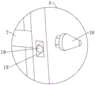
图5为图3中A处的放大结构示意图。FIG. 5 is a schematic diagram of an enlarged structure at point A in FIG. 3 .
图例说明:1、箱体;2、出风管;3、储水箱;4、吸热箱;5、底座;6、进水管;7、入水管;8、第一过滤板;9、进风管;10、加水管;11、入风管;12、水泵;13、排渣管;14、排水管;15、第二过滤板;16、雾化喷头;17、吸热管;18、凹槽;19、连接管。Legend: 1. Box body; 2. Air outlet pipe; 3. Water storage tank; 4. Heat absorption box; 5. Base; 6. Water inlet pipe; 7. Water inlet pipe; 8. First filter plate; 9.
具体实施方式Detailed ways
为了能够更清楚地理解本实用新型的上述目的、特征和优点,下面结合附图和实施例对本实用新型做进一步说明。需要说明的是,在不冲突的情况下,本申请的实施例及实施例中的特征可以相互组合。In order to understand more clearly the above purpose, features and advantages of the utility model, the utility model will be further described below in conjunction with the accompanying drawings and embodiments. It should be noted that, in the case of no conflict, the embodiments of the present application and the features in the embodiments can be combined with each other.
在下面的描述中阐述了很多具体细节以便于充分理解本实用新型,但是,本实用新型还可以采用不同于在此描述的其他方式来实施,因此,本实用新型并不限于下面公开说明书的具体实施例的限制。In the following description, a lot of specific details have been set forth in order to fully understand the utility model, but the utility model can also be implemented in other ways that are different from those described here. Therefore, the utility model is not limited to the specific details of the following disclosure EXAMPLE LIMITATIONS.
实施例1,如图1-图5所示,本实用新型提供了一种锅炉废气处理装置,包括箱体1,箱体1的内表面固定连接有入风管11,入风管11的一侧外表面固定连接有吸热箱4,吸热箱4的上表面滑动连接有加水管10,加水管10的下表面固定连接有吸热管17,吸热箱4的一侧外表面固定连接有进风管9,进风管9的内表面设置有第二过滤板15,吸热管17的下表面固定连接有排水管14,且排水管14的外表面与吸热箱4的下表面滑动连接。
其整个实施例1达到的效果为,通过吸热箱4的设置,达到将废气的余热进行回收的效果,避免造成热能浪费,通过加水管10的设置,达到向吸热管17注入冷水的效果,然后通过排水管14的设置,达到将因为吸收废气余热而转化的热水排出进行利用的效果,从而达到回收废气余热的效果,通过吸热管17的设置,达到吸取从进风管9进入的废气余热的效果,避免资源浪费,通过第二过滤板15的设置,达到将废气中的余渣过滤的效果,避免余渣进入到吸热箱4,使得吸热箱4变得污脏。The effect achieved in the
实施例2,如图1-图5所示,箱体1的上表面固定连接有出风管2,箱体1的下表面固定连接有排渣管13,箱体1的内表面开设有凹槽18,出风管2的内表面设置有第一过滤板8,凹槽18的内表面设置有连接管19,箱体1的外表面滑动连接有入水管7,且入水管7的一侧外表面与连接管19的外表面固定连接,入水管7的外表面滑动连接有储水箱3,入水管7的下表面固定连接有水泵12,箱体1的下表面固定连接有底座5,且底座5的上表面与储水箱3的下表面固定连接,储水箱3的上表面固定连接有进水管6,底座5的上表面与吸热箱4的下表面固定连接,连接管19的外表面固定连接有多个雾化喷头16,且雾化喷头16的外表面与箱体1的内表面滑动连接。
其整个实施例2达到的效果为,通过第一过滤板8的设置,达到对废气进行过滤的效果,且第一过滤板8处可以放置活性炭,对废气再次进行过滤的处理,通过储水箱3、水泵12和入水管7的设置,达到向箱体1内提供水的效果,从而通过雾化喷头16喷洒的水将废气中的杂质颗粒冲刷掉落,通过排渣管13排出,从而达到废气处理的效果,通过出风管2的设置,达到将达到排放标准的废气排放出去的效果,通过连接管19、凹槽18和雾化喷头16的设置,达到全范围对箱体1内喷洒水汽的效果,从而使得可以和废气充分接触,将杂质颗粒冲刷掉。The effect achieved by the
工作原理:先将废气从进风管9内进入到吸热箱4,通过第二过滤板15进行初步过滤,避免废气中残渣进入吸热箱4,然后通过加水管10对吸热管17注入冷水,吸热管17与吸热箱4内的高温废气进行接触降温,使得吸热管17的冷水变为热水然后从排水管14处排出收集利用,经过冷却的废气从入风管11处进入到箱体1内,然后通过进水管6向储水箱3内加水,再通过水泵12从入水管7、连接管19向雾化喷头16喷出,使得箱体1内的废气与水汽充分接触,雾化喷头16喷洒的水将废气中的杂质颗粒冲刷掉落,通过排渣管13排出,废气再经过第一过滤板8和第一过滤板8上放置的活性炭进行再次过滤,然后从出风管2处排出达标的废气。Working principle: Firstly, the exhaust gas enters the
以上所述,仅是本实用新型的较佳实施例而已,并非是对本实用新型作其它形式的限制,任何熟悉本专业的技术人员可能利用上述揭示的技术内容加以变更或改型为等同变化的等效实施例应用于其它领域,但是凡是未脱离本实用新型技术方案内容,依据本实用新型的技术实质对以上实施例所作的任何简单修改、等同变化与改型,仍属于本实用新型技术方案的保护范围。The above is only a preferred embodiment of the utility model, and is not intended to limit the utility model in other forms. Any skilled person who is familiar with this profession may use the technical content disclosed above to change or remodel it into an equivalent change. The equivalent embodiments are applied to other fields, but any simple modifications, equivalent changes and modifications made to the above embodiments according to the technical essence of the present invention without departing from the content of the technical solution of the present utility model still belong to the technical solution of the present utility model scope of protection.
Claims (6)
Priority Applications (1)
| Application Number | Priority Date | Filing Date | Title |
|---|---|---|---|
| CN202320054231.5U CN219050803U (en) | 2023-01-09 | 2023-01-09 | A boiler exhaust gas treatment device |
Applications Claiming Priority (1)
| Application Number | Priority Date | Filing Date | Title |
|---|---|---|---|
| CN202320054231.5U CN219050803U (en) | 2023-01-09 | 2023-01-09 | A boiler exhaust gas treatment device |
Publications (1)
| Publication Number | Publication Date |
|---|---|
| CN219050803U true CN219050803U (en) | 2023-05-23 |
Family
ID=86343619
Family Applications (1)
| Application Number | Title | Priority Date | Filing Date |
|---|---|---|---|
| CN202320054231.5U Expired - Fee Related CN219050803U (en) | 2023-01-09 | 2023-01-09 | A boiler exhaust gas treatment device |
Country Status (1)
| Country | Link |
|---|---|
| CN (1) | CN219050803U (en) |
-
2023
- 2023-01-09 CN CN202320054231.5U patent/CN219050803U/en not_active Expired - Fee Related
Similar Documents
| Publication | Publication Date | Title |
|---|---|---|
| CN105258144B (en) | A kind of fountain flue gas waste heat recovery apparatus | |
| CN209362161U (en) | A low-temperature flue gas waste heat recovery and purification system for alumina roasting furnace | |
| CN202626213U (en) | Device for generating hot water by using waste heat of blast furnace slag | |
| CN105258143A (en) | Spray type flue gas waste heat recycling device | |
| CN206463697U (en) | One kind circulation high-pressure spraying pond | |
| CN205119109U (en) | Flue gas recovery system | |
| CN205065764U (en) | Fountain residual heat from flue gas device | |
| CN115790181A (en) | Waste heat step recovery structure and recovery method for electric furnace steelmaking | |
| CN211753903U (en) | Novel protection of high temperature flue gas washing tower device | |
| CN209865774U (en) | Flue gas denitration device for improving vaporization effect of ammonia water | |
| CN208845242U (en) | A kind of steel mill's flue gas waste heat power generation device | |
| CN107245343A (en) | A high-temperature steam treatment method for wet coke quenching | |
| CN208229648U (en) | A kind of equipment that wet denitration reaction solution removes condensed water in removing exhaust gas | |
| CN213643145U (en) | Methanol evaporation system for formaldehyde production | |
| CN206064038U (en) | Flue gas cool-down dust arrester | |
| CN202082902U (en) | Flue gas residual heat boiler | |
| CN223628398U (en) | A boiler denitrification circulation treatment device | |
| CN219414844U (en) | A high temperature exhaust gas treatment device | |
| CN204672124U (en) | A kind of waste gas treatment equipment | |
| CN218422037U (en) | A VOCs treatment device | |
| CN223925442U (en) | Safe and environment-friendly type molten salt furnace tail gas heat exchanger | |
| CN212508574U (en) | Engine waste heat utilization system | |
| CN213253798U (en) | Adjustable boiler waste heat recovery exhaust device | |
| CN205065763U (en) | Fountain residual heat from flue gas device | |
| CN214075973U (en) | Built-in heating urea pyrolysis denitrification facility |
Legal Events
| Date | Code | Title | Description |
|---|---|---|---|
| GR01 | Patent grant | ||
| GR01 | Patent grant | ||
| CF01 | Termination of patent right due to non-payment of annual fee | ||
| CF01 | Termination of patent right due to non-payment of annual fee |
Granted publication date: 20230523 |