CN219042791U - Anesthesia instrument table - Google Patents
Anesthesia instrument table Download PDFInfo
- Publication number
- CN219042791U CN219042791U CN202222751584.9U CN202222751584U CN219042791U CN 219042791 U CN219042791 U CN 219042791U CN 202222751584 U CN202222751584 U CN 202222751584U CN 219042791 U CN219042791 U CN 219042791U
- Authority
- CN
- China
- Prior art keywords
- fixedly connected
- driving
- control box
- rod
- storage box
- Prior art date
- Legal status (The legal status is an assumption and is not a legal conclusion. Google has not performed a legal analysis and makes no representation as to the accuracy of the status listed.)
- Expired - Fee Related
Links
Images



Landscapes
- Accommodation For Nursing Or Treatment Tables (AREA)
Abstract
本实用新型公开了一种麻醉器械台,包括底座和固定连接在底座顶端的推把,所述底座的顶端且远离推把的一侧固定连接有控制箱,所述控制箱的顶端固定连接有收纳箱,本实用新型涉及医疗器械技术领域。该麻醉器械台,通过在控制箱的内部设置传动机构,传动电机的输出端通过联轴器配合螺纹杆带动螺纹套移动,通过螺纹套带动驱动杆配合连杆,使连杆带动另一个驱动杆移动,从而带动滑块在滑杆外表面滑动,两个驱动杆在移动的同时通过配合两个驱动块,使驱动块在滑槽的内表面滑动,从而带动器械放置架在收纳箱的内部上下滑动,由此对器械放置架进行升降,使其在不用时能够收进收纳箱的内部,从而减小占用面积,给主刀医生到来便利。
The utility model discloses an anesthesia instrument table, which comprises a base and a push handle fixedly connected to the top of the base. A control box is fixedly connected to the top of the base and the side away from the push handle. A storage box, the utility model relates to the technical field of medical instruments. In this anesthesia instrument table, by setting a transmission mechanism inside the control box, the output end of the transmission motor drives the threaded sleeve to move through the coupling and the threaded rod, and drives the driving rod to cooperate with the connecting rod through the threaded sleeve, so that the connecting rod drives another driving rod. Move, thereby driving the slider to slide on the outer surface of the slider, and the two driving rods cooperate with the two driving blocks at the same time to make the driving block slide on the inner surface of the chute, thereby driving the instrument placement rack up and down inside the storage box Sliding, thereby lifting and lowering the instrument storage rack, so that it can be stored inside the storage box when not in use, thereby reducing the occupied area and making it convenient for the surgeon to arrive.
Description
技术领域technical field
本实用新型涉及医疗器械技术领域,具体为一种麻醉器械台。The utility model relates to the technical field of medical equipment, in particular to an anesthesia equipment table.
背景技术Background technique
现有的麻醉器械台在进行使用时需要由医护人员将器械传递给主刀医生,因麻醉器械台的占用面积较大,且结构固定,当不需要用到时,不便于进行收纳,且还会给主刀医生带来困扰。The existing anesthesia equipment table needs to be passed by the medical staff to the chief surgeon when it is used. Because the anesthesia equipment table occupies a large area and has a fixed structure, it is not convenient to store when it is not needed, and it will also Bring trouble to the surgeon.
实用新型内容Utility model content
针对现有技术的不足,本实用新型提供了一种麻醉器械台,解决了麻醉器械台在进行使用时需要由医护人员将器械传递给主刀医生,因麻醉器械台的占用面积较大,且结构固定,当不需要用到时,不便于进行收纳,且还会给主刀医生带来困扰的问题。Aiming at the deficiencies of the prior art, the utility model provides an anesthesia instrument table, which solves the problem that the anesthesia instrument table needs to be passed by the medical staff to the chief surgeon when the anesthesia instrument table is in use. Fixed, when not in use, it is not convenient to store, and it will also bring troubles to the surgeon.
为实现以上目的,本实用新型通过以下技术方案予以实现:一种麻醉器械台,包括底座和固定连接在底座顶端的推把,所述底座的顶端且远离推把的一侧固定连接有控制箱,所述控制箱的顶端固定连接有收纳箱,所述收纳箱的内壁滑动连接有器械放置架,所述器械放置架的两侧均开设有滑槽,所述控制箱的内部设有带动器械放置架进行升降的传动机构。In order to achieve the above purpose, the utility model is achieved through the following technical solutions: an anesthesia instrument table, including a base and a push handle fixedly connected to the top of the base, a control box is fixedly connected to the top of the base and the side away from the push handle , the top of the control box is fixedly connected with a storage box, the inner wall of the storage box is slidably connected with an instrument placement frame, both sides of the instrument placement frame are provided with chute, and the inside of the control box is provided with a driving instrument The transmission mechanism for lifting and lowering the rack.
优选的,所述传动机构包括固定连接在控制箱内壁的支撑板,所述支撑板的一侧与控制箱的内壁之间转动连接有螺纹杆,所述螺纹杆的外表面螺纹连接有螺纹套,所述螺纹杆的一端贯穿至支撑板的一侧且通过联轴器固定连接有传动电机,且传动电机与控制箱的表面上方固定连接。Preferably, the transmission mechanism includes a support plate fixedly connected to the inner wall of the control box, a threaded rod is rotatably connected between one side of the support plate and the inner wall of the control box, and a threaded sleeve is threaded on the outer surface of the threaded rod , one end of the threaded rod penetrates to one side of the support plate and is fixedly connected to a transmission motor through a coupling, and the transmission motor is fixedly connected to the upper surface of the control box.
优选的,所述支撑板的一侧与控制箱的内壁之间,且远离螺纹杆的外表面固定连接有滑杆,所述滑杆的外表面滑动连接有滑块,且滑块与螺纹套的顶端均固定连接有驱动杆。Preferably, a slide bar is fixedly connected between one side of the support plate and the inner wall of the control box and away from the outer surface of the threaded rod, the outer surface of the slide bar is slidably connected with a slider, and the slider and the threaded sleeve The top ends are fixedly connected with drive rods.
优选的,两个所述驱动杆的内表面连通固定有连杆,所述连杆的外表面滑动连接有限位块,且限位块的两端与支撑板和控制箱的相对侧之间固定连接。Preferably, the inner surfaces of the two driving rods are communicated with and fixed to the connecting rod, the outer surface of the connecting rod is slidably connected to the limit block, and the two ends of the limit block are fixed between the support plate and the opposite side of the control box. connect.
优选的,两个所述驱动杆的一端均依次贯穿控制箱与收纳箱,至收纳箱的内部,且固定连接有驱动块,两个所述驱动块的外表面均与滑槽的内表面滑动连接。Preferably, one end of the two driving rods passes through the control box and the storage box in turn, to the inside of the storage box, and is fixedly connected with a driving block, and the outer surfaces of the two driving blocks slide with the inner surface of the chute connect.
优选的,所述器械放置架的内壁滑动连接有分层板,所述分层板的顶端固定连接有凸起块。Preferably, a layered plate is slidably connected to the inner wall of the instrument placement frame, and a raised block is fixedly connected to the top of the layered plate.
有益效果Beneficial effect
本实用新型提供了一种麻醉器械台。与现有技术相比具备以下有益效果:The utility model provides an anesthesia instrument table. Compared with the prior art, it has the following beneficial effects:
该麻醉器械台,通过在控制箱的内部设置传动机构,传动电机的输出端通过联轴器配合螺纹杆带动螺纹套移动,通过螺纹套带动驱动杆配合连杆,使连杆带动另一个驱动杆移动,从而带动滑块在滑杆外表面滑动,两个驱动杆在移动的同时通过配合两个驱动块,使驱动块在滑槽的内表面滑动,从而带动器械放置架在收纳箱的内部上下滑动,由此对器械放置架进行升降,使其在不用时能够收进收纳箱的内部,从而减小占用面积,给主刀医生到来便利。In this anesthesia instrument table, by setting a transmission mechanism inside the control box, the output end of the transmission motor drives the threaded sleeve to move through the coupling and the threaded rod, and drives the driving rod to cooperate with the connecting rod through the threaded sleeve, so that the connecting rod drives another driving rod. Move, thereby driving the slider to slide on the outer surface of the slide bar, and the two drive rods cooperate with the two drive blocks at the same time to make the drive block slide on the inner surface of the chute, thereby driving the instrument placement rack up and down inside the storage box Sliding, thereby lifting and lowering the instrument storage rack, so that it can be stored inside the storage box when not in use, thereby reducing the occupied area and making it convenient for the surgeon to arrive.
附图说明Description of drawings
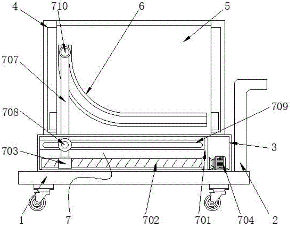
图1为本实用新型的整体结构示意图;Fig. 1 is the overall structural representation of the utility model;
图2为本实用新型的器械放置架升起状态示意图;Fig. 2 is a schematic diagram of the rising state of the instrument placement rack of the present invention;
图3为本实用新型的局部结构侧剖图;Fig. 3 is a partial structural side sectional view of the present utility model;
图4为本实用新型的传动机构俯视图。Fig. 4 is a top view of the transmission mechanism of the present invention.
图中:1、底座;2、推把;3、控制箱;4、收纳箱;5、器械放置架;6、滑槽;7、传动机构;701、支撑板;702、螺纹杆;703、螺纹套;704、传动电机;705、滑杆;706、滑块;707、驱动杆;708、连杆;709、限位块;710、驱动块;8、分层板;9、凸起块。In the figure: 1. Base; 2. Push handle; 3. Control box; 4. Storage box; 5. Instrument rack; 6. Chute; 7. Transmission mechanism; Thread sleeve; 704, transmission motor; 705, sliding rod; 706, sliding block; 707, driving rod; 708, connecting rod; 709, limit block; 710, driving block; .
具体实施方式Detailed ways
下面将结合本实用新型实施例中的附图,对本实用新型实施例中的技术方案进行清楚、完整地描述,显然,所描述的实施例仅仅是本实用新型一部分实施例,而不是全部的实施例。基于本实用新型中的实施例,本领域普通技术人员在没有做出创造性劳动前提下所获得的所有其他实施例,都属于本实用新型保护的范围。The technical solutions in the embodiments of the present invention will be clearly and completely described below in conjunction with the accompanying drawings in the embodiments of the present invention. Obviously, the described embodiments are only part of the embodiments of the present invention, not all of them. example. Based on the embodiments of the present utility model, all other embodiments obtained by persons of ordinary skill in the art without making creative efforts belong to the scope of protection of the present utility model.
请参阅图1-4,本实用新型提供两种技术方案:Please refer to Figure 1-4, the utility model provides two technical solutions:
实施例一:一种麻醉器械台,包括底座1和固定连接在底座1顶端的推把2,底座1的底端设有滚轮,通过推动推把2带动滚轮滚动,从而带动器械台进行移动,底座1的顶端且远离推把2的一侧固定连接有控制箱3,控制箱3的顶端固定连接有收纳箱4,收纳箱4用来对器械放置架5进行收纳存放,收纳箱4的内壁滑动连接有器械放置架5,收纳箱4的内壁设有凹槽,器械放置架5的两侧设有卡块,该卡块与收纳箱4的凹槽适配,器械放置架5通过卡块在收纳箱4的凹槽内滑动,来使器械放置架5收入或是伸出至收纳箱4的内部,器械放置架5的两侧均开设有滑槽6,滑槽6设为弧形,控制箱3的内部设有带动器械放置架5进行升降的传动机构7,传动机构7包括固定连接在控制箱3内壁的支撑板701,支撑板701的一侧与控制箱3的内壁之间转动连接有螺纹杆702,支撑板701对螺纹杆702起到支撑限位的作用,螺纹杆702的外表面螺纹连接有螺纹套703,螺纹杆702的一端贯穿至支撑板701的一侧且通过联轴器固定连接有传动电机704,传动电机704为三相异步电机可带动螺纹杆702进行正反转,且通过对应的控制开关与外部电源电性连接,且传动电机704与控制箱3的表面上方固定连接,通过启动传动电机704,传动电机704的输出端通过联轴器带动螺纹杆702转动,通过螺纹杆702转动带动外表面的螺纹套703进行移动,支撑板701的一侧与控制箱3的内壁之间,且远离螺纹杆702的外表面固定连接有滑杆705,滑杆705的外表面滑动连接有滑块706,且滑块706与螺纹套703的顶端均固定连接有驱动杆707,两个驱动杆707的内表面连通固定有连杆708,连杆708贯穿两个驱动杆707的内表面与其固定连接,连杆708的外表面滑动连接有限位块709,限位块709的内壁贯穿开设有开口槽,且开口槽与连杆708适配,当螺纹杆702带动螺纹套703移动时,螺纹套703顶端的驱动杆707则带动连杆708在限位块709的开口槽内表面滑动,滑动的同时带动连杆708另一端所连接的驱动杆707移动,通过该驱动杆707带动滑块706在滑杆705的外表面滑动,从而配合螺纹套703一起带动两个驱动杆707进行移动,且限位块709的两端与支撑板701和控制箱3的相对侧之间固定连接,两个驱动杆707的一端均依次贯穿控制箱3与收纳箱4,至收纳箱4的内部,且固定连接有驱动块710,控制箱3顶端与收纳箱4的底端均贯穿开设有开口槽,且两个开口槽均与驱动杆707适配,当滑块706与螺纹套703带动两个驱动杆707移动时,两个驱动杆707的外表面则在控制箱3与收纳箱4的开口槽内表面滑动,两个驱动块710的外表面均与滑槽6的内表面滑动连接,两个驱动杆707在滑动的同时各自带动一端所连接的驱动块710,使驱动块710的外表面在滑槽6的内表面滑动,从而通过滑槽6所设定的弧形,在滑动的同时带动器械放置架5进行升降,方便对其进行收纳,器械放置架5的内壁滑动连接有分层板8,器械放置架5的内壁设有凹槽,该凹槽与分层板8适配,分层板8的外表面通过在器械放置架5内壁所设置的凹槽内滑动,来对分层板8上端放置的器械进行拿取,分层板8的顶端固定连接有凸起块9,通过外力拉动凸起块9从而使分层板8,滑出器械放置架5的内部。Embodiment 1: An anesthesia instrument table includes a
实施例二:一种麻醉器械台,包括在控制箱3的内部设置带动器械放置架5进行升降的传动机构7,传动机构7包括固定连接在控制箱3内壁的支撑板701,支撑板701的一侧与控制箱3的内壁之间转动连接有螺纹杆702,支撑板701对螺纹杆702起到支撑限位的作用,螺纹杆702的外表面螺纹连接有螺纹套703,螺纹杆702的一端贯穿至支撑板701的一侧且通过联轴器固定连接有传动电机704,传动电机704为三相异步电机可带动螺纹杆702进行正反转,且通过对应的控制开关与外部电源电性连接,且传动电机704与控制箱3的表面上方固定连接,通过启动传动电机704,传动电机704的输出端通过联轴器带动螺纹杆702转动,通过螺纹杆702转动带动外表面的螺纹套703进行移动,支撑板701的一侧与控制箱3的内壁之间,且远离螺纹杆702的外表面固定连接有滑杆705,滑杆705的外表面滑动连接有滑块706,且滑块706与螺纹套703的顶端均固定连接有驱动杆707,两个驱动杆707的内表面连通固定有连杆708,连杆708贯穿两个驱动杆707的内表面与其固定连接,连杆708的外表面滑动连接有限位块709,限位块709的内壁贯穿开设有开口槽,且开口槽与连杆708适配,当螺纹杆702带动螺纹套703移动时,螺纹套703顶端的驱动杆707则带动连杆708在限位块709的开口槽内表面滑动,滑动的同时带动连杆708另一端所连接的驱动杆707移动,通过该驱动杆707带动滑块706在滑杆705的外表面滑动,从而配合螺纹套703一起带动两个驱动杆707进行移动,且限位块709的两端与支撑板701和控制箱3的相对侧之间固定连接,两个驱动杆707的一端均依次贯穿控制箱3与收纳箱4,至收纳箱4的内部,且固定连接有驱动块710,控制箱3顶端与收纳箱4的底端均贯穿开设有开口槽,且两个开口槽均与驱动杆707适配,当滑块706与螺纹套703带动两个驱动杆707移动时,两个驱动杆707的外表面则在控制箱3与收纳箱4的开口槽内表面滑动,两个驱动块710的外表面均与滑槽6的内表面滑动连接,两个驱动杆707在滑动的同时各自带动一端所连接的驱动块710,使驱动块710的外表面在滑槽6的内表面滑动,从而通过滑槽6所设定的弧形,在滑动的同时带动器械放置架5进行升降,方便对其进行收纳。Embodiment 2: a kind of anesthesia apparatus table, comprises the
同时本说明书中未作详细描述的内容均属于本领域技术人员公知的现有技术。At the same time, the content not described in detail in this specification belongs to the prior art known to those skilled in the art.
工作时,当需要用到麻醉器械台时,医护人员通过推把2将器械台推送至需要用到的地方,随后通过启动传动电机704,传动电机704的输出端通过联轴器带动螺纹杆702转动,螺纹杆702在转动的过程中带动外表面所连接的螺纹套703移动,螺纹套703在移动的同时带动顶端的驱动杆707移动,通过驱动杆707的移动带动内表面所连接的连杆708,使连杆708在限位块709的内表面滑动,滑动的同时带动连杆708另一端所连接的另一个驱动杆707,通过另一个驱动杆707带动滑块706在滑杆705的外表面滑动,从而通过滑块706与螺纹套703的配合带动两个驱动杆707移动,两个驱动杆707在移动的同时带动一端所连接的驱动块710,使驱动块710的外表面在滑槽6的内表面滑动,通过滑槽6所设定的滑道,在驱动块710滑动的同时带动器械放置架5在收纳箱4的内表面滑动,从而使其顶端伸出至收纳箱4的外部,再通过拉动凸起块9,通过凸起块9带动分层板8在器械放置架5的内壁滑动,从而将其拉出至器械放置架5的一侧外部,即可对分层板8上放置的器械进行拿取使用,当不需要用到麻醉器械台时,通过传动电机704的输出端带动螺纹杆702进行反转,则可通过驱动杆707带动驱动块710向回滑动,从而可带动器械放置架5下降,将其收入至收纳箱4的内部即可。During work, when the anesthesia instrument table needs to be used, the medical staff pushes the instrument table to the place where it needs to be used through the
需要说明的是,在本文中,诸如第一和第二等之类的关系术语仅仅用来将一个实体或者操作与另一个实体或操作区分开来,而不一定要求或者暗示这些实体或操作之间存在任何这种实际的关系或者顺序。而且,术语“包括”、“包含”或者其任何其他变体意在涵盖非排他性的包含,从而使得包括一系列要素的过程、方法、物品或者设备不仅包括那些要素,而且还包括没有明确列出的其他要素,或者是还包括为这种过程、方法、物品或者设备所固有的要素。It should be noted that in this article, relational terms such as first and second are only used to distinguish one entity or operation from another entity or operation, and do not necessarily require or imply that there is a relationship between these entities or operations. There is no such actual relationship or order between them. Furthermore, the term "comprises", "comprises" or any other variation thereof is intended to cover a non-exclusive inclusion such that a process, method, article, or apparatus comprising a set of elements includes not only those elements, but also includes elements not expressly listed. other elements of or also include elements inherent in such a process, method, article, or device.
尽管已经示出和描述了本实用新型的实施例,对于本领域的普通技术人员而言,可以理解在不脱离本实用新型的原理和精神的情况下可以对这些实施例进行多种变化、修改、替换和变型,本实用新型的范围由所附权利要求及其等同物限定。Although the embodiments of the present invention have been shown and described, those skilled in the art can understand that various changes and modifications can be made to these embodiments without departing from the principle and spirit of the present invention , replacements and modifications, the scope of the present utility model is defined by the appended claims and their equivalents.
Claims (6)
Priority Applications (1)
| Application Number | Priority Date | Filing Date | Title |
|---|---|---|---|
| CN202222751584.9U CN219042791U (en) | 2022-10-19 | 2022-10-19 | Anesthesia instrument table |
Applications Claiming Priority (1)
| Application Number | Priority Date | Filing Date | Title |
|---|---|---|---|
| CN202222751584.9U CN219042791U (en) | 2022-10-19 | 2022-10-19 | Anesthesia instrument table |
Publications (1)
| Publication Number | Publication Date |
|---|---|
| CN219042791U true CN219042791U (en) | 2023-05-19 |
Family
ID=86320801
Family Applications (1)
| Application Number | Title | Priority Date | Filing Date |
|---|---|---|---|
| CN202222751584.9U Expired - Fee Related CN219042791U (en) | 2022-10-19 | 2022-10-19 | Anesthesia instrument table |
Country Status (1)
| Country | Link |
|---|---|
| CN (1) | CN219042791U (en) |
Cited By (1)
| Publication number | Priority date | Publication date | Assignee | Title |
|---|---|---|---|---|
| CN118356072A (en) * | 2024-04-17 | 2024-07-19 | 中建科工集团运营管理有限公司 | A mobile display stand for exhibition center |
-
2022
- 2022-10-19 CN CN202222751584.9U patent/CN219042791U/en not_active Expired - Fee Related
Cited By (1)
| Publication number | Priority date | Publication date | Assignee | Title |
|---|---|---|---|---|
| CN118356072A (en) * | 2024-04-17 | 2024-07-19 | 中建科工集团运营管理有限公司 | A mobile display stand for exhibition center |
Similar Documents
| Publication | Publication Date | Title |
|---|---|---|
| CN115319202B (en) | Neodymium iron boron rare earth permanent magnet does not have material processing of boiling and uses holding fixture and cutting equipment | |
| CN213290175U (en) | Rotary table workpiece clamping device | |
| CN207814839U (en) | A height-increasing bracket for facilitating the heightening of a display | |
| CN206270643U (en) | A portable projection screen with synchronous lifting device | |
| CN219053074U (en) | Get tubular product cutting device for dinner cabinet | |
| CN215660098U (en) | Medical joint fixing device convenient to clamp | |
| CN211708811U (en) | A cutting device for cutting linear guide rails | |
| CN212345791U (en) | Workstation for building management with regulatory function | |
| CN208627370U (en) | A kind of paediatrics test tube for blood test frame | |
| CN219856135U (en) | A pressing device | |
| CN221266585U (en) | Auxiliary stand for delivery room nursing | |
| CN219190188U (en) | Rack for building engineering | |
| CN220735498U (en) | Anesthesia table | |
| CN221797983U (en) | Rack of yardage roll cutting platform | |
| CN218259784U (en) | A textile roll storage device for a textile production workshop | |
| CN222130242U (en) | Fast folding medical cart | |
| CN220833146U (en) | Medical imaging equipment adjusting workbench | |
| CN220987588U (en) | Sterilization equipment is used in food production | |
| CN219561975U (en) | Pressing device for welding electronic device | |
| CN218518610U (en) | Platform is used in electronic components processing | |
| CN213780124U (en) | Stabilize effectual plant extract detection device | |
| CN218607199U (en) | Nursing rack with lifting function | |
| CN224162821U (en) | An adjustable refrigerator base | |
| CN220975327U (en) | PVC section bar production is with receiving device convenient to clearance | |
| CN222340855U (en) | Industrial design picture paper hanging device |
Legal Events
| Date | Code | Title | Description |
|---|---|---|---|
| GR01 | Patent grant | ||
| GR01 | Patent grant | ||
| CF01 | Termination of patent right due to non-payment of annual fee | ||
| CF01 | Termination of patent right due to non-payment of annual fee |
Granted publication date: 20230519 |