CN219042507U - Garden Slope Greening Structure - Google Patents
Garden Slope Greening Structure Download PDFInfo
- Publication number
- CN219042507U CN219042507U CN202320053978.9U CN202320053978U CN219042507U CN 219042507 U CN219042507 U CN 219042507U CN 202320053978 U CN202320053978 U CN 202320053978U CN 219042507 U CN219042507 U CN 219042507U
- Authority
- CN
- China
- Prior art keywords
- fixedly connected
- threaded rod
- motor
- casing
- water tank
- Prior art date
- Legal status (The legal status is an assumption and is not a legal conclusion. Google has not performed a legal analysis and makes no representation as to the accuracy of the status listed.)
- Expired - Fee Related
Links
Images


Classifications
-
- Y—GENERAL TAGGING OF NEW TECHNOLOGICAL DEVELOPMENTS; GENERAL TAGGING OF CROSS-SECTIONAL TECHNOLOGIES SPANNING OVER SEVERAL SECTIONS OF THE IPC; TECHNICAL SUBJECTS COVERED BY FORMER USPC CROSS-REFERENCE ART COLLECTIONS [XRACs] AND DIGESTS
- Y02—TECHNOLOGIES OR APPLICATIONS FOR MITIGATION OR ADAPTATION AGAINST CLIMATE CHANGE
- Y02A—TECHNOLOGIES FOR ADAPTATION TO CLIMATE CHANGE
- Y02A20/00—Water conservation; Efficient water supply; Efficient water use
- Y02A20/108—Rainwater harvesting
Landscapes
- Catching Or Destruction (AREA)
Abstract
本实用新型公开了园林坡面绿化结构,包括壳体,所述壳体的上表面开设有通口,所述通口的内壁滑动连接有控制板,所述控制板的正面开设有螺纹孔,所述壳体的正面和壳体的背面均固定镶嵌有轴承,所述螺纹孔的内壁螺纹连接有螺纹杆,所述螺纹杆的两端分别与两个轴承的内圈固定连接,所述壳体的背面固定连接有电机,所述电机的输出端与螺纹杆的后端固定连接。本装置通过设有电机对螺纹杆提供动力,使螺纹杆配合螺纹孔对控制板进行调节,使水箱能够带动方管进行移动,进而使方管能够带动雾化喷头移动,使水能够被地面吸收,解决在对坡面上植物进行浇水时水会直接向下流动,以至于难以对水坡面上的植物进行浇水,影响坡面上绿化效果的问题。
The utility model discloses a garden slope greening structure, which comprises a casing, the upper surface of the casing is provided with a port, the inner wall of the port is slidably connected with a control panel, and the front of the control panel is provided with a threaded hole. Both the front of the housing and the back of the housing are fixedly inlaid with bearings, the inner wall of the threaded hole is threadedly connected with a threaded rod, and the two ends of the threaded rod are fixedly connected with the inner rings of the two bearings respectively, A motor is fixedly connected to the back of the body, and the output end of the motor is fixedly connected to the rear end of the threaded rod. The device is equipped with a motor to provide power to the threaded rod, so that the threaded rod cooperates with the threaded hole to adjust the control panel, so that the water tank can drive the square tube to move, and then the square tube can drive the atomization nozzle to move, so that the water can be absorbed by the ground , to solve the problem that the water will flow directly downward when watering the plants on the slope, so that it is difficult to water the plants on the water slope and affect the greening effect on the slope.
Description
技术领域technical field
本实用新型涉及园林领域,尤其是园林坡面绿化结构。The utility model relates to the garden field, in particular to a garden slope greening structure.
背景技术Background technique
园林是指在一定的地域运用工程技术和艺术手段,通过改造地形、种植树木花草、营造建筑和布置园路等途径创作而成的美的自然环境和游憩境域。Garden refers to the beautiful natural environment and recreational environment created by using engineering technology and artistic means in a certain area, by transforming the terrain, planting trees and flowers, building buildings and arranging garden roads.
目前在对园林坡面进行绿化时,由于坡面具有一定的倾斜角度,导致在对坡面上植物进行浇水时水会直接向下流动,以至于难以对水坡面上的植物进行浇水,影响坡面上的绿化效果,为此,我们提出园林坡面绿化结构解决上述问题。At present, when greening the slope of the garden, because the slope has a certain inclination angle, the water will flow directly downward when watering the plants on the slope, so that it is difficult to water the plants on the slope. , affecting the greening effect on the slope. Therefore, we propose a greening structure on the slope of the garden to solve the above problems.
实用新型内容Utility model content
本实用新型的目的在于提供园林坡面绿化结构,以解决上述背景技术中提出的问题。The purpose of the utility model is to provide a garden slope greening structure to solve the problems raised in the above-mentioned background technology.
为实现上述目的,本实用新型提供如下技术方案:In order to achieve the above object, the utility model provides the following technical solutions:
园林坡面绿化结构,包括壳体,所述壳体的上表面开设有通口,所述通口的内壁滑动连接有控制板,所述控制板的正面开设有螺纹孔,所述壳体的正面和壳体的背面均固定镶嵌有轴承,所述螺纹孔的内壁螺纹连接有螺纹杆,所述螺纹杆的两端分别与两个轴承的内圈固定连接,所述壳体的背面固定连接有电机,所述电机的输出端与螺纹杆的后端固定连接,所述控制板的上表面固定连接有水箱,所述水箱的右侧面固定连通有方管,所述方管的底面固定连通有一组等距离排列的雾化喷头,所述水箱的左侧面固定连通有伸缩软管。The garden slope greening structure includes a housing, the upper surface of the housing is provided with a port, the inner wall of the port is slidably connected with a control panel, the front of the control panel is provided with a threaded hole, and the Both the front and the back of the housing are fixedly inlaid with bearings, the inner wall of the threaded hole is threadedly connected with a threaded rod, and the two ends of the threaded rod are respectively fixedly connected with the inner rings of the two bearings, and the back of the housing is fixedly connected There is a motor, the output end of the motor is fixedly connected with the rear end of the threaded rod, the upper surface of the control panel is fixedly connected with a water tank, the right side of the water tank is fixedly connected with a square pipe, and the bottom surface of the square pipe is fixed A group of equidistantly arranged atomizing nozzles are communicated, and a flexible hose is fixedly communicated with the left side of the water tank.
在进一步的实施例中,所述壳体的上方设有两个把手,每个所述把手的底面均与壳体的底面固定连接。In a further embodiment, two handles are arranged above the housing, and the bottom surface of each handle is fixedly connected with the bottom surface of the housing.
在进一步的实施例中,所述壳体的下方设有两组插钉,每个所述插钉的上表面均与壳体的底面固定连接。In a further embodiment, two sets of nails are arranged below the housing, and the upper surface of each nail is fixedly connected to the bottom surface of the housing.
在进一步的实施例中,所述壳体的上表面开设有滑槽,所述滑槽的内壁滑动连接有滑块,所述滑块的上表面与水箱的底面固定连接。In a further embodiment, a chute is provided on the upper surface of the casing, and a slider is slidably connected to the inner wall of the chute, and the upper surface of the slider is fixedly connected to the bottom surface of the water tank.
在进一步的实施例中,所述电机的外表面固定连接有加固环,所述加固环的正面与壳体的背面固定连接。In a further embodiment, a reinforcing ring is fixedly connected to the outer surface of the motor, and the front of the reinforcing ring is fixedly connected to the back of the housing.
在进一步的实施例中,所述水箱的右侧面固定连接有顶板,所述顶板的上表面与方管的底面固定连接。In a further embodiment, a top plate is fixedly connected to the right side of the water tank, and the upper surface of the top plate is fixedly connected to the bottom surface of the square pipe.
与现有技术相比,本实用新型的有益效果是:Compared with the prior art, the beneficial effects of the utility model are:
本装置通过设有伸缩软管,可以使伸缩软管对箱体内部进行注水,并且可以随着箱体移动进行移动,通过方管和雾化喷头可以使水雾化后喷出,对坡面上绿植进行浇水,防止水流过大对在坡面上汇集,并且通过设有电机可以对螺纹杆提供动力,使螺纹杆能够配合螺纹孔对控制板进行调节,使水箱能够带动方管进行移动,进而使方管能够带动雾化喷头移动,使水能够被地面吸收,解决了在对坡面上植物进行浇水时水会直接向下流动,以至于难以对水坡面上的植物进行浇水,影响坡面上绿化效果的问题。The device is equipped with a telescopic hose, which can make the telescopic hose inject water into the box, and can move with the movement of the box. The water can be atomized and sprayed through the square tube and the atomizing nozzle, and the water on the slope can be sprayed. The green plants are watered to prevent the water flow from gathering on the slope, and the motor can be used to provide power to the threaded rod, so that the threaded rod can cooperate with the threaded hole to adjust the control panel, so that the water tank can drive the square pipe Move, so that the square tube can drive the atomizing nozzle to move, so that the water can be absorbed by the ground, which solves the problem that the water will flow directly downward when watering the plants on the slope, so that it is difficult to water the plants on the slope. Watering affects the greening effect on the slope.
附图说明Description of drawings
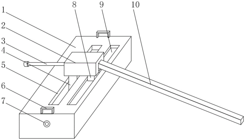
图1为园林坡面绿化结构的立体结构示意图。Fig. 1 is a three-dimensional structural schematic diagram of a greening structure on a slope of a garden.
图2为园林坡面绿化结构壳体正视图的剖视图。Fig. 2 is a sectional view of the front view of the shell of the garden slope greening structure.
图3为园林坡面绿化结构壳体侧视图的剖视图。Fig. 3 is a sectional view of a side view of the shell of the garden slope greening structure.
图4为园林坡面绿化结构图3中A处结构放大示意图。Fig. 4 is an enlarged schematic diagram of the structure at A in Fig. 3 of the greening structure on the slope of the garden.
图中:1、壳体;2、水箱;3、伸缩软管;4、控制板;5、通口;6、把手;7、轴承;8、滑块;9、滑槽;10、方管;11、螺纹杆;12、顶板;13、雾化喷头;14、螺纹孔;15、插钉;16、电机;17、加固环。In the figure: 1. Shell; 2. Water tank; 3. Telescopic hose; 4. Control panel; 5. Port; 6. Handle; 7. Bearing; 8. Slider; 9. Chute; 10. Square tube ; 11, threaded rod; 12, top plate; 13, atomizing nozzle; 14, threaded hole; 15, inserting nail; 16, motor; 17, reinforcement ring.
具体实施方式Detailed ways
在本实用新型的描述中,需要理解的是,术语“中心”、“纵向”、“横向”、“上”、“下”、“前”、“后”、“左”、“右”、“竖直”、“水平”、“顶”、“底”、“内”、“外”等指示的方位或位置关系为基于附图所示的方位或位置关系,仅是为了便于描述本实用新型和简化描述,而不是指示或暗示所指的装置或元件必须具有特定的方位、以特定的方位构造和操作,因此不能理解为对本实用新型的限制。此外,术语“第一”、“第二”等仅用于描述目的,而不能理解为指示或暗示相对重要性或者隐含指明所指示的技术特征的数量。由此,限定有“第一”、“第二”等的特征可以明示或者隐含地包括一个或者更多个该特征。在本实用新型的描述中,除非另有说明,“多个”的含义是两个或两个以上。In describing the present utility model, it should be understood that the terms "center", "longitudinal", "transverse", "upper", "lower", "front", "rear", "left", "right", The orientations or positional relationships indicated by "vertical", "horizontal", "top", "bottom", "inner", "outer", etc. are based on the orientation or positional relationships shown in the drawings, and are only for the convenience of describing the present invention. Novel and simplified descriptions do not indicate or imply that the device or element referred to must have a specific orientation, be constructed and operate in a specific orientation, and therefore should not be construed as limiting the utility model. In addition, the terms "first", "second", etc. are used for descriptive purposes only, and should not be understood as indicating or implying relative importance or implicitly specifying the quantity of the indicated technical features. Thus, a feature defined as "first", "second", etc. may expressly or implicitly include one or more of that feature. In the description of the present utility model, unless otherwise specified, "plurality" means two or more.
在本实用新型的描述中,需要说明的是,除非另有明确的规定和限定,术语“安装”、“相连”、“连接”应做广义理解,例如,可以是固定连接,也可以是可拆卸连接,或一体地连接;可以是机械连接,也可以是电连接;可以是直接相连,也可以通过中间媒介间接相连,可以是两个元件内部的连通。对于本领域的普通技术人员而言,可以通过具体情况理解上述术语在本实用新型中的具体含义。In the description of the present utility model, it should be noted that, unless otherwise clearly stipulated and limited, the terms "installation", "connection" and "connection" should be understood in a broad sense, for example, it can be a fixed connection or a flexible connection. Detachable connection, or integral connection; it can be mechanical connection or electrical connection; it can be direct connection or indirect connection through an intermediary, and it can be the internal communication of two components. Those of ordinary skill in the art can understand the specific meanings of the above terms in the present invention through specific situations.
下面将结合本实用新型实施例中的附图,对本实用新型实施例中的技术方案进行清楚、完整地描述,显然,所描述的实施例仅仅是本实用新型一部分实施例,而不是全部的实施例。基于本实用新型中的实施例,本领域普通技术人员在没有做出创造性劳动前提下所获得的所有其他实施例,都属于本实用新型保护的范围。The technical solutions in the embodiments of the present invention will be clearly and completely described below in conjunction with the accompanying drawings in the embodiments of the present invention. Obviously, the described embodiments are only part of the embodiments of the present invention, not all of them. example. Based on the embodiments of the present utility model, all other embodiments obtained by persons of ordinary skill in the art without making creative efforts belong to the scope of protection of the present utility model.
请参阅图1-4,本实用新型中,园林坡面绿化结构,包括壳体1,壳体1的上表面开设有通口5,通口5的内壁滑动连接有控制板4,控制板4的正面开设有螺纹孔14,壳体1的正面和壳体1的背面均固定镶嵌有轴承7,螺纹孔14的内壁螺纹连接有螺纹杆11,螺纹杆11的两端分别与两个轴承7的内圈固定连接,壳体1的背面固定连接有电机16,电机16的输出端与螺纹杆11的后端固定连接,控制板4的上表面固定连接有水箱2,水箱2的右侧面固定连通有方管10,方管10的底面固定连通有一组等距离排列的雾化喷头13,水箱2的左侧面固定连通有伸缩软管3。Please refer to Fig. 1-4, in the utility model, the garden slope greening structure includes a
壳体1的上方设有两个把手6,每个把手6的底面均与壳体1的底面固定连接,通过设有把手6可以拉动该装置,以便于将该装置进行搬动,壳体1的下方设有两组插钉15,每个插钉15的上表面均与壳体1的底面固定连接,通过设有插钉15可以增加插钉15的稳定性,防止该装置在使用时出现滑动,壳体1的上表面开设有滑槽9,滑槽9的内壁滑动连接有滑块8,滑块8的上表面与水箱2的底面固定连接,通过设有滑槽9和滑块8可以对该装置进行定位,防止水箱2在使用时出现松动。Two
电机16的外表面固定连接有加固环17,加固环17的正面与壳体1的背面固定连接,通过设有加固环17可以对电机16进行加固,防止电机16在使用时出现松动,水箱2的右侧面固定连接有顶板12,顶板12的上表面与方管10的底面固定连接,通过设有顶板12可以对方管10进行支撑,防止方管10出现变形。The outer surface of the
本实用新型的工作原理是:The working principle of the utility model is:
在使用时将该装置搬动至坡地上方,并且将伸缩软管3与水源进行连通,将该装置连接电源,通过开关对电机16进行控制,电机16带动螺纹杆14旋转,螺纹杆14利用与螺纹孔11的螺纹连接,使螺纹孔11带动控制板4移动,使控制板4推动水箱2移动,水箱2带动方管10进行移动,使雾化喷头13将水喷洒出现,对坡面上的绿植进行浇水。When in use, the device is moved to the top of the slope, and the telescopic hose 3 is communicated with the water source, the device is connected to the power supply, and the
对于本领域技术人员而言,显然本实用新型不限于上述示范性实施例的细节,而且在不背离本实用新型的精神或基本特征的情况下,能够以其他的具体形式实现本实用新型。因此,无论从哪一点来看,均应将实施例看作是示范性的,而且是非限制性的,本实用新型的范围由所附权利要求而不是上述说明限定,因此旨在将落在权利要求的等同要件的含义和范围内的所有变化囊括在本实用新型内。不应将权利要求中的任何附图标记视为限制所涉及的权利要求。It is obvious to those skilled in the art that the present invention is not limited to the details of the above exemplary embodiments, and that the present invention can be implemented in other specific forms without departing from the spirit or essential features of the present invention. Therefore, no matter from all points of view, the embodiments should be regarded as exemplary and non-restrictive, and the scope of the present invention is defined by the appended claims rather than the above description, so it is intended to fall within the scope of the claims All changes within the meaning and range of equivalents of the required elements are included in the present invention. Any reference sign in a claim should not be construed as limiting the claim concerned.
此外,应当理解,虽然本说明书按照实施方式加以描述,但并非每个实施方式仅包含一个独立的技术方案,说明书的这种叙述方式仅仅是为清楚起见,本领域技术人员应当将说明书作为一个整体,各实施例中的技术方案也可以经适当组合,形成本领域技术人员可以理解的其他实施方式。In addition, it should be understood that although this specification is described according to implementation modes, not each implementation mode only includes an independent technical solution, and this description in the specification is only for clarity, and those skilled in the art should take the specification as a whole , the technical solutions in the various embodiments can also be properly combined to form other implementations that can be understood by those skilled in the art.
Claims (6)
Priority Applications (1)
| Application Number | Priority Date | Filing Date | Title |
|---|---|---|---|
| CN202320053978.9U CN219042507U (en) | 2023-01-09 | 2023-01-09 | Garden Slope Greening Structure |
Applications Claiming Priority (1)
| Application Number | Priority Date | Filing Date | Title |
|---|---|---|---|
| CN202320053978.9U CN219042507U (en) | 2023-01-09 | 2023-01-09 | Garden Slope Greening Structure |
Publications (1)
| Publication Number | Publication Date |
|---|---|
| CN219042507U true CN219042507U (en) | 2023-05-19 |
Family
ID=86318657
Family Applications (1)
| Application Number | Title | Priority Date | Filing Date |
|---|---|---|---|
| CN202320053978.9U Expired - Fee Related CN219042507U (en) | 2023-01-09 | 2023-01-09 | Garden Slope Greening Structure |
Country Status (1)
| Country | Link |
|---|---|
| CN (1) | CN219042507U (en) |
-
2023
- 2023-01-09 CN CN202320053978.9U patent/CN219042507U/en not_active Expired - Fee Related
Similar Documents
| Publication | Publication Date | Title |
|---|---|---|
| CN205567334U (en) | Gardens are with atomizing sprinkling irrigation equipment | |
| CN207428050U (en) | A kind of municipal administration gardens water injector | |
| CN216931227U (en) | Irrigation equipment for view afforestation of convenient regulation | |
| CN217591730U (en) | Watering machine is used in view gardens | |
| CN219660580U (en) | Extending type water-saving irrigation device | |
| CN118340007A (en) | Afforestation construction device and construction method | |
| CN116548284A (en) | A sprinkler device for gardens with adjustable spraying range | |
| CN217217712U (en) | A spray device for landscaping | |
| CN116122312A (en) | Ecological slope protection system | |
| CN216650804U (en) | Novel farmland irrigation device for hydraulic engineering | |
| CN218959698U (en) | Garden plant watering device with angle adjusting function | |
| CN209950038U (en) | Efficient spraying device for landscaping | |
| CN219046947U (en) | A sprinkler device for garden breeding | |
| CN219628532U (en) | An easily adjustable sprinkler irrigation device for landscaping | |
| CN210580366U (en) | Gardens irrigation equipment of adjustable spray range | |
| CN219108369U (en) | Afforestation spray cart | |
| CN217742587U (en) | Gardens maintenance is with spraying strutting arrangement | |
| CN218163855U (en) | A portable watering device for landscaping maintenance | |
| CN221930918U (en) | Gardens sprinkling irrigation equipment | |
| CN218789093U (en) | Watering device for afforestation | |
| CN206866151U (en) | Place flower stand in a kind of gardens | |
| CN221785126U (en) | A kind of insecticide spraying device for seedlings | |
| CN216492001U (en) | Agricultural land surface sprinkling irrigation device | |
| CN222302624U (en) | New forms of energy gardens spray set | |
| CN217722499U (en) | Afforestation plant diseases and insect pests environmental protection sprinkler |
Legal Events
| Date | Code | Title | Description |
|---|---|---|---|
| GR01 | Patent grant | ||
| GR01 | Patent grant | ||
| CF01 | Termination of patent right due to non-payment of annual fee | ||
| CF01 | Termination of patent right due to non-payment of annual fee |
Granted publication date: 20230519 |