CN219032964U - Steel form for bridge concrete - Google Patents
Steel form for bridge concrete Download PDFInfo
- Publication number
- CN219032964U CN219032964U CN202223471250.2U CN202223471250U CN219032964U CN 219032964 U CN219032964 U CN 219032964U CN 202223471250 U CN202223471250 U CN 202223471250U CN 219032964 U CN219032964 U CN 219032964U
- Authority
- CN
- China
- Prior art keywords
- template
- mounting
- installation
- mounting box
- steel
- Prior art date
- Legal status (The legal status is an assumption and is not a legal conclusion. Google has not performed a legal analysis and makes no representation as to the accuracy of the status listed.)
- Active
Links
- 229910000831 Steel Inorganic materials 0.000 title claims abstract description 39
- 239000010959 steel Substances 0.000 title claims abstract description 39
- 230000000712 assembly Effects 0.000 claims abstract description 7
- 238000000429 assembly Methods 0.000 claims abstract description 7
- 238000007789 sealing Methods 0.000 claims abstract description 5
- 238000009434 installation Methods 0.000 claims description 45
- 238000000034 method Methods 0.000 abstract description 2
- 238000003466 welding Methods 0.000 abstract description 2
- 238000006073 displacement reaction Methods 0.000 description 7
- 230000009286 beneficial effect Effects 0.000 description 1
- 238000010276 construction Methods 0.000 description 1
- 230000007547 defect Effects 0.000 description 1
- 238000010586 diagram Methods 0.000 description 1
- 230000000694 effects Effects 0.000 description 1
- 238000012986 modification Methods 0.000 description 1
- 230000004048 modification Effects 0.000 description 1
- 238000006467 substitution reaction Methods 0.000 description 1
- 239000002023 wood Substances 0.000 description 1
Images
Landscapes
- Bridges Or Land Bridges (AREA)
Abstract
The utility model discloses a steel template for bridge concrete, which comprises a first template, wherein a second template is arranged above the first template, sealing gaskets are fixedly arranged at the top of the first template and the bottom of the second template, mounting assemblies are respectively arranged on the outer walls of the two sides of the first template, and fixing assemblies are respectively arranged on the outer walls of the two sides of the second template. In the using process, the steel template for the concrete can be effectively assembled and disassembled, the phenomenon that the screw is difficult to unscrew due to the fact that the bolt screw is required to be fixed in a bolt screw or welding mode when the existing steel template is installed is avoided, the working intensity of personnel loading and unloading operation is greatly reduced, the practicability of the steel template is improved, and convenience is brought to personnel operation.
Description
Technical Field
The utility model relates to the technical field of steel templates, in particular to a steel template for bridge concrete.
Background
The steel template is used for concrete pouring and forming, and besides the steel template, the steel template also comprises a wood template and the like. The steel forms are widely applied to constructional engineering due to the characteristics of repeated use, attractive concrete pouring and forming and the like, and the steel forms are required to be used for pouring concrete in bridge construction.
However, most of the existing concrete steel templates are poured by fixing two templates together through bolt screws or welding, when pouring is completed, the templates are separated by unscrewing the bolts, the process is very inconvenient, and the screws possibly have sliding wires to cause difficult disassembly, so that the loading and unloading efficiency of the steel templates is reduced, and the working strength of personnel is increased. For this purpose we propose a steel form for bridge concrete.
Disclosure of Invention
The utility model aims to solve the defects in the prior art, and provides a steel template for bridge concrete.
In order to achieve the above purpose, the present utility model adopts the following technical scheme:
the steel template for bridge concrete comprises a first template, a second template is arranged above the first template, sealing gaskets are fixedly installed at the top of the first template and the bottom of the second template, mounting assemblies are respectively arranged on the outer walls of two sides of the first template, and fixing assemblies are respectively arranged on the outer walls of two sides of the second template.
Preferably, the installation component includes the installation piece that sets up in first template one side, installation piece top one side runs through there is the mounting groove, the spout has all been seted up at the top of installation piece and the both sides that are located the mounting groove, the top of installation piece just is located the spout sliding connection has the slide bar, and two slide bars all are the type of falling L, two the pinion rack is installed jointly to the one end that the slide bar kept away from the spout, the bottom of pinion rack is connected with the gear through the latch meshing.
Preferably, the installation component still contains the commentaries on classics handle that sets up in the mounting groove, the inside of gear cup joints mutually with the outside of commentaries on classics handle, the one end that the gear was kept away from to the commentaries on classics handle runs through the installation piece through the axle sleeve and extends to installation piece one side outside, a second template lateral wall and be located the top fixed mounting of installation piece have the fixed block, jack has all been seted up in one side that the mounting groove was kept away from at fixed block top one side and installation piece top, the fixed block top is connected with the first inserted bar that is located the jack, the round hole has been seted up to the lower extreme of first inserted bar, the one end fixed mounting that the pinion rack is close to first inserted bar has the second inserted bar, the second inserted bar is pegged graft mutually with the round hole.
Preferably, the fixed subassembly includes the mounting box of installing at second template one side outer wall, the bottom of mounting box is the opening form, the inside of mounting box just is located opening part sliding connection has the mounting panel, the top fixedly connected with lifting rod of mounting panel, the one end that the mounting panel was kept away from to the lifting rod runs through the mounting box top and extends to the mounting box top.
Preferably, the fixed component further comprises a spring which is sleeved outside the lifting rod and is positioned inside the installation box, the top of the spring is fixedly connected with the inner top of the installation box, the bottom of the spring is fixedly connected with the top of the installation plate, a third inserting rod is fixedly installed in the middle of the bottom of the installation plate, a fixing plate is fixedly installed on the outer wall of one side of the first template and positioned below the installation box, a slot is formed in the middle of the fixing plate, and the lower end of the third inserting rod is inserted into the slot.
Preferably, a side wall of the mounting block far away from the gear is fixedly mounted with the outer wall of one side of the first template.
The steel template for bridge concrete has the beneficial effects that:
1. the first inserted link is inserted into the jack formed by the fixed block and the installation block, the gear is driven to rotate by rotating the rotating handle, so that the toothed plate connected with the latch teeth above the gear is shifted, the second inserted link is driven to be inserted into the round hole formed at the lower end of the first inserted link, the fixed block and the installation block are fixed, and a person can rapidly and conveniently assemble and disassemble the steel template.
2. Through upwards extracting the lifting rod, the mounting panel receives the pulling force of lifting rod at the inside upward displacement of mounting box and extrudees the spring, drives the third inserted bar simultaneously upwards in the lump, aligns slot Shi Songkai lifting rod, and spring elasticity is replied and is pushed back the mounting panel this moment to insert the fixed plate inside with the third inserted bar, and then accomplish fixedly to the other both sides of first template and second template, promote the loading and unloading convenience of steel template.
Drawings
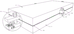
FIG. 1 is a schematic structural view of a steel form for bridge concrete according to the present utility model;
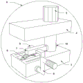
FIG. 2 is an enlarged schematic view of the A-site of the steel form for bridge concrete according to the present utility model;
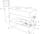
FIG. 3 is a schematic diagram showing the disassembly of a first insert rod of a steel form for bridge concrete according to the present utility model;
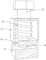
fig. 4 is a sectional view of the mounting box of the steel form for bridge concrete according to the present utility model.
In the figure: 1. a first template; 2. a second template; 3. a mounting block; 4. a fixed block; 5. a first plunger; 6. a rotating handle; 7. a toothed plate; 8. a gear; 9. a slide bar; 10. a second plunger; 11. a sealing gasket; 12. a lifting rod; 13. a spring; 14. a mounting box; 15. a mounting plate; 16. a third plunger; 17. and a fixing plate.
Detailed Description
The following description of the embodiments of the present utility model will be made clearly and completely with reference to the accompanying drawings, in which it is apparent that the embodiments described are only some embodiments of the present utility model, but not all embodiments.
In the description of the present utility model, it should be understood that the terms "upper," "lower," "front," "rear," "left," "right," "top," "bottom," "inner," "outer," and the like indicate or are based on the orientation or positional relationship shown in the drawings, merely to facilitate description of the present utility model and to simplify the description, and do not indicate or imply that the devices or elements referred to must have a specific orientation, be configured and operated in a specific orientation, and thus should not be construed as limiting the present utility model.
Referring to fig. 1-4, a steel template for bridge concrete comprises a first template 1, a second template 2 is arranged above the first template 1, sealing gaskets 11 are fixedly arranged at the top of the first template 1 and the bottom of the second template 2, mounting assemblies are respectively arranged on the outer walls of two sides of the first template 1, and a fixing assembly is respectively arranged on the outer walls of two sides of the second template 2.
The installation component includes the installation piece 3 that sets up in first template 1 one side, install piece 3 top one side and run through there is the mounting groove, the spout has all been seted up at the top of installation piece 3 and be located the both sides of mounting groove, the top of installation piece 3 and be located sliding connection in the spout have slide bar 9, two slide bars 9 all are the type of falling L, tooth plate 7 is installed jointly to the one end that the spout was kept away from to two slide bars 9, tooth plate 7's bottom is connected with gear 8 through the latch meshing, through setting up of tooth plate 7 and gear 8, make gear 8 rotate through changeing 6, drive tooth plate 7 displacement makes second inserted bar 10 displacement and inserts inside the 5 lower extreme of first inserted bar, and then accomplish fixedly to first inserted bar 5, also be fixed to installation piece 3 and fixed block 4.
The installation component still contains the commentaries on classics handle 6 that sets up in the mounting groove, the inside of gear 8 cup joints mutually with the outside of changeing handle 6, the one end that gear 8 was kept away from to changeing handle 6 runs through installation piece 3 through the axle sleeve and extends to installation piece 3 one side outsidely, the top fixed mounting that a second template 2 lateral wall just is located installation piece 3 has fixed block 4, fixed block 4 top one side is kept away from the one side of mounting groove with installation piece 3 top and has all run through and has been seted up the jack, fixed block 4 top is connected with the first inserted bar 5 that is located the jack, the round hole has been seted up to the lower extreme of first inserted bar 5, the pinion rack 7 is close to the one end fixed mounting of first inserted bar 5 has second inserted bar 10, second inserted bar 10 is pegged graft mutually with the round hole, through the setting of changeing handle 6, thereby the personnel of being convenient for rotate to change handle 6 and drive gear 8 and rotate.
The fixed subassembly includes the mounting box 14 of installing at second template 2 one side outer wall, the bottom of mounting box 14 is the opening form, the inside of mounting box 14 just is located opening part sliding connection has mounting panel 15, the top fixedly connected with lifting rod 12 of mounting panel 15, the one end that lifting rod 12 kept away from mounting panel 15 runs through mounting box 14 top and extends to mounting box 14 top, through lifting rod 12's setting, personnel draws lifting rod 12 and drives mounting panel 15 and produce vertical displacement to drive the displacement with third inserted bar 16, the personnel of being convenient for draw.
The fixed subassembly still includes the cover and establishes at the outside spring 13 that just is located mounting box 14 of lifting rod 12, the top of spring 13 and the interior top fixed connection of mounting box 14, the bottom of spring 13 and the top fixed connection of mounting panel 15, the bottom middle part fixed mounting of mounting panel 15 has third inserted bar 16, the fixed plate 17 of one side outer wall of first template 1 and the below fixed mounting of being located mounting box 14, the slot has been seted up at the middle part of fixed plate 17, the lower extreme and the slot of third inserted bar 16 peg graft mutually, through the setting of spring 13, when personnel draw lifting rod 12, drive mounting panel 15 and the upward displacement of third inserted bar 16, make the bottom of third inserted bar 16 dock with the slot in the fixed plate 17, loosen lifting rod 12 and make spring 13 receive elastic influence to resume with mounting panel 15 push back into inside fixed plate 17, accomplish the installation fixedly.
One side wall of the mounting block 3 far away from the gear 8 is fixedly mounted with one side outer wall of the first template 1, and the first template 1 and the second template 2 are conveniently and quickly mounted and fixed with each other through the arrangement of the mounting block 3.
The use principle and the advantages are that: this scheme is in the use, when installing the steel form, through with first template 1 with second template 2 alignment, insert fixed block 4 with later in the jack that installation piece 3 offered first inserted bar 5, drive gear 8 rotatory through rotating 6, make the tooth plate 7 displacement that tooth engagement was connected above the gear 8, slide bar 9 in the spout of tooth plate 7 both sides slide, play the spacing effect of support to tooth plate 7, thereby it is inside to drive second inserted bar 10 to insert the round hole that first inserted bar 5 lower extreme was offered, and then accomplish fixedly to fixed block 4 and installation piece 3, make personnel can swiftly conveniently load and unload the steel form.
Simultaneously, personnel upwards draw the lifting rod 12, mounting panel 15 receives the pulling force of lifting rod 12 and upwards displaces and extrudees spring 13 in mounting box 14 inside, simultaneously with the upward drive of third inserted bar 16 in the lump, when the lower extreme of aligning third inserted bar 16 and the slot of seting up on the fixed plate 17, loosen lifting rod 12, spring 13 elastic return pushes back mounting panel 15 this moment to insert inside the fixed plate 17 with third inserted bar 16, and then accomplish fixedly to the other both sides of first template 1 and second template 2, promote the loading and unloading convenience of steel template.
To sum up: this steel form for concrete can carry out quick loading and unloading to the steel form effectively, has avoided current steel form to need bolt screw or welded mode fixed and lead to the bolt smooth silk to unscrew the comparatively difficult phenomenon of screw when the installation to great alleviateed personnel loading and unloading operation's working strength, also promoted the practicality of steel form simultaneously, it is convenient that personnel's operation brings.
The foregoing is only a preferred embodiment of the present utility model, but the scope of the present utility model is not limited thereto, and any person skilled in the art, who is within the scope of the present utility model, should make equivalent substitutions or modifications according to the technical scheme of the present utility model and the inventive concept thereof, and should be covered by the scope of the present utility model.
Claims (6)
1. The steel template for bridge concrete comprises a first template (1), and is characterized in that a second template (2) is arranged above the first template (1), sealing gaskets (11) are fixedly installed at the top of the first template (1) and the bottom of the second template (2), mounting assemblies are respectively arranged on the outer walls of the two sides of the first template (1), and fixing assemblies are respectively arranged on the outer walls of the two sides of the second template (2).
2. The steel form for bridge concrete according to claim 1, wherein the installation component comprises an installation block (3) arranged on one side of the first form (1), an installation groove is penetrated on one side of the top of the installation block (3), sliding grooves are formed in the top of the installation block (3) and are positioned on two sides of the installation groove, sliding rods (9) are slidably connected in the sliding grooves and are arranged on the top of the installation block (3), the two sliding rods (9) are of inverted-L shapes, a toothed plate (7) is jointly installed at one end, far away from the sliding grooves, of each sliding rod (9), and gears (8) are connected to the bottom of the toothed plate (7) through latch meshing.
3. The steel form for bridge concrete according to claim 2, wherein the installation component further comprises a rotating handle (6) arranged in the installation groove, the inside of the gear (8) is sleeved with the outside of the rotating handle (6), one end of the rotating handle (6), far away from the gear (8), penetrates through the installation block (3) through the shaft sleeve and extends to the outside of one side of the installation block (3), a fixing block (4) is fixedly installed on one side wall of the second form (2) and above the installation block (3), jacks are formed in the top side of the fixing block (4) and the side, far away from the installation groove, of the installation block (3), a first inserting rod (5) positioned in the jacks is connected to the top of the fixing block (4), a round hole is formed in the lower end of the first inserting rod (5), a second inserting rod (10) is fixedly installed at one end, close to the first inserting rod (5), of the toothed plate (7), and the second inserting rod (10) is spliced with the round hole.
4. The steel form for bridge concrete according to claim 1, wherein the fixing component comprises a mounting box (14) mounted on one side outer wall of the second form (2), the bottom of the mounting box (14) is in an opening shape, a mounting plate (15) is slidably connected to the inside of the mounting box (14) and located at the opening, a lifting rod (12) is fixedly connected to the top of the mounting plate (15), and one end, far away from the mounting plate (15), of the lifting rod (12) extends to the upper portion of the mounting box (14) through the top of the mounting box (14).
5. The steel form for bridge concrete according to claim 4, wherein the fixing component further comprises a spring (13) sleeved outside the lifting rod (12) and located inside the mounting box (14), the top of the spring (13) is fixedly connected with the inner top of the mounting box (14), the bottom of the spring (13) is fixedly connected with the top of the mounting plate (15), a third inserting rod (16) is fixedly installed in the middle of the bottom of the mounting plate (15), a fixing plate (17) is fixedly installed on the outer wall of one side of the first form (1) and located below the mounting box (14), a slot is formed in the middle of the fixing plate (17), and the lower end of the third inserting rod (16) is spliced with the slot.
6. The steel form for bridge concrete according to claim 2, wherein a side wall of the mounting block (3) far from the gear (8) is fixedly mounted with a side outer wall of the first form (1).
Priority Applications (1)
| Application Number | Priority Date | Filing Date | Title |
|---|---|---|---|
| CN202223471250.2U CN219032964U (en) | 2022-12-26 | 2022-12-26 | Steel form for bridge concrete |
Applications Claiming Priority (1)
| Application Number | Priority Date | Filing Date | Title |
|---|---|---|---|
| CN202223471250.2U CN219032964U (en) | 2022-12-26 | 2022-12-26 | Steel form for bridge concrete |
Publications (1)
| Publication Number | Publication Date |
|---|---|
| CN219032964U true CN219032964U (en) | 2023-05-16 |
Family
ID=86288413
Family Applications (1)
| Application Number | Title | Priority Date | Filing Date |
|---|---|---|---|
| CN202223471250.2U Active CN219032964U (en) | 2022-12-26 | 2022-12-26 | Steel form for bridge concrete |
Country Status (1)
| Country | Link |
|---|---|
| CN (1) | CN219032964U (en) |
-
2022
- 2022-12-26 CN CN202223471250.2U patent/CN219032964U/en active Active
Similar Documents
| Publication | Publication Date | Title |
|---|---|---|
| CN113833254A (en) | Building template suitable for rapid assembly and use method thereof | |
| CN203649877U (en) | Lock box guide board screw fastening device | |
| CN112095581A (en) | Concrete pipe pile convenient to installation is dismantled | |
| CN216766368U (en) | Partition wall convenient to installation is dismantled | |
| CN220753202U (en) | Electric furnace transformer tank structure convenient to dismantle | |
| CN110872907B (en) | Split assembly type prefabricated steel frame building and mounting structure | |
| CN113622543A (en) | Assembly type building | |
| CN209379820U (en) | Smallclothes precast concrete reinforcing bar shaper | |
| CN112982939B (en) | High-stability attached lifting scaffold | |
| CN113202227B (en) | Wall body board convenient to installation for assembly type building | |
| CN204409423U (en) | Filling machinery on a kind of meat-processing | |
| CN221539708U (en) | Machining table for machining mechanical parts | |
| CN208413570U (en) | A kind of Cargo Lift being easily installed | |
| CN211762663U (en) | High-efficient drilling equipment of jewelry | |
| CN220848069U (en) | Building structure connecting piece | |
| CN219885467U (en) | Use stable lifting clamp | |
| CN219732430U (en) | Lattice curtain wall | |
| CN216195765U (en) | Unit curtain wall structure capable of being disassembled and assembled | |
| CN221255804U (en) | Assembled partition wall fossil fragments structure | |
| CN218453397U (en) | Semitrailer roof side beam structure | |
| CN221255827U (en) | Combined aluminum plate curtain wall | |
| CN218375272U (en) | Building template reinforcing member for concrete pouring | |
| CN222275756U (en) | Assembled integral type superposed frame structure | |
| CN218535215U (en) | Transmission assembly is used in packaging film production | |
| CN220725164U (en) | Assembled building foundation skeleton texture |
Legal Events
| Date | Code | Title | Description |
|---|---|---|---|
| GR01 | Patent grant | ||
| GR01 | Patent grant |