CN219032945U - Template support bracket for bridge construction - Google Patents
Template support bracket for bridge construction Download PDFInfo
- Publication number
- CN219032945U CN219032945U CN202222805545.2U CN202222805545U CN219032945U CN 219032945 U CN219032945 U CN 219032945U CN 202222805545 U CN202222805545 U CN 202222805545U CN 219032945 U CN219032945 U CN 219032945U
- Authority
- CN
- China
- Prior art keywords
- wall
- bridge construction
- rod
- base
- support bracket
- Prior art date
- Legal status (The legal status is an assumption and is not a legal conclusion. Google has not performed a legal analysis and makes no representation as to the accuracy of the status listed.)
- Active
Links
Images


Landscapes
- Bridges Or Land Bridges (AREA)
Abstract
本实用新型涉及桥梁建设技术领域,公开了一种桥梁建设施工用模板支撑托架,包括底座,底座的顶部外壁上设置有升降板,升降板的顶部外壁上铰接有支撑板块,升降板的顶部外壁上安装有连接框,连接框通过轴承连接有螺纹杆,升降板的顶部外壁上开设有滑槽,升降板通过滑槽滑动卡接有滑块,通过设置的螺纹杆、移动杆与连接杆,转动螺纹杆带动移动杆移动,使滑块通过滑槽移动,移动杆通过连接杆调节支撑板块的倾斜角度,从而便于对倾斜面进行支撑,电机输出端带动蜗杆转动,蜗杆带动蜗轮与第一皮带轮转动,第一皮带轮通过传动皮带带动第二皮带轮与齿轮转动,使得齿杆通过支撑框进行升降,从而便于对支撑板块的高度进行调节。
The utility model relates to the technical field of bridge construction, and discloses a formwork supporting bracket for bridge construction, comprising a base, a lifting plate is arranged on the top outer wall of the base, a supporting plate is hinged on the top outer wall of the lifting plate, and the top of the lifting plate A connecting frame is installed on the outer wall, and the connecting frame is connected with a threaded rod through a bearing. , turning the threaded rod drives the moving rod to move, so that the slider moves through the chute, the moving rod adjusts the inclination angle of the support plate through the connecting rod, so as to facilitate the support of the inclined surface, the output end of the motor drives the worm to rotate, and the worm drives the worm wheel and the first The belt pulley rotates, and the first belt pulley drives the second belt pulley and the gear to rotate through the transmission belt, so that the gear rod is lifted and lowered through the support frame, thereby facilitating the adjustment of the height of the support plate.
Description
技术领域technical field
本实用新型涉及桥梁建设技术领域,特别涉及一种桥梁建设施工用模板支撑托架。The utility model relates to the technical field of bridge construction, in particular to a formwork support bracket for bridge construction.
背景技术Background technique
模板支撑托架是在建筑上用于混凝土现浇施工的模板支撑结构,普遍采用钢或木梁拼装成模板托架,利用钢或木杆搭建成脚手架构成托架支撑,并配合钢模板进行混凝土施工。The formwork support bracket is a formwork support structure used for concrete cast-in-place construction in buildings. Steel or wooden beams are generally used to assemble formwork brackets, and steel or wooden poles are used to form scaffolding to form bracket supports, and concrete is carried out with steel formwork. construction.
经检索中国专利号CN215289725U公开了一种桥梁建设用施工模板支撑托架,包括底座,底座顶部的两侧均焊接有圆柱,圆柱的顶部焊接有圆管,圆管的外圈螺纹连接有螺纹管,圆管的内腔活动连接有第一液压缸,第一液压缸的顶部安装有伸缩杆,伸缩杆的顶部活动连接有矩形板,该桥梁建设用施工模板支撑托架,通过第二液压缸运转带动第二伸缩杆运动,第二伸缩杆运动带动垫块运动,把底座撑起来进行调平限位工作,通过第一液压缸运转带动伸缩杆运动,伸缩杆运动带动矩形板上下运动调节高度,从而解决了现阶段的桥梁施工模板支撑架采用螺栓连接,螺栓易丢失,同时还浪费时间和劳动力,同时路桥梁施工时模板支撑架不方便进行拆装工作,且材料容易掉落的问题。After retrieval, Chinese Patent No. CN215289725U discloses a construction template support bracket for bridge construction, including a base, a cylinder is welded on both sides of the top of the base, a round pipe is welded on the top of the round pipe, and a threaded pipe is threaded on the outer ring of the round pipe , the inner cavity of the round pipe is movably connected with the first hydraulic cylinder, and the top of the first hydraulic cylinder is installed with a telescopic rod, and the top of the telescopic rod is movably connected with a rectangular plate. The operation drives the movement of the second telescopic rod, the movement of the second telescopic rod drives the movement of the block, props up the base for leveling and limit work, the operation of the first hydraulic cylinder drives the movement of the telescopic rod, and the movement of the telescopic rod drives the rectangular plate to move up and down to adjust the height , so as to solve the problem that the formwork support frame of the bridge construction at the present stage is connected by bolts, the bolts are easy to lose, and time and labor are wasted.
现有技术中模板支撑托架使用时,不便对模板的角度进行调节,缺少倾斜面支撑的效果,基于此,本实用新型设计了一种桥梁建设施工用模板支撑托架,以解决上述问题。When the formwork support bracket in the prior art is used, it is inconvenient to adjust the angle of the formwork and lacks the effect of inclined surface support. Based on this, the utility model designs a formwork support bracket for bridge construction to solve the above problems.
实用新型内容Utility model content
本实用新型的目的在于提供一种桥梁建设施工用模板支撑托架,以解决上述背景技术中提出不便对模板的角度进行调节的问题。The purpose of this utility model is to provide a formwork support bracket for bridge construction, to solve the problem of inconvenient adjustment of the angle of the formwork in the above-mentioned background technology.
为实现上述目的,本实用新型提供如下技术方案:一种桥梁建设施工用模板支撑托架,包括底座,所述底座的顶部外壁上设置有升降板,所述升降板的顶部外壁上铰接有支撑板块,所述升降板的顶部外壁上安装有连接框,所述连接框通过轴承连接有螺纹杆,所述升降板的顶部外壁上开设有滑槽,所述升降板通过所述滑槽滑动卡接有滑块,所述滑块的顶部外壁上安装有移动杆,所述移动杆与所述螺纹杆螺纹连接,所述移动杆的两端通过轴承分别连接有连接杆,所述连接杆的一端与所述支撑板块相铰接。In order to achieve the above purpose, the utility model provides the following technical solutions: a formwork support bracket for bridge construction, including a base, a lifting plate is arranged on the top outer wall of the base, and a support is hinged on the top outer wall of the lifting plate A connecting frame is installed on the top outer wall of the lifting plate, the connecting frame is connected with a threaded rod through a bearing, a chute is opened on the top outer wall of the lifting plate, and the lifting plate slides through the chute A slider is connected, and a moving rod is installed on the top outer wall of the slider, and the moving rod is threadedly connected with the threaded rod, and the two ends of the moving rod are respectively connected with connecting rods through bearings, and the connecting rods One end is hinged with the support plate.
作为优选方案,所述螺纹杆的一端固定连接有转盘。As a preferred solution, one end of the threaded rod is fixedly connected with a turntable.
作为优选方案,所述底座的顶部外壁上安装有支撑框,所述支撑框的内部滑动卡接有齿杆,所述齿杆的顶端与所述升降板相连接。As a preferred solution, a support frame is installed on the top outer wall of the base, and a gear rod is slidably engaged inside the support frame, and the top end of the gear rod is connected with the lifting plate.
作为优选方案,所述底座的顶部外壁上固定安装有支撑架,所述支撑架的底部外壁上安装有电机,所述电机的输出端连接有蜗杆,所述支撑架的顶部外壁上通过轴承连接有转动轴,所述转动轴的侧壁上分别安装有蜗轮与第一皮带轮,所述蜗轮与所述蜗杆啮合连接,所述底座的顶部外壁上通过轴承连接有传动轴,所述传动轴的一端连接有第二皮带轮,所述第二皮带轮通过传动皮带与所述第一皮带轮相连接,所述传动轴的侧壁上安装有齿轮,所述齿轮与所述齿杆啮合连接。As a preferred solution, a support frame is fixedly installed on the top outer wall of the base, a motor is installed on the bottom outer wall of the support frame, a worm is connected to the output end of the motor, and the top outer wall of the support frame is connected by a bearing. There is a rotating shaft, a worm wheel and a first pulley are respectively installed on the side wall of the rotating shaft, the worm wheel is engaged with the worm, and the top outer wall of the base is connected with a transmission shaft through a bearing. One end is connected with a second pulley, the second pulley is connected with the first pulley through a transmission belt, a gear is installed on the side wall of the transmission shaft, and the gear is engaged with the gear rod.
作为优选方案,所述支撑框的内壁上开设有辅助槽,所述齿杆的两侧壁上分别安装有滑杆,所述滑杆与所述辅助槽滑动卡接。As a preferred solution, auxiliary grooves are provided on the inner wall of the support frame, sliding bars are installed on the two side walls of the gear rod respectively, and the sliding bars are slidably engaged with the auxiliary grooves.
作为优选方案,所述底座的底部外壁上安装有自锁万向轮。As a preferred solution, self-locking universal wheels are installed on the bottom outer wall of the base.
本实用新型的技术效果和优点:Technical effect and advantage of the present utility model:
1、通过设置的螺纹杆、移动杆与连接杆,转动螺纹杆带动移动杆移动,使滑块通过滑槽移动,移动杆通过连接杆调节支撑板块的倾斜角度,从而便于对倾斜面进行支撑。1. Through the set threaded rod, moving rod and connecting rod, turning the threaded rod drives the moving rod to move, so that the slider moves through the chute, and the moving rod adjusts the inclination angle of the supporting plate through the connecting rod, so as to facilitate the support of the inclined surface.
2、通过设置的电机、蜗杆、蜗轮、第一皮带轮、第二皮带轮、齿轮、支撑框与齿杆,电机输出端带动蜗杆转动,蜗杆带动蜗轮与第一皮带轮转动,第一皮带轮通过传动皮带带动第二皮带轮与齿轮转动,使得齿杆通过支撑框进行升降,从而便于对支撑板块的高度进行调节。2. Through the set motor, worm, worm wheel, first pulley, second pulley, gear, support frame and gear rod, the output end of the motor drives the worm to rotate, the worm drives the worm wheel and the first pulley to rotate, and the first pulley is driven by the transmission belt The rotation of the second belt pulley and the gear makes the gear bar go up and down through the support frame, thereby facilitating the adjustment of the height of the support plate.
附图说明Description of drawings
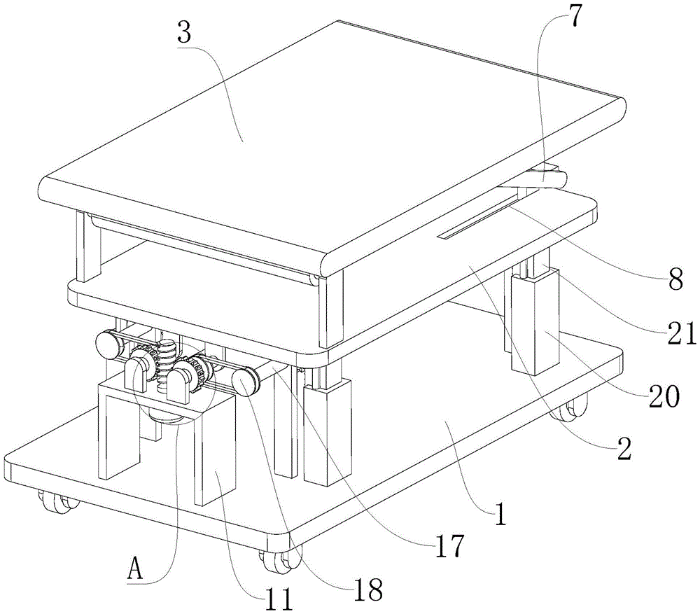
图1为本实用新型整体立体结构的示意图。Fig. 1 is a schematic diagram of the overall three-dimensional structure of the utility model.
图2为本实用新型立体结构的示意图。Fig. 2 is a schematic diagram of the three-dimensional structure of the utility model.
图3为本实用新型图1中A处放大结构的示意图。Fig. 3 is a schematic diagram of the enlarged structure at A in Fig. 1 of the present utility model.
图中:1、底座;2、升降板;3、支撑板块;4、连接框;5、螺纹杆;6、移动杆;7、连接杆;8、滑槽;9、滑块;10、转盘;11、支撑架;12、电机;13、蜗杆;14、转动轴;15、蜗轮;16、第一皮带轮;17、传动轴;18、第二皮带轮;19、齿轮;20、支撑框;21、齿杆;22、滑杆;23、辅助槽。In the figure: 1. Base; 2. Lifting plate; 3. Supporting plate; 4. Connecting frame; 5. Threaded rod; 6. Moving rod; 7. Connecting rod; 8. Chute; 9. Slider; 10.
具体实施方式Detailed ways
下面将结合本实用新型实施例中的附图,对本实用新型实施例中的技术方案进行清楚、完整地描述,显然,所描述的实施例仅仅是本实用新型一部分实施例,而不是全部的实施例。基于本实用新型中的实施例,本领域普通技术人员在没有做出创造性劳动前提下所获得的所有其他实施例,都属于本实用新型保护的范围。The technical solutions in the embodiments of the present invention will be clearly and completely described below in conjunction with the accompanying drawings in the embodiments of the present invention. Obviously, the described embodiments are only part of the embodiments of the present invention, not all of them. example. Based on the embodiments of the present utility model, all other embodiments obtained by persons of ordinary skill in the art without making creative efforts belong to the scope of protection of the present utility model.
本实用新型提供了如图1-3所示的一种桥梁建设施工用模板支撑托架,包括底座1,底座1的底部外壁上安装有自锁万向轮,底座1通过自锁万向轮便于灵活移动,底座1的顶部外壁上设置有升降板2,升降板2的顶部外壁上铰接有支撑板块3,升降板2的顶部外壁上安装有连接框4,连接框4通过轴承连接有螺纹杆5,升降板2的顶部外壁上开设有滑槽8,升降板2通过滑槽8滑动卡接有滑块9,滑块9的顶部外壁上安装有移动杆6,移动杆6与螺纹杆5螺纹连接,移动杆6的两端通过轴承分别连接有连接杆7,连接杆7的一端与支撑板块3相铰接,转动螺纹杆5带动移动杆6移动,使得滑块9通过滑槽8滑动,移动杆6通过连接杆7带动支撑板块3调节倾斜角度,对倾斜面进行支撑。The utility model provides a formwork support bracket for bridge construction as shown in Figure 1-3, including a
在本实施例中,螺纹杆5的一端固定连接有转盘10,通过设置的转盘10便于转动螺纹杆5。In this embodiment, one end of the threaded
在本实施例中,底座1的顶部外壁上安装有支撑框20,支撑框20的内部滑动卡接有齿杆21,齿杆21的顶端与升降板2相连接,底座1的顶部外壁上固定安装有支撑架11,支撑架11的底部外壁上安装有电机12,电机12的输出端连接有蜗杆13,支撑架11的顶部外壁上通过轴承连接有转动轴14,转动轴14的侧壁上分别安装有蜗轮15与第一皮带轮16,蜗轮15与蜗杆13啮合连接,底座1的顶部外壁上通过轴承连接有传动轴17,传动轴17的一端连接有第二皮带轮18,第二皮带轮18通过传动皮带与第一皮带轮16相连接,传动轴17的侧壁上安装有齿轮19,齿轮19与齿杆21啮合连接,电机12输出端带动蜗杆13转动,蜗杆13通过蜗轮15带动转动轴14转动,转动轴14带动第一皮带轮16转动,第一皮带轮16通过传动皮带带动第二皮带轮18与传动轴17转动,传动轴17带动齿轮19转动,齿杆21通过支撑框20升降,调节支撑板块3的高度,支撑框20的内壁上开设有辅助槽23,齿杆21的两侧壁上分别安装有滑杆22,滑杆22与辅助槽23滑动卡接,齿杆21升降时带动滑杆22通过辅助槽23滑动,提升其稳定性。In this embodiment, a
本实用工作原理:本实用新型为一种桥梁建设施工用模板支撑托架,首先,使用时底座1移动至使用位置,电机12输出端驱动蜗杆13转动,蜗杆13通过蜗轮15带动转动轴14转动,转动轴14带动第一皮带轮16转动,第一皮带轮16通过传动皮带带动第二皮带轮18与传动轴17转动,传动轴17带动齿轮19转动,使得齿杆21通过支撑框20升降,调节支撑板块3的高度。The working principle of the utility model: the utility model is a formwork support bracket for bridge construction. First, when in use, the
通过转盘10带动螺纹杆5转动,使得移动杆6带动滑块9通过滑槽8滑动,移动杆6通过连接杆7带动支撑板块3调节倾斜角度,对倾斜面进行支撑。The
最后应说明的是:以上所述仅为本实用新型的优选实施例而已,并不用于限制本实用新型,尽管参照前述实施例对本实用新型进行了详细的说明,对于本领域的技术人员来说,其依然可以对前述各实施例所记载的技术方案进行修改,或者对其中部分技术特征进行等同替换,凡在本实用新型的精神和原则之内,所作的任何修改、等同替换、改进等,均应包含在本实用新型的保护范围之内。Finally, it should be noted that: the above is only a preferred embodiment of the utility model, and is not intended to limit the utility model, although the utility model has been described in detail with reference to the foregoing embodiments, for those skilled in the art , it can still modify the technical solutions recorded in the foregoing embodiments, or perform equivalent replacements on some of the technical features. Any modifications, equivalent replacements, improvements, etc. made within the spirit and principles of the present utility model, All should be included within the protection scope of the present utility model.
Claims (6)
Priority Applications (1)
| Application Number | Priority Date | Filing Date | Title |
|---|---|---|---|
| CN202222805545.2U CN219032945U (en) | 2022-10-24 | 2022-10-24 | Template support bracket for bridge construction |
Applications Claiming Priority (1)
| Application Number | Priority Date | Filing Date | Title |
|---|---|---|---|
| CN202222805545.2U CN219032945U (en) | 2022-10-24 | 2022-10-24 | Template support bracket for bridge construction |
Publications (1)
| Publication Number | Publication Date |
|---|---|
| CN219032945U true CN219032945U (en) | 2023-05-16 |
Family
ID=86316139
Family Applications (1)
| Application Number | Title | Priority Date | Filing Date |
|---|---|---|---|
| CN202222805545.2U Active CN219032945U (en) | 2022-10-24 | 2022-10-24 | Template support bracket for bridge construction |
Country Status (1)
| Country | Link |
|---|---|
| CN (1) | CN219032945U (en) |
Cited By (1)
| Publication number | Priority date | Publication date | Assignee | Title |
|---|---|---|---|---|
| CN116572380A (en) * | 2023-04-04 | 2023-08-11 | 中交第二公路工程局有限公司 | An auxiliary device for the construction of the distribution beam at the bottom of the bridge prefabricated beam and its use method |
-
2022
- 2022-10-24 CN CN202222805545.2U patent/CN219032945U/en active Active
Cited By (1)
| Publication number | Priority date | Publication date | Assignee | Title |
|---|---|---|---|---|
| CN116572380A (en) * | 2023-04-04 | 2023-08-11 | 中交第二公路工程局有限公司 | An auxiliary device for the construction of the distribution beam at the bottom of the bridge prefabricated beam and its use method |
Similar Documents
| Publication | Publication Date | Title |
|---|---|---|
| CN215594899U (en) | Supporting template for constructional engineering | |
| CN214218088U (en) | A hydraulic lifting platform for fully mechanized coal mining face | |
| CN218881573U (en) | Civil engineering template bearing structure | |
| CN209958773U (en) | Formwork removing tool for floor aluminum alloy building formwork | |
| CN217500252U (en) | Supporting and reinforcing structure of deep foundation pit | |
| CN221798449U (en) | A device for checking the lowering point of a pile foundation reinforcement cage | |
| CN210685317U (en) | Construction platform for building | |
| CN219471492U (en) | A building construction support | |
| CN223368893U (en) | Building material processing device for water conservancy project construction | |
| CN221591993U (en) | Floor slab concrete pouring device | |
| CN217840852U (en) | Aluminum alloy template wallboard bottom regulator | |
| CN222184092U (en) | Height-adjustable sliding support structure | |
| CN223648997U (en) | An adjustable-angle hinged structure for the left and right frames of engineering machinery | |
| CN219031590U (en) | Underframe for tower crane | |
| CN223991346U (en) | Rock-soil foundation pit supporting enclosure wall | |
| CN219365427U (en) | Formwork support device for construction engineering | |
| CN217734823U (en) | A building formwork with support components | |
| CN219754530U (en) | Tunnel construction platform | |
| CN221703292U (en) | A new type of civil engineering support structure | |
| CN221056486U (en) | A fixing base for power transmission and transformation engineering detection | |
| CN220790500U (en) | Safety support frame for high-rise building | |
| CN217680362U (en) | Anti-drop scaffolding for decoration | |
| CN221920281U (en) | Plate buckle type steel pipe supporting structure for template | |
| CN219363063U (en) | Rotary chassis of full-rotary crane | |
| CN221896167U (en) | A safety frame for construction site |
Legal Events
| Date | Code | Title | Description |
|---|---|---|---|
| GR01 | Patent grant | ||
| GR01 | Patent grant |