CN219025720U - Mechanical pushing device - Google Patents
Mechanical pushing device Download PDFInfo
- Publication number
- CN219025720U CN219025720U CN202222671258.7U CN202222671258U CN219025720U CN 219025720 U CN219025720 U CN 219025720U CN 202222671258 U CN202222671258 U CN 202222671258U CN 219025720 U CN219025720 U CN 219025720U
- Authority
- CN
- China
- Prior art keywords
- groove
- pushing device
- sides
- screw
- fixedly connected
- Prior art date
- Legal status (The legal status is an assumption and is not a legal conclusion. Google has not performed a legal analysis and makes no representation as to the accuracy of the status listed.)
- Expired - Fee Related
Links
Images

Landscapes
- Press Drives And Press Lines (AREA)
Abstract
本实用新型公开了一种机械式顶推装置,包括基座和固定连接在基座上的模具主体,模具主体的顶部设有用于对工件进行成型的模型槽,所述模具主体的底部开设有活动槽,活动槽两侧内壁的底部均开设有凹槽,基座的顶部还开设有横向槽;所述活动槽内活动安装有升降顶板,升降顶板的顶部两侧均固定连接有用于对工件进行顶推的顶推杆;所述升降顶板的底部中央固定安装有顶块,顶块的两侧底部均转动连接有倾斜设置的转动连杆。该机械式顶推装置,通过机械操作,可以方便快速的将工件从模具中取出来,避免了以往还需要通过手动顶推取料的麻烦,不仅省时省力,而且大大降低了人们的劳力消耗,有利于提高整体的工作效率。

The utility model discloses a mechanical pushing device, which comprises a base and a mold main body fixedly connected to the base. The top of the mold main body is provided with a mold groove for molding workpieces, and the bottom of the mold main body is provided with Movable groove, the bottom of the inner wall on both sides of the movable groove is provided with grooves, and the top of the base is also provided with a transverse groove; a lifting top plate is installed in the movable groove, and both sides of the top of the lifting top plate are fixedly connected. A push rod for pushing; a top block is fixedly installed in the center of the bottom of the lifting top plate, and the bottoms of both sides of the top block are rotatably connected with rotating connecting rods arranged obliquely. The mechanical pushing device can conveniently and quickly take out the workpiece from the mold through mechanical operation, avoiding the trouble of manually pushing and taking out materials in the past, which not only saves time and effort, but also greatly reduces people's labor consumption , which is conducive to improving the overall work efficiency.
Description
技术领域technical field
本实用新型涉及机械技术领域,尤其涉及一种机械式顶推装置。The utility model relates to the technical field of machinery, in particular to a mechanical pushing device.
背景技术Background technique
目前,在一些机械模具加工过程中,常常使用到顶推装置来将加工好的工件进行脱模顶推出来。如现有技术CN103302818B公开了一种光学构件模具脱模顶推装置,该模具包括有母模仁组及公模仁组,该顶推装置设于该公模仁组上,该顶推装置包括有第一座板、第一顶推块、第二座板、第二顶推块、底板及推动件组。该推动件组的第一顶推块及第二顶推块可被推动件组带动而能作往复的作动,而可避免该光学构件脱离模具时被公模仁组刮伤,藉此来提升该光学构件的良率及提升该模具的使用功效。At present, in some mechanical mold processing processes, a pusher device is often used to eject the processed workpiece from the mold. For example, the prior art CN103302818B discloses a demoulding and pushing device for an optical component mold. The mold includes a female mold core group and a male mold core group. The pushing device is arranged on the male mold core group. The pushing device includes There are a first seat plate, a first push block, a second seat plate, a second push block, a bottom plate and a push piece group. The first push block and the second push block of the pusher group can be driven by the pusher group to perform reciprocating action, which can prevent the optical component from being scratched by the male mold core group when it leaves the mold, thereby Improve the yield rate of the optical component and improve the use efficiency of the mold.
而在一些机械模具冲压加工过程中,仍然通过手动顶推工件的方式来取料,这样对于冲压完毕的工件从模具腔室内进行取出不仅较为费力,而且会消耗人体的大量消耗,影响整体的工作效率。因此有必要提出一种机械式顶推装置来解决上述取料困难的问题。In the stamping process of some mechanical molds, the material is still retrieved by manually pushing the workpiece, so that it is not only laborious to remove the stamped workpiece from the mold cavity, but also consumes a lot of human body consumption, affecting the overall work. efficiency. Therefore it is necessary to propose a mechanical pushing device to solve the above-mentioned difficult problem of taking out materials.
实用新型内容Utility model content
本实用新型的目的是为了解决现有技术中存在的缺点,而提出的一种机械式顶推装置。The purpose of the utility model is to solve the shortcomings in the prior art, and propose a mechanical pushing device.
为了实现上述目的,本实用新型采用了如下技术方案:In order to achieve the above object, the utility model adopts the following technical solutions:
一种机械式顶推装置,包括基座和固定连接在基座上的模具主体,模具主体的顶部设有用于对工件进行成型的模型槽,所述模具主体的底部开设有活动槽,活动槽两侧内壁的底部均开设有凹槽,基座的顶部还开设有横向槽;所述活动槽内活动安装有升降顶板,升降顶板的顶部两侧均固定连接有用于对工件进行顶推的顶推杆;A mechanical pushing device, comprising a base and a mold body fixedly connected to the base, the top of the mold body is provided with a mold groove for molding a workpiece, the bottom of the mold body is provided with a movable groove, and the movable groove There are grooves on the bottom of the inner walls on both sides, and a transverse groove on the top of the base; a lifting top plate is installed in the movable groove, and both sides of the top of the lifting top plate are fixedly connected with a top for pushing the workpiece. putter;
所述升降顶板的底部中央固定安装有顶块,顶块的两侧底部均转动连接有倾斜设置的转动连杆,两个转动连杆的倾斜底端均转动连接有移动架,且两个移动架的底部均沿水平方向滑动安装于横向槽的底部内壁上;横向槽底部内壁的中央还固定安装有安装架,安装架的顶部固定安装有电机,电机的输出端转动贯穿至安装架内并固定连接有蜗杆,蜗杆上啮合有蜗轮,蜗轮上固定套接有丝杆,丝杆的两端分别贯穿至安装架的外侧并转动安装于横向槽的两侧内壁上,且丝杆贯穿于移动架并与移动架通过螺纹传动连接。The top block is fixedly installed in the center of the bottom of the lifting top plate, and the bottoms on both sides of the top block are rotatably connected with rotating connecting rods arranged obliquely. The bottom of the frame is slidingly installed on the bottom inner wall of the transverse groove along the horizontal direction; the center of the bottom inner wall of the transverse groove is also fixedly installed with a mounting frame, and the top of the mounting frame is fixedly mounted with a motor. The output end of the motor rotates through the mounting frame and The worm is fixedly connected, the worm is meshed with a worm wheel, and the worm wheel is fixedly sleeved with a screw. The two ends of the screw penetrate to the outside of the mounting frame and are rotatably installed on the inner walls of both sides of the transverse groove, and the screw runs through the moving The frame is connected with the mobile frame through screw transmission.
优选的,所述移动架上固定套接有丝杆螺母,且丝杆贯穿于丝杆螺母并与丝杆螺母螺纹连接。Preferably, a screw nut is fixedly sleeved on the moving frame, and the screw rod passes through the screw nut and is threadedly connected with the screw nut.
优选的,位于安装架两侧的丝杆上分别设置有外螺纹,且丝杆上的两个外螺纹的螺旋方向相反设置。Preferably, external threads are respectively provided on the screw rods located on both sides of the mounting frame, and the helical directions of the two external threads on the screw rods are set in opposite directions.
优选的,所述移动架的底部固定连接有第一滑块,横向槽的底部内壁上设有第一滑槽,且第一滑块滑动安装于第一滑槽内。Preferably, the bottom of the moving frame is fixedly connected with a first sliding block, the bottom inner wall of the transverse groove is provided with a first sliding slot, and the first sliding block is slidably installed in the first sliding slot.
优选的,所述升降顶板的两端均固定连接有第二滑块,活动槽的两侧内壁上均设有第二滑槽,且第二滑块沿竖直方向滑动安装于第二滑槽内。Preferably, both ends of the lifting top plate are fixedly connected with second sliders, and the inner walls of both sides of the movable groove are provided with second sliders, and the second sliders are slidably installed in the second sliders along the vertical direction Inside.
优选的,所述活动槽的顶部内壁上开设有收纳孔,且顶推杆的顶端活动设于收纳孔内。Preferably, a storage hole is opened on the top inner wall of the movable groove, and the top end of the push rod is movably arranged in the storage hole.
与现有技术相比,本实用新型的有益效果是:Compared with the prior art, the beneficial effects of the utility model are:
本实用新型中,通过电机、蜗杆、蜗轮、丝杆、移动架、丝杆螺母、外螺纹的配合,可以使两个移动架各自通过丝杆螺母在丝杆的两个外螺纹上进行相向螺纹传动,两个移动架相向移动时还通过两个转动连杆来带动顶块以及升降顶板和顶推杆向上移动,进而通过顶推杆的上移,从而可以将模型槽内的工件向上顶推出来;In the utility model, through the cooperation of the motor, the worm, the worm wheel, the screw, the moving frame, the screw nut, and the external thread, the two moving frames can respectively carry out opposite threads on the two external threads of the screw through the screw nut. Transmission, when the two moving frames move towards each other, the top block, the lifting top plate and the push rod are driven upward by two rotating connecting rods, and the workpiece in the model groove can be pushed upward by the upward movement of the push rod. come out;
最终,该机械式顶推装置,通过机械操作,可以方便快速的将工件从模具中取出来,避免了以往还需要通过手动顶推取料的麻烦,不仅省时省力,而且大大降低了人们的劳力消耗,有利于提高整体的工作效率。Finally, the mechanical pushing device can conveniently and quickly take the workpiece out of the mold through mechanical operation, avoiding the trouble of manually pushing and taking out materials in the past, which not only saves time and effort, but also greatly reduces people's labor costs. Labor consumption is conducive to improving the overall work efficiency.
附图说明Description of drawings
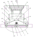
图1为本实用新型提出的一种机械式顶推装置的结构示意图;Fig. 1 is the structural representation of a kind of mechanical pushing device that the utility model proposes;
图2为本实用新型图1中A部分放大的结构示意图;Fig. 2 is the enlarged structural representation of part A in Fig. 1 of the utility model;
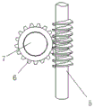
图3为本实用新型中蜗杆、蜗轮、丝杆之间的结构示意图。Fig. 3 is a structural diagram among the worm, the worm wheel and the screw mandrel in the utility model.
图中:1、模具主体;100、模型槽;101、活动槽;102、凹槽;103、收纳孔;2、基座;201、横向槽;3、安装架;4、电机;5、蜗杆;6、蜗轮;7、丝杆;701、外螺纹;8、移动架;801、丝杆螺母;9、转动连杆;10、顶块;11、升降顶板;12、顶推杆;13、第二滑块;14、第一滑块。In the figure: 1, mold main body; 100, model groove; 101, movable groove; 102, groove; 103, storage hole; 2, base; 201, transverse groove; 3, mounting frame; 4, motor; 5, worm ; 6, worm gear; 7, screw mandrel; 701, external thread; 8, mobile frame; 801, screw nut; 9, rotating connecting rod; 10, top block; 11, lifting top plate; The second slider; 14. The first slider.
具体实施方式Detailed ways
下面将结合本实用新型实施例中的附图,对本实用新型实施例中的技术方案进行清楚、完整地描述,显然,所描述的实施例仅仅是本实用新型一部分实施例,而不是全部的实施例。The technical solutions in the embodiments of the present invention will be clearly and completely described below in conjunction with the accompanying drawings in the embodiments of the present invention. Obviously, the described embodiments are only part of the embodiments of the present invention, not all of them. example.
参照图1-3,一种机械式顶推装置,包括基座2和固定连接在基座2上的模具主体1,模具主体1的顶部设有用于对工件进行成型的模型槽100,所述模具主体1的底部开设有活动槽101,活动槽101两侧内壁的底部均开设有凹槽102,基座2的顶部还开设有横向槽201;所述活动槽101内活动安装有升降顶板11,升降顶板11的顶部两侧均固定连接有用于对工件进行顶推的顶推杆12;Referring to Figures 1-3, a mechanical pushing device includes a
所述升降顶板11的底部中央固定安装有顶块10,顶块10的两侧底部均转动连接有倾斜设置的转动连杆9,两个转动连杆9的倾斜底端均转动连接有移动架8,且两个移动架8的底部均沿水平方向滑动安装于横向槽201的底部内壁上;横向槽201底部内壁的中央还固定安装有安装架3,安装架3的顶部固定安装有电机4,电机4的输出端转动贯穿至安装架3内并固定连接有蜗杆5,蜗杆5上啮合有蜗轮6,蜗轮6上固定套接有丝杆7,丝杆7的两端分别贯穿至安装架3的外侧并转动安装于横向槽201的两侧内壁上,且丝杆7贯穿于移动架8并与移动架8通过螺纹传动连接。The
在本实例中,所述移动架8上固定套接有丝杆螺母801,且丝杆7贯穿于丝杆螺母801并与丝杆螺母801螺纹连接;位于安装架3两侧的丝杆7上分别设置有外螺纹701,且丝杆7上的两个外螺纹701的螺旋方向相反设置。In this example, a
在本实例中,所述移动架8的底部固定连接有第一滑块14,横向槽201的底部内壁上设有第一滑槽,且第一滑块14滑动安装于第一滑槽内;所述升降顶板11的两端均固定连接有第二滑块13,活动槽101的两侧内壁上均设有第二滑槽,且第二滑块13沿竖直方向滑动安装于第二滑槽内。In this example, the bottom of the moving
在本实例中,所述活动槽101的顶部内壁上开设有收纳孔103,且顶推杆12的顶端活动设于收纳孔103内。In this example, a
工作原理:当需要对加工后的工件进行顶推取料时,通过电机4的输出端带动蜗杆5转动,蜗杆5转动时与蜗轮6啮合传动,这样可以带动蜗轮6转动,蜗轮6又带动丝杆7转动,丝杆7转动时与移动架8上的丝杆螺母801相对转动,由于丝杆7上的两个外螺纹701的螺旋方向相反设置,这样丝杆7转动时,可以使两个移动架8各自通过丝杆螺母801在丝杆7的两个外螺纹701上进行相向螺纹传动,两个移动架8相向移动时还通过两个转动连杆9来带动顶块10以及升降顶板11和顶推杆12向上移动,进而通过顶推杆12的上移,从而可以将模型槽100内的工件向上顶推出来,这样最终可以方便快速的将工件从模具中取出来,避免了以往还需要通过手动顶推取料的麻烦,不仅省时省力,而且大大降低了人们的劳力消耗,有利于提高整体的工作效率。Working principle: When it is necessary to push and take out the processed workpiece, the output end of the motor 4 drives the
以上所述,仅为本实用新型较佳的具体实施方式,但本实用新型的保护范围并不局限于此,任何熟悉本技术领域的技术人员在本实用新型揭露的技术范围内,根据本实用新型的技术方案及其实用新型构思加以等同替换或改变,都应涵盖在本实用新型的保护范围之内。The above is only a preferred embodiment of the utility model, but the scope of protection of the utility model is not limited thereto. The equivalent replacement or change of the new technical solution and the concept of the utility model shall be covered by the protection scope of the utility model.
Claims (6)
Priority Applications (1)
| Application Number | Priority Date | Filing Date | Title |
|---|---|---|---|
| CN202222671258.7U CN219025720U (en) | 2022-10-11 | 2022-10-11 | Mechanical pushing device |
Applications Claiming Priority (1)
| Application Number | Priority Date | Filing Date | Title |
|---|---|---|---|
| CN202222671258.7U CN219025720U (en) | 2022-10-11 | 2022-10-11 | Mechanical pushing device |
Publications (1)
| Publication Number | Publication Date |
|---|---|
| CN219025720U true CN219025720U (en) | 2023-05-16 |
Family
ID=86287575
Family Applications (1)
| Application Number | Title | Priority Date | Filing Date |
|---|---|---|---|
| CN202222671258.7U Expired - Fee Related CN219025720U (en) | 2022-10-11 | 2022-10-11 | Mechanical pushing device |
Country Status (1)
| Country | Link |
|---|---|
| CN (1) | CN219025720U (en) |
Cited By (2)
| Publication number | Priority date | Publication date | Assignee | Title |
|---|---|---|---|---|
| CN117046952A (en) * | 2023-07-31 | 2023-11-14 | 湖南长信建设集团有限公司 | Template for molding line aluminum alloy and application method thereof |
| CN118682024A (en) * | 2024-08-28 | 2024-09-24 | 中云汇(成都)物联科技有限公司 | A waterless alloy squat toilet stamping forming device |
-
2022
- 2022-10-11 CN CN202222671258.7U patent/CN219025720U/en not_active Expired - Fee Related
Cited By (2)
| Publication number | Priority date | Publication date | Assignee | Title |
|---|---|---|---|---|
| CN117046952A (en) * | 2023-07-31 | 2023-11-14 | 湖南长信建设集团有限公司 | Template for molding line aluminum alloy and application method thereof |
| CN118682024A (en) * | 2024-08-28 | 2024-09-24 | 中云汇(成都)物联科技有限公司 | A waterless alloy squat toilet stamping forming device |
Similar Documents
| Publication | Publication Date | Title |
|---|---|---|
| CN219838146U (en) | A mold ejection device for box shell processing | |
| CN213670632U (en) | Mould with maintain maintenance function | |
| CN221952278U (en) | A die-casting die for local thin-walled parts of automobile parts | |
| CN207982034U (en) | An easy-to-use metal stamping die | |
| CN216729094U (en) | Continuous extrusion die for non-ferrous metal alloy | |
| CN215359404U (en) | Trachea bandage mould hold-down mechanism | |
| CN213473231U (en) | Forming die conveying device for die machining | |
| CN210970022U (en) | A kind of mold for preparing display panel of home appliance | |
| CN223427354U (en) | Ultrathin soft magnetic ferrite core forming die | |
| CN215431257U (en) | Extrusion forming die | |
| CN221912947U (en) | Mould with anti-sticking material function | |
| CN212421917U (en) | Hydraulic ejection structure of pressurizing frame mold | |
| CN210820626U (en) | Forming die of aspirator bottom barrel | |
| CN221292426U (en) | Demoulding structure of mould | |
| CN217370062U (en) | Metal handle production mold convenient for material taking | |
| CN215320397U (en) | Take back-off to form energy-saving injection mold of demoulding structure | |
| CN221697713U (en) | Injection mold of side core pulling structure | |
| CN220144592U (en) | A bending mold that facilitates demoulding | |
| CN213137901U (en) | Double-guide mechanism for metal product mold frame | |
| CN221872965U (en) | Manufacturing die for protective shell of card swiping machine | |
| CN217451818U (en) | Forming die is used in electric motor car wheel hub processing | |
| CN219338272U (en) | A cleaning device for mold production and processing | |
| CN222115753U (en) | A fast-discharging plastic mold | |
| CN220808304U (en) | Mould box convenient to wash | |
| CN218429648U (en) | Mould is used in desktop computer support plastic part processing |
Legal Events
| Date | Code | Title | Description |
|---|---|---|---|
| GR01 | Patent grant | ||
| GR01 | Patent grant | ||
| CF01 | Termination of patent right due to non-payment of annual fee | ||
| CF01 | Termination of patent right due to non-payment of annual fee |
Granted publication date: 20230516 |