CN219023697U - Filter for air inlet of air cylinder - Google Patents
Filter for air inlet of air cylinder Download PDFInfo
- Publication number
- CN219023697U CN219023697U CN202320763715.7U CN202320763715U CN219023697U CN 219023697 U CN219023697 U CN 219023697U CN 202320763715 U CN202320763715 U CN 202320763715U CN 219023697 U CN219023697 U CN 219023697U
- Authority
- CN
- China
- Prior art keywords
- box body
- filter
- filter element
- conveying
- fixed
- Prior art date
- Legal status (The legal status is an assumption and is not a legal conclusion. Google has not performed a legal analysis and makes no representation as to the accuracy of the status listed.)
- Expired - Fee Related
Links
- 238000007790 scraping Methods 0.000 claims abstract description 17
- XLYOFNOQVPJJNP-UHFFFAOYSA-N water Substances O XLYOFNOQVPJJNP-UHFFFAOYSA-N 0.000 claims description 4
- 239000012141 concentrate Substances 0.000 claims 3
- 239000000428 dust Substances 0.000 abstract description 29
- 238000001914 filtration Methods 0.000 abstract description 4
- 239000012530 fluid Substances 0.000 abstract description 2
- 238000009825 accumulation Methods 0.000 abstract 1
- CNQCVBJFEGMYDW-UHFFFAOYSA-N lawrencium atom Chemical compound [Lr] CNQCVBJFEGMYDW-UHFFFAOYSA-N 0.000 description 16
- 238000007789 sealing Methods 0.000 description 3
- 239000002250 absorbent Substances 0.000 description 2
- 238000000034 method Methods 0.000 description 2
- 230000004048 modification Effects 0.000 description 2
- 238000012986 modification Methods 0.000 description 2
- 230000009286 beneficial effect Effects 0.000 description 1
- 238000004140 cleaning Methods 0.000 description 1
- 238000005516 engineering process Methods 0.000 description 1
- 239000012535 impurity Substances 0.000 description 1
- 239000002184 metal Substances 0.000 description 1
- 230000035945 sensitivity Effects 0.000 description 1
- 239000000779 smoke Substances 0.000 description 1
Images
Landscapes
- Filtering Of Dispersed Particles In Gases (AREA)
Abstract
本实用新型公开了一种气缸进气用过滤器,涉及流体过滤技术领域。本实用新型包括输送箱体、连接架、集中斗和底盒体,输送箱体的下方设置有底盒体,底盒体内设置有吸水海绵,输送箱体的两侧位置对应地贯通开设有活动口,活动口内活动连接有连接架,连接架包括活动连接在活动口内的刮动结构,输送箱体的顶部固定有集中斗。本实用新型通过设置输送箱体、连接架、集中斗和底盒体,解决了气缸进气用过滤器容易在滤芯过滤面上发生积灰现象,且滤芯更换周期较短造成更换成本较高的问题,本实用新型的优点为:更方便地减少滤芯过滤面上的积灰,且可以延长滤芯更换周期。

The utility model discloses a filter for air intake of a cylinder, which relates to the technical field of fluid filtration. The utility model includes a conveying box body, a connecting frame, a concentration bucket and a bottom box body. A bottom box body is arranged below the conveying box body, and a water-absorbing sponge is arranged in the bottom box body. A connecting frame is movably connected in the movable port, and the connecting frame includes a scraping structure movably connected in the movable port, and a concentrating bucket is fixed on the top of the conveying box. The utility model solves the problem that the cylinder air intake filter is easy to accumulate dust on the filter surface of the filter element by setting the conveying box body, the connecting frame, the concentration bucket and the bottom box body, and the replacement cycle of the filter element is relatively short, resulting in high replacement costs. Problem, the utility model has the advantages of: more conveniently reducing the dust accumulation on the filter surface of the filter element, and prolonging the replacement cycle of the filter element.
Description
技术领域technical field
本实用新型属于流体过滤技术领域,特别是涉及一种气缸进气用过滤器。The utility model belongs to the technical field of fluid filtration, in particular to a filter for cylinder air intake.
背景技术Background technique
引导活塞在缸内进行直线往复运动的圆筒形金属机件。空气在发动机气缸中通过膨胀将热能转化为机械能,气体在压缩机气缸中接受活塞压缩而提高压力,涡轮机、旋转活塞式发动机等的壳体通常也称气缸,通过气缸驱动相应的阀门,可以控制烟道排烟,工作环境恶劣,因此气缸的工作回路中的空气在进气时,需要通过过滤器滤除空气中相应的杂质,但它在实际使用中仍存在以下弊端:A cylindrical metal part that guides the piston to perform linear reciprocating motion in the cylinder. The air in the engine cylinder converts heat energy into mechanical energy through expansion, and the gas is compressed by the piston in the compressor cylinder to increase the pressure. The casing of the turbine, rotary piston engine, etc. is usually also called the cylinder, and the corresponding valve is driven by the cylinder. The flue exhausts smoke, and the working environment is harsh. Therefore, when the air in the working circuit of the cylinder is taken in, it needs to filter out the corresponding impurities in the air through a filter, but it still has the following disadvantages in actual use:
气缸进气用过滤器在工作时,直接通过滤芯将空气进行过滤,在空气进行过滤后,会滤出较多的灰尘,当停机后,灰尘会在滤芯的过滤面上堆积,长时间使用后,造成滤芯过滤效率下降;When the cylinder intake filter is working, the air is directly filtered through the filter element. After the air is filtered, a lot of dust will be filtered out. When the machine is turned off, the dust will accumulate on the filter surface of the filter element. , resulting in a decrease in the filtration efficiency of the filter element;
气缸进气用过滤器在工作时,滤芯在使用一段时间后,滤芯整体的过滤性能显著下降,继续使用,会造成气缸工作气路中压力下降,影响气缸的工作灵敏度,需要更换滤芯,使用时更换滤芯的周期较短,更换滤芯的成本较高。When the filter for air intake of the cylinder is working, after the filter element has been used for a period of time, the overall filtering performance of the filter element will drop significantly. Continued use will cause the pressure in the working air circuit of the cylinder to drop, which will affect the working sensitivity of the cylinder, and the filter element needs to be replaced. The cycle of replacing the filter element is short, and the cost of replacing the filter element is relatively high.
实用新型内容Utility model content
本实用新型的目的在于提供一种气缸进气用过滤器,通过设置输送箱体、连接架、集中斗和底盒体,解决了气缸进气用过滤器容易在滤芯过滤面上发生积灰现象,且滤芯更换周期较短造成更换成本较高的问题。The purpose of the utility model is to provide a filter for air intake of a cylinder, which solves the problem that the air intake filter of a cylinder is easy to accumulate dust on the filter surface of the filter element by setting a conveying box, a connecting frame, a concentration bucket and a bottom box body , and the short replacement cycle of the filter element causes the problem of high replacement cost.
为解决上述技术问题,本实用新型是通过以下技术方案实现的:In order to solve the problems of the technologies described above, the utility model is achieved through the following technical solutions:
本实用新型为一种气缸进气用过滤器,包括输送箱体、连接架、集中斗和底盒体,所述输送箱体的下方设置有底盒体,所述底盒体内设置有吸水海绵,所述输送箱体的两侧位置对应地贯通开设有活动口,所述活动口内活动连接有连接架,所述连接架包括活动连接在活动口内的刮动结构,所述输送箱体的顶部固定有集中斗,工作时,通过输送箱体中的滤芯将经过其中的空气进行过滤,通过连接架在工作的时候,在输送箱体中运动,使得滤芯底部被刮动,滤芯底部滤出的灰尘导到底盒体中,被底盒体收集,通过集中斗将滤芯过滤后的空气导出。The utility model relates to a filter for air intake of a cylinder, comprising a conveying box, a connecting frame, a collecting bucket and a bottom box body, a bottom box is arranged below the conveying box, and a water-absorbing sponge is arranged in the bottom box , the two sides of the conveying box are correspondingly opened with movable openings, and a connecting frame is movably connected in the movable opening, and the connecting frame includes a scraping structure movably connected in the movable opening, and the top of the conveying box A concentrating bucket is fixed. When working, the air passing through it is filtered through the filter element in the conveying box. When the connecting frame is working, it moves in the conveying box, so that the bottom of the filter element is scraped, and the filtered out from the bottom of the filter element The dust is guided into the bottom box body, collected by the bottom box body, and the air filtered by the filter element is exported through the concentration bucket.
进一步地,所述输送箱体内壁的活动口上方固定有支撑框,所述支撑框上方的输送箱体内固定有滤芯,通过支撑框对滤芯提供一定地支撑。Further, a support frame is fixed above the movable opening on the inner wall of the delivery box, and a filter element is fixed in the delivery box above the support frame, and the filter element is provided with certain support by the support frame.
进一步地,所述滤芯一侧的输送箱体上方固定连通有输气管,所述输送箱体的底部固定有输送斗,所述输送斗的底部固定连通有输入方管,滤芯在工作时,通过输气管将高压空气导到输送箱体中,通过输入方管即将空气导到输送箱体中。Further, an air pipe is fixedly connected above the conveying box on one side of the filter element, a conveying bucket is fixed on the bottom of the conveying box, and an input square pipe is fixedly connected to the bottom of the conveying bucket. When the filter element is working, it passes through The air pipe guides the high-pressure air into the delivery box, and the air is guided into the delivery box through the input square pipe.
进一步地,所述刮动结构包括连接块和刮板,所述刮板活动连接在支撑框内,且刮板的两端固定有连接块,所述连接块分别活动连接在输送箱体两侧的活动口内,通过连接块使得刮动结构输送箱体活动连接,通过刮板将滤芯底部滤出的灰尘进行刮动。Further, the scraping structure includes a connection block and a scraper, the scraper is movably connected in the support frame, and the two ends of the scraper are fixed with connection blocks, and the connection blocks are respectively movably connected to both sides of the conveying box In the movable port of the filter, the scraping structure conveying box is flexibly connected through the connecting block, and the dust filtered out from the bottom of the filter element is scraped through the scraper.
进一步地,所述连接架还包括连接条和两个连接杆,两个所述连接块远离刮板的一端皆固定连接有连接条,两个所述连接条互相靠近一面远离刮动结构的一端共同固定有连接杆,连接架在工作时,通过连接条连接连接杆,通过拉动连接杆,带动整个连接架运动。Further, the connecting frame also includes a connecting bar and two connecting rods, the ends of the two connecting blocks away from the scraper are fixedly connected to the connecting bar, and the ends of the two connecting bars that are close to each other and away from the scraping structure A connecting rod is fixed together, and when the connecting frame is working, the connecting rod is connected through the connecting bar, and the whole connecting frame is driven to move by pulling the connecting rod.
进一步地,所述集中斗的底部固定有密封垫,所述密封垫固定连接在输送箱体内的上部,所述集中斗的顶部固定连通有输送壳,所述输送壳的顶端固定连通有输送管,集中斗通过密封垫增加与输送箱体之间的密封性。Further, the bottom of the concentration bucket is fixed with a gasket, and the gasket is fixedly connected to the upper part of the delivery box, the top of the concentration bucket is fixedly connected with a delivery shell, and the top end of the delivery shell is fixedly connected with a delivery pipe , The sealing between the concentrated bucket and the conveying box is increased through the gasket.
本实用新型具有以下有益效果:The utility model has the following beneficial effects:
本实用新型通过设置输送箱体和连接架,解决了气缸进气用过滤器容易在滤芯过滤面上发生积灰现象的问题,工作气路中的负压,使得输送壳中过滤后的空气被抽到气缸工作气路中,在停机后,滤芯底部滤出的灰尘落到输送斗中,通过输入方管导到底盒体中,拉动连接杆时,带动连接架整体在输送箱体中运动,通过刮板被带动运动,将滤芯底部滤出的灰尘等刮下,落到输送斗中,再通过输入方管导到底盒体中,可以更好地减少滤芯过滤面上堆积的灰尘,且去除滤芯过滤面上堆积的灰尘更加方便。The utility model solves the problem that the cylinder air intake filter is easy to accumulate dust on the filter surface of the filter element by setting the delivery box and the connecting frame. The negative pressure in the working air path makes the filtered air in the delivery shell It is pumped into the working air circuit of the cylinder. After the machine stops, the dust filtered out from the bottom of the filter element falls into the conveying bucket and is guided into the bottom box through the input square pipe. When the connecting rod is pulled, the whole connecting frame is driven to move in the conveying box. The scraper is driven to move, and the dust filtered out from the bottom of the filter element is scraped off, falls into the conveying bucket, and then guided into the bottom box body through the input square pipe, which can better reduce the dust accumulated on the filter surface of the filter element and remove it. It is more convenient to filter the dust accumulated on the surface of the filter element.
本实用新型通过设置输送箱体、连接架、集中斗和底盒体,解决了气缸进气用过滤器滤芯更换周期较短造成更换成本较高的问题,在滤芯工作一定时间后,通过输气管将高压空气吹到输送箱体内,使得滤芯上产生高压,使得滤芯中滤出的灰尘等,被吹动,导到输送斗中,再通过输送斗导到输入方管中,通过输入方管导到底盒体中,通过吸水海绵在输入方管出气的时候,先将其移动到输入方管底部,再将一定水放到吸水海绵上,让吸水海绵吸收,将输入方管中导出的空气中的灰尘等进行承接,防止灰尘逸散到空气中,可以大大增长滤芯的更换周期,且清理滤芯时,更好地防止灰尘逸散,减少工作环境中的灰尘,使用更加安全。The utility model solves the problem of high replacement cost due to the short replacement cycle of the air intake filter element of the cylinder by setting the delivery box body, the connecting frame, the concentration bucket and the bottom box body. The high-pressure air is blown into the conveying box to generate high pressure on the filter element, so that the dust filtered out of the filter element is blown and guided into the conveying bucket, and then guided into the input square pipe through the conveying bucket, and then guided through the input square pipe. In the bottom box body, when the water-absorbing sponge is used to output air from the input square tube, it is first moved to the bottom of the input square tube, and then a certain amount of water is placed on the water-absorbing sponge to absorb the water-absorbing sponge, and the air exported from the input square tube The dust can be carried out to prevent the dust from escaping into the air, which can greatly increase the replacement cycle of the filter element, and when cleaning the filter element, it can better prevent the dust from escaping, reduce the dust in the working environment, and make it safer to use.
附图说明Description of drawings
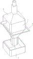
图1为一种气缸进气用过滤器组装结构立体图;Fig. 1 is a perspective view of the assembly structure of a filter for air intake of a cylinder;
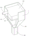
图2为输送箱体结构立体图;Fig. 2 is a three-dimensional view of the transport box structure;
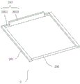
图3为连接架结构立体图;Fig. 3 is a three-dimensional view of the connecting frame structure;
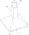
图4为集中斗结构立体图;Fig. 4 is a three-dimensional view of the concentrated bucket structure;
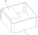
图5为底盒体结构立体图。Fig. 5 is a perspective view of the structure of the bottom box body.
附图标记:Reference signs:
1、输送箱体;101、活动口;102、支撑框;103、滤芯;104、输气管;105、输送斗;106、输入方管;2、连接架;201、连接条;202、连接杆;203、刮动结构;2031、连接块;2032、刮板;3、集中斗;301、密封垫;302、输送壳;303、输送管;4、底盒体;401、吸水海绵。1. Conveying box; 101, movable port; 102, support frame; 103, filter element; 104, air pipe; 105, conveying bucket; 106, input square pipe; 2, connecting frame; 201, connecting bar; 202, connecting
具体实施方式Detailed ways
下面将结合本实用新型实施例中的附图,对本实用新型实施例中的技术方案进行清楚、完整地描述。The following will clearly and completely describe the technical solutions in the embodiments of the present invention with reference to the drawings in the embodiments of the present invention.
请参阅图1-5所示,本实用新型为一种气缸进气用过滤器,包括输送箱体1、连接架2、集中斗3和底盒体4,输送箱体1的下方设置有底盒体4,输送箱体1内滤芯103滤出的灰尘通过底盒体4收集,底盒体4内设置有吸水海绵401,通过吸水海绵401在输入方管106出气的时候,先将其移动到输入方管106底部,再将一定水放到吸水海绵401上,让吸水海绵401吸收,将输入方管106中导出的空气中的灰尘等进行承接,防止灰尘逸散到空气中,输送箱体1的两侧位置对应地贯通开设有活动口101,输送箱体1通过活动口101在工作时,将连接架2活动连接在输送箱体1内,活动口101内活动连接有连接架2,连接架2包括活动连接在活动口101内的刮动结构203,连接架2在输送箱体1上运动的时候,通过刮动结构203将滤芯103底部滤出的灰尘等刮下来,输送箱体1的顶部固定有集中斗3,集中斗3用于集中输送滤芯103过滤后的空气。Please refer to Fig. 1-5, the utility model is a filter for air intake of a cylinder, which includes a
其中如图1、2所示,输送箱体1内壁的活动口101上方固定有支撑框102,支撑框102上方的输送箱体1内固定有滤芯103,输送箱体1在工作时,通过支撑框102提供输送箱体1的支撑,通过滤芯103将经过输送箱体1内的空气进行过滤。Wherein as shown in Figures 1 and 2, a
其中如图1、2所示,滤芯103一侧的输送箱体1上方固定连通有输气管104,输送箱体1的底部固定有输送斗105,输送斗105的底部固定连通有输入方管106,输气管104与输送高压空气的管路连通,通过输气管104将高压空气吹到输送箱体1内,使得滤芯103上产生高压,使得滤芯103中滤出的灰尘等,被吹动,导到输送斗105中,再通过输送斗105导到输入方管106中,通过输入方管106导到底盒体4中。Wherein, as shown in Figures 1 and 2, an
其中如图1、3所示,刮动结构203包括连接块2031和刮板2032,刮板2032活动连接在支撑框102内,且刮板2032的两端固定有连接块2031,连接块2031分别活动连接在输送箱体1两侧的活动口101内,刮动结构203通过连接块2031活动连接在活动口101内,通过刮板2032的运动,将滤芯103底部滤出的灰尘等刮下,落到输送斗105中。As shown in Figures 1 and 3, the
其中如图1、3所示,连接架2还包括连接条201和两个连接杆202,两个连接块2031远离刮板2032的一端皆固定连接有连接条201,两个连接条201互相靠近一面远离刮动结构203的一端共同固定有连接杆202,连接架2通过连接条201与连接块2031固定连接,使得在拉动连接杆202时,带动连接架2整体在输送箱体1中运动。Wherein, as shown in Figures 1 and 3, the
其中如图1、4所示,集中斗3的底部固定有密封垫301,密封垫301固定连接在输送箱体1内的上部,通过密封垫301增加集中斗3和输送箱体1之间的密封性,集中斗3的顶部固定连通有输送壳302,输送壳302的顶端固定连通有输送管303,集中斗3将滤芯103滤出到输送箱体1内上部的空气集中导到输送壳302中,通过输送管303与气缸工作气路连通,工作气路中的负压,使得输送壳302中过滤后的空气被抽到气缸工作气路中。Wherein as shown in Fig. 1, 4, the bottom of
本实用新型的具体工作原理为:工作时,通过输送管303与气缸工作气路连通,工作时,工作气路中产生负压,使得滤芯103上方的输送箱体1内的空气被抽出,在输送箱体1内滤芯103上部产生负压,使得空气从输送箱体1底部的输入方管106中导到输送斗105中,再导到输送箱体1内,通过滤芯103过滤后,导到集中斗3中,通过输送管303与气缸工作气路连通,工作气路中的负压,使得输送壳302中过滤后的空气被抽到气缸工作气路中,在停机后,滤芯103底部滤出的灰尘落到输送斗105中,通过输入方管106导到底盒体4中,在滤芯103工作一定时间后,通过输气管104将高压空气吹到输送箱体1内,使得滤芯103上产生高压,使得滤芯103中滤出的灰尘等,被吹动,导到输送斗105中,再通过输送斗105导到输入方管106中,通过输入方管106导到底盒体4中,通过吸水海绵401在输入方管106出气的时候,先将其移动到输入方管106底部,再将一定水放到吸水海绵401上,让吸水海绵401吸收,将输入方管106中导出的空气中的灰尘等进行承接,防止灰尘逸散到空气中,完成后,拉动连接杆202时,带动连接架2整体在输送箱体1中运动,通过刮板2032被带动运动,将滤芯103底部滤出的灰尘等刮下,落到输送斗105中,再通过输入方管106导到底盒体4中。The specific working principle of the utility model is: when working, the
以上仅为本实用新型的优选实施例,并不限制本实用新型,任何对前述各实施例所记载的技术方案进行修改,对其中部分技术特征进行等同替换,所作的任何修改、等同替换、改进,均属于在本实用新型的保护范围。The above are only preferred embodiments of the present utility model, and do not limit the present utility model. Any modification to the technical solutions recorded in the foregoing embodiments, equivalent replacement of some of the technical features, any modification, equivalent replacement, and improvement , all belong to the protection scope of the present utility model.
Claims (6)
Priority Applications (1)
| Application Number | Priority Date | Filing Date | Title |
|---|---|---|---|
| CN202320763715.7U CN219023697U (en) | 2023-04-10 | 2023-04-10 | Filter for air inlet of air cylinder |
Applications Claiming Priority (1)
| Application Number | Priority Date | Filing Date | Title |
|---|---|---|---|
| CN202320763715.7U CN219023697U (en) | 2023-04-10 | 2023-04-10 | Filter for air inlet of air cylinder |
Publications (1)
| Publication Number | Publication Date |
|---|---|
| CN219023697U true CN219023697U (en) | 2023-05-16 |
Family
ID=86278376
Family Applications (1)
| Application Number | Title | Priority Date | Filing Date |
|---|---|---|---|
| CN202320763715.7U Expired - Fee Related CN219023697U (en) | 2023-04-10 | 2023-04-10 | Filter for air inlet of air cylinder |
Country Status (1)
| Country | Link |
|---|---|
| CN (1) | CN219023697U (en) |
-
2023
- 2023-04-10 CN CN202320763715.7U patent/CN219023697U/en not_active Expired - Fee Related
Similar Documents
| Publication | Publication Date | Title |
|---|---|---|
| CN208356353U (en) | A kind of dust collecting mechanism of box deduster | |
| CN211328543U (en) | Self-cleaning cloth bag dust removal device for building material workshop | |
| CN117760217B (en) | Sintering furnace with exhaust structure | |
| CN208975370U (en) | A kind of industrial dedusting device | |
| CN115282698A (en) | Efficient energy-saving emission-reducing waste gas treatment device for power plant and use method thereof | |
| CN202700258U (en) | Offline bag-type dust collector | |
| CN212177134U (en) | Spraying dust-settling device for coal mining and tunneling in coal mine | |
| CN215585733U (en) | Mining environmental protection engineering is with dust remover convenient to clearance filter screen | |
| CN222033992U (en) | A bag type dust collector for industrial dust | |
| CN205619538U (en) | Automatic equipment that cleans of central air conditioning bag dust filter | |
| CN221557859U (en) | Filter cylinder dust removal equipment | |
| CN211384294U (en) | A high-efficiency filter cartridge dust collector | |
| CN219290880U (en) | Ash hopper of a bag filter | |
| CN211987597U (en) | Ash removal device of pulse dust collector for feed production | |
| CN215585815U (en) | Self-cleaning air filter | |
| CN215782192U (en) | Low-resistance bag-type dust collector | |
| CN115213438A (en) | Double-gas-path circulating purification device for laser powder bed melting additive manufacturing | |
| CN209885426U (en) | A high-efficiency bag filter | |
| CN223324251U (en) | A pneumatic ash conveying device for improving dust removal efficiency | |
| CN217699583U (en) | High-voltage pulse dust remover convenient to maintain | |
| CN216566317U (en) | Air box pulse bag type dust collector | |
| CN220405130U (en) | Air cleaner for PCB equipment | |
| CN221674558U (en) | A dust collecting component and jaw crusher thereof | |
| CN221155898U (en) | Dust removing device of screw air compressor | |
| CN219072385U (en) | High-efficient filtration sack cleaner |
Legal Events
| Date | Code | Title | Description |
|---|---|---|---|
| GR01 | Patent grant | ||
| GR01 | Patent grant | ||
| CF01 | Termination of patent right due to non-payment of annual fee | ||
| CF01 | Termination of patent right due to non-payment of annual fee |
Granted publication date: 20230516 |