CN219022043U - An intelligent device for measuring and recovering drainage fluid - Google Patents
An intelligent device for measuring and recovering drainage fluid Download PDFInfo
- Publication number
- CN219022043U CN219022043U CN202223026883.2U CN202223026883U CN219022043U CN 219022043 U CN219022043 U CN 219022043U CN 202223026883 U CN202223026883 U CN 202223026883U CN 219022043 U CN219022043 U CN 219022043U
- Authority
- CN
- China
- Prior art keywords
- drainage
- fluid
- drainage liquid
- flow sensor
- drainage fluid
- Prior art date
- Legal status (The legal status is an assumption and is not a legal conclusion. Google has not performed a legal analysis and makes no representation as to the accuracy of the status listed.)
- Active
Links
Images


Classifications
-
- Y—GENERAL TAGGING OF NEW TECHNOLOGICAL DEVELOPMENTS; GENERAL TAGGING OF CROSS-SECTIONAL TECHNOLOGIES SPANNING OVER SEVERAL SECTIONS OF THE IPC; TECHNICAL SUBJECTS COVERED BY FORMER USPC CROSS-REFERENCE ART COLLECTIONS [XRACs] AND DIGESTS
- Y02—TECHNOLOGIES OR APPLICATIONS FOR MITIGATION OR ADAPTATION AGAINST CLIMATE CHANGE
- Y02W—CLIMATE CHANGE MITIGATION TECHNOLOGIES RELATED TO WASTEWATER TREATMENT OR WASTE MANAGEMENT
- Y02W30/00—Technologies for solid waste management
- Y02W30/10—Waste collection, transportation, transfer or storage, e.g. segregated refuse collecting, electric or hybrid propulsion
Landscapes
- External Artificial Organs (AREA)
Abstract
本实用新型提供一种智能化引流液测量回收装置,推车上设置有桶座,桶座上安放有引流液收集桶,引流液收集桶的顶面设置有盖板,引流液收集桶的底部设置有排液阀,盖板上分别设置有排气口、引流液入口,排气口内设置有吸附剂;引流液入口通过体外引流管与一次性使用引流液袋的引流液出口连接,体外引流管上依次设置有流量传感器、电磁阀,其中流量传感器靠近的盖板一端,电磁阀、流量传感器分别与控制器电连接。本实用新型通过流量传感器对一次性使用引流液袋(或引流球)内的引流液进行自动定时计量后倾倒回收,不需要医护人员人工记录流量,降低了护理人员的劳动强度和感染风险,并能够及时将患者的引流液的状态进行记录,计量准确,使用方便。

The utility model provides an intelligent drainage fluid measurement and recovery device. A bucket seat is arranged on the trolley, a drainage fluid collection barrel is placed on the bucket seat, a cover plate is arranged on the top surface of the drainage fluid collection bucket, and a bottom of the drainage fluid collection bucket A drain valve is provided, and the cover plate is respectively provided with an exhaust port and a drainage liquid inlet, and an adsorbent is arranged in the exhaust port; the drainage liquid inlet is connected with the drainage liquid outlet of the disposable drainage liquid bag through the external drainage tube, and the external drainage A flow sensor and a solenoid valve are sequentially arranged on the tube, wherein the flow sensor is close to the end of the cover plate, and the solenoid valve and the flow sensor are respectively electrically connected to the controller. The utility model uses a flow sensor to automatically and regularly measure the drainage fluid in the drainage fluid bag (or drainage ball) for one-time use, and then dumps and recycles it. It does not require medical staff to manually record the flow rate, reduces the labor intensity and infection risk of the nursing staff, and The state of the patient's drainage fluid can be recorded in time, the measurement is accurate, and the use is convenient.
Description
技术领域technical field
本实用新型涉及医疗器具技术领域,具体涉及一种智能化引流液测量回收装置。The utility model relates to the technical field of medical appliances, in particular to an intelligent drainage fluid measurement and recovery device.
背景技术Background technique
外科手术后,有些患者会留置胃管、胸腹腔引流管、尿管等常见管道,通过引流达到减轻压力、缓解疼痛、减轻炎症、促进伤口愈合的目的。After surgery, some patients will indwell common tubes such as gastric tubes, thoracoabdominal drainage tubes, and urinary catheters to reduce pressure, relieve pain, reduce inflammation, and promote wound healing through drainage.
留置管道的一端设置在患者体内,另一端与体外的一次性使用引流液袋(或引流球)相连通,引流液通过引流液管将体内的引流液,引流到一次性使用引流液袋(或引流球)内。引流液袋内的引流液,必须定时的倾倒回收,并进行计量,通过观察患者的引流液的性、质、量,判断患者病情变化,准确记录引流量,是观察病情变化的重要依据。One end of the indwelling pipeline is set in the patient's body, and the other end is connected with the disposable drainage bag (or drainage ball) outside the body, and the drainage fluid in the body is drained to the disposable drainage bag (or drainage ball) through the drainage tube. drainage ball). The drainage fluid in the drainage fluid bag must be dumped and recovered regularly and measured. By observing the nature, quality, and quantity of the patient's drainage fluid, it is important to judge the patient's condition change and accurately record the drainage volume.
准确测量引流液液量是一项重要工作,经常需要精确至毫升。一次性使用引流液袋(或引流球)在实际的护理操作中发现其刻度标量存在误差,容易误导临床引流液计量,测量不准确,目前,常用的方法是医护人员采用人工操作的方法:1)、通过使用最小刻度为1ml的50m1注射器(透明白泵针),从一次性使用引流液袋(或引流球)底部的引流液出口将引流液袋内的引流液抽出、计量,然后倒于回收桶;2)、使用量杯,通过一次性使用引流液袋(或引流球)底部的引流液出口将引流液流入量杯计量后,然后倒于回收桶,而一次性使用引流液袋(或引流球)的容量通常为1000ml,存在以下技术缺陷:当一次性使用引流液袋(或引流球)内液体较多时,必须反复用50m1注射器抽吸测量或者使用多个量杯反复倾倒(每个量杯只能使用一次,然后就要浸泡消毒、清水清洗、并在晾干后才能重新投入使用),增加了护理人员的劳动强度,与体液频繁接触导致感染率高;使用空针抽吸引流液时易存在空气,排气过程中会排出引流液,导致计量不准确,误导医务人员对病情判断错误,给患者增加痛苦。Accurately measuring the volume of drainage fluid is an important task and often needs to be accurate to the milliliter. Disposable drainage bags (or drainage balls) are found to have errors in the scale and scale in actual nursing operations, which can easily mislead clinical drainage fluid measurement and inaccurate measurement. At present, the commonly used method is manual operation by medical staff: 1 ), using a 50m1 syringe (transparent white pump needle) with a minimum scale of 1ml, draw out and measure the drainage fluid in the drainage fluid bag (or drainage ball) from the drainage fluid outlet at the bottom of the disposable drainage fluid bag (or drainage ball), and then pour it into Recovery bucket; 2), use a measuring cup, measure the drainage fluid into the measuring cup through the drainage fluid outlet at the bottom of the disposable drainage fluid bag (or drainage ball), and then pour it into the recovery bucket, while the disposable drainage fluid bag (or drainage ball) The capacity of the ball) is usually 1000ml, and there are the following technical defects: when there is a lot of liquid in the disposable drainage bag (or drainage ball), it is necessary to use a 50m1 syringe repeatedly for suction measurement or use multiple measuring cups to pour repeatedly (each measuring cup only It can be used once, and then it must be soaked and disinfected, washed with clean water, and put into use after drying), which increases the labor intensity of the nursing staff, and frequent contact with body fluids leads to a high infection rate; In the presence of air, the drainage fluid will be discharged during the exhaust process, resulting in inaccurate measurement, misleading medical staff to wrongly judge the condition, and increasing pain to patients.
因此,如何设计一种智能化引流液测量回收装置,成为急需解决的问题。Therefore, how to design an intelligent drainage fluid measurement and recovery device has become an urgent problem to be solved.
实用新型内容Utility model content
针对现有技术存在的问题,本实用新型提供一种智能化引流液测量回收装置,以解决上述至少一种技术问题。Aiming at the problems existing in the prior art, the utility model provides an intelligent drainage fluid measurement and recovery device to solve at least one of the above technical problems.
本实用新型的技术方案是:一种智能化引流液测量回收装置,包括推车,所述推车上设置有桶座,桶座上安放有引流液收集桶,引流液收集桶的顶面设置有盖板,引流液收集桶的底部设置有排液阀,盖板上分别设置有排气口、引流液入口,排气口内设置有吸附剂;引流液入口通过体外引流管与一次性使用引流液袋(或引流球)的引流液出口连接,体外引流管上依次设置有流量传感器、电磁阀,流量传感器靠近的盖板一端,电磁阀、流量传感器分别与控制器电连接,控制器还与记录仪电连接,控制器接电源;控制器、记录仪、电磁阀、流量传感器均属于中江节能电子有限公司的S301定量表套装或上海硕舟电子科技有限公司的SZLDE-C插入式智能电磁流量计套装中的任意一种。The technical scheme of the utility model is: an intelligent drainage fluid measurement and recovery device, including a cart, the cart is provided with a bucket seat, a drainage fluid collection barrel is placed on the bucket seat, and the top surface of the drainage fluid collection barrel is arranged There is a cover plate, the bottom of the drainage liquid collection barrel is provided with a drain valve, and the cover plate is respectively provided with an exhaust port and a drainage liquid inlet, and an adsorbent is arranged in the exhaust port; the drainage liquid inlet is connected to the disposable drainage tube through the external drainage tube. The drainage fluid outlet of the fluid bag (or drainage ball) is connected, and the drainage tube in vitro is provided with a flow sensor and a solenoid valve in sequence. The recorder is electrically connected, and the controller is connected to the power supply; the controller, recorder, solenoid valve, and flow sensor all belong to the S301 quantitative meter set of Zhongjiang Energy Saving Electronics Co., Ltd. or the SZLDE-C plug-in intelligent electromagnetic flow rate of Shanghai Shuozhou Electronic Technology Co., Ltd. any of the meter sets.
本实用新型采用吸附剂,避免了从排气口排出的气体污染空气;通过流量传感器对一次性使用引流液袋(或引流球)内的引流液进行自动定时计量后倾倒回收,不需要医护人员人工记录流量,降低了护理人员的劳动强度,并能够及时将患者的引流液的状态进行记录,能及时告知医护及时处理,并大大降低了护理人员体液感染率,计量准确,使用方便,解决了使用空针抽吸引流液时易存在空气的技术缺陷,解决了量杯只能使用一次,然后就要清洗、消毒并在晾干后才能重新投入使用的技术缺陷,能够满足临床应用的需要。The utility model adopts the adsorbent, which avoids air pollution from the gas discharged from the exhaust port; the drainage liquid in the disposable drainage liquid bag (or drainage ball) is automatically and regularly measured by the flow sensor, and then dumped and recovered, without the need for medical personnel Manually recording the flow rate reduces the labor intensity of the nursing staff, and can record the status of the patient's drainage fluid in time, inform the medical staff and nurses to deal with it in time, and greatly reduce the body fluid infection rate of the nursing staff. The measurement is accurate and easy to use, which solves the problem of The technical defect that air is easy to exist when using an empty needle to aspirate fluid, solves the technical defect that the measuring cup can only be used once, and then it must be cleaned, sterilized and dried before being put into use again, which can meet the needs of clinical application.
附图说明Description of drawings
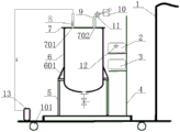
图1为本实用新型实施例一的安装结构示意图。Fig. 1 is a schematic diagram of the installation structure of the first embodiment of the utility model.
图2为本实用新型实施例二的安装结构示意图。Fig. 2 is a schematic diagram of the installation structure of the second embodiment of the utility model.
图3为本实用新型实施例六的安装结构示意图。Fig. 3 is a schematic diagram of the installation structure of
图中:1.推车;2.控制器;3.记录仪;4.机架;5.桶座;6.引流液收集桶;7.盖板;8.吸附剂;9.体外引流管;10.电磁阀;11.流量传感器;12.无线发射装置;13.真空装置;101.脚轮;601.支脚;701.排气口;702.引流液入口。In the figure: 1. Cart; 2. Controller; 3. Recorder; 4. Rack; 5. Bucket seat; 6. Drainage fluid collection bucket; 7. Cover plate; ; 10. Solenoid valve; 11. Flow sensor; 12. Wireless transmitting device; 13. Vacuum device; 101. Casters;
具体实施方式Detailed ways
下面结合附图对本实用新型做进一步的说明。Below in conjunction with accompanying drawing, the utility model is described further.
参阅图1-3,本说明书所附图式所绘示的结构、比例、大小等,均仅用以配合说明书所揭示的内容,以供熟悉此技术的人士了解与阅读,并非用以限定本实用新型可实施的限定条件,故不具技术上的实质意义,任何结构的修饰、比例关系的改变或大小的调整,在不影响本实用新型所能产生的功效及所能达成的目的下,仍均应落在本实用新型所揭示的技术内容能涵盖的范围内。同时,本说明书中所引用的如“上”、“下”、“左”、“右”、“中间”及“一”等的用语,亦仅为便于叙述的明了,而非用以限定本实用新型可实施的范围,其相对关系的改变或调整,在无实质变更技术内容下,当亦视为本实用新型可实施的范畴。Referring to Figures 1-3, the structures, proportions, sizes, etc. shown in the drawings attached to this manual are only used to match the content disclosed in the manual, for those who are familiar with this technology to understand and read, and are not intended to limit the scope of this manual. The limited conditions for the implementation of the utility model, so it has no technical substantive meaning, any modification of the structure, change of the proportional relationship or adjustment of the size, without affecting the effect and the purpose of the utility model, still All should fall within the scope covered by the technical content disclosed in the utility model. At the same time, terms such as "upper", "lower", "left", "right", "middle" and "one" quoted in this specification are only for the convenience of description and are not used to limit this specification. The practicable range of the utility model, and the change or adjustment of its relative relationship, without any substantial change in the technical content, shall also be regarded as the practicable scope of the utility model.
实施例一、一种智能化引流液测量回收装置,参考图1,包括带有推把的推车1,所述推车1上设置有桶座5,桶座5上安放有引流液收集桶6,引流液收集桶6的顶面设置有盖板7,引流液收集桶6的底部设置有排液阀,盖板7上分别设置有排气口701、引流液入口702,排气口701内设置有吸附剂8;引流液入口702通过体外引流管9与一次性使用引流液袋(或引流球)的引流液出口连接,体外引流管9上依次设置有流量传感器11、电磁阀10,其中流量传感器11靠近的盖板7一端,电磁阀10、流量传感器11分别与控制器2电连接,控制器2还与记录仪3电连接,控制器2接电源;控制器2、记录仪3、电磁阀10、流量传感器11均属于中江节能电子有限公司的S301定量表套装或上海硕舟电子科技有限公司的SZLDE-C插入式智能电磁流量计套装中的任意一种。本实用新型采用吸附剂,避免了从排气口排出的气体污染空气;通过流量传感器对一次性使用引流液袋(或引流球)内的引流液进行自动定时计量后倾倒回收,不需要医护人员人工记录流量,降低了护理人员的劳动强度,并能够及时将患者的引流液的状态进行记录,能及时告知医护及时处理,并大大降低了护理人员体液感染率,计量准确,使用方便,解决了使用空针抽吸引流液时易存在空气的技术缺陷,解决了量杯只能使用一次,然后就要清洗、消毒并在晾干后才能重新投入使用的技术缺陷,能够满足临床应用的需要。Embodiment 1. An intelligent drainage fluid measurement and recovery device, referring to FIG. 1 , includes a cart 1 with a push handle, the cart 1 is provided with a
实施例二、在实施例一的基础上,参考图2,所述桶座5安装在带有推把的推车1上,推车1上还设置有机架4,机架4上设置有沿着竖向间距布置的隔板,两块隔板上从上到下依次放置有控制器2、记录仪3;所述推车1的底面设置有四个脚轮101,四个脚轮101分布于长方形的四个角点,四个脚轮101采用带有刹车的万向脚轮。本实用新型采用在推车上设置有机架及机架上的隔板,用于放置控制器和记录仪;推车采用四个带有刹车的万向脚轮,便于推车的移动及使用。
实施例三、在实施例一的基础上,所述引流液收集桶6的底面为半球面结构,半球面结构的底面中心设置有排液管,排液阀安装在排液管上。本实用新型在引流液收集桶的底面采用半球面结构,便于引流液在引流液收集桶内收集后排出。
实施例四、在实施例三的基础上,所述桶座5为框架结构,框架结构的顶面设置有顶板,顶板的中心设置有第一通孔,第一通孔的外圈设置有数个绕圆周均布的第二通孔,引流液收集桶6的下部外圈设置有数个绕圆周均布的支脚601,支脚601上设置有第三通孔,第三通孔与第二通孔对应布置,第三通孔与第二通孔内共同设置有螺栓,螺栓通过螺母锁紧。本实用新型采用在框架结构的顶面设置第一通孔,在引流液收集桶的外圈设置数个支脚,将引流液收集桶放入第一通孔后,支脚底面放置在框架结构的顶面,通过螺栓、螺母将桶座与引流液收集桶连接,通过螺旋连接能方便的更换引流液收集桶。
实施例五、在实施例四的基础上,所述支脚601为L型结构,L型结构的竖板与引流液收集桶6的外圈连接,第三通孔设置于L型结构的横板上,L型结构的两侧面分别设置有三角形的封板。本实用新型采用L型结构的支脚,连接更加紧固。
实施例六、在实施例四的基础上,参考图3,所述排气口701通过气管与真空装置13连接,真空装置13接电源;真空装置13采用外购的无油隔膜真空泵,无油隔膜真空泵采用成都海霖科技有限公司的VBY8009A微型真空泵,最大可抽0.08MPa。本实用新型的排气口采用气管连接无油隔膜真空泵,引流液袋中的引流液不能顺畅流通时,可开启无油隔膜真空泵进行引流。
实施例七、在实施例六的基础上,所述控制器2上设有无线发射装置12,无线发射装置12采用上海硕舟电子科技有限公司的无线传输装置4G RTU ZHC4921。本实用新型采用无线发射装置,即可将流量信号发送到护士台,以便医护及时了解患者引流状态。
具体实施时,本实用新型的使用过程:当需要进行引流液测量回收时,将体外引流管9的另一端与一次性使用引流液袋(或引流球)的出口相连通,然后开启电源,控制器2给出信号,电磁阀10开启,一次性使用引流液袋(或引流球)中的引流液通过体外引流管9流入引流液收集桶6,流量传感器11将流量信号传送给控制器2,控制器2将流量信号传送给记录仪3记录;当流量为0时,控制器2给出信号,电磁阀10关闭;引流液收集桶6可清洗、可消毒、可重复使用。During specific implementation, the use process of the present utility model: when the drainage fluid needs to be measured and recovered, the other end of the
以上仅是本实用新型的优选实施方式,应当指出,对于本技术领域的普通技术人员来说,在不脱离本实用新型原理的前提下,还可以做出若干改进和润饰,这些改进和润饰也应视为本实用新型的保护范围。The above are only preferred embodiments of the present utility model, and it should be pointed out that for those of ordinary skill in the art, without departing from the principle of the present utility model, some improvements and modifications can also be made. It should be regarded as the protection scope of the present utility model.
Claims (7)
Priority Applications (1)
| Application Number | Priority Date | Filing Date | Title |
|---|---|---|---|
| CN202223026883.2U CN219022043U (en) | 2022-11-15 | 2022-11-15 | An intelligent device for measuring and recovering drainage fluid |
Applications Claiming Priority (1)
| Application Number | Priority Date | Filing Date | Title |
|---|---|---|---|
| CN202223026883.2U CN219022043U (en) | 2022-11-15 | 2022-11-15 | An intelligent device for measuring and recovering drainage fluid |
Publications (1)
| Publication Number | Publication Date |
|---|---|
| CN219022043U true CN219022043U (en) | 2023-05-16 |
Family
ID=86279539
Family Applications (1)
| Application Number | Title | Priority Date | Filing Date |
|---|---|---|---|
| CN202223026883.2U Active CN219022043U (en) | 2022-11-15 | 2022-11-15 | An intelligent device for measuring and recovering drainage fluid |
Country Status (1)
| Country | Link |
|---|---|
| CN (1) | CN219022043U (en) |
Cited By (1)
| Publication number | Priority date | Publication date | Assignee | Title |
|---|---|---|---|---|
| CN118374331A (en) * | 2024-04-17 | 2024-07-23 | 中国人民解放军海军军医大学第一附属医院 | Drainage fluid amylase uninterrupted detection device and detection method |
-
2022
- 2022-11-15 CN CN202223026883.2U patent/CN219022043U/en active Active
Cited By (2)
| Publication number | Priority date | Publication date | Assignee | Title |
|---|---|---|---|---|
| CN118374331A (en) * | 2024-04-17 | 2024-07-23 | 中国人民解放军海军军医大学第一附属医院 | Drainage fluid amylase uninterrupted detection device and detection method |
| CN118374331B (en) * | 2024-04-17 | 2025-10-10 | 中国人民解放军海军军医大学第一附属医院 | Drainage fluid amylase uninterrupted detection device and detection method |
Similar Documents
| Publication | Publication Date | Title |
|---|---|---|
| CN208525537U (en) | A kind of automatic enteroclysm device | |
| CN209734643U (en) | A urological flushing device | |
| CN101711679A (en) | Quick urine drainage and determination system | |
| CN206434630U (en) | A kind of liver and gall surgical department's drainage system | |
| CN211357073U (en) | Continuous bladder irrigation closed drainage liquid collecting device | |
| CN219804036U (en) | Sputum aspirator with automated inspection sputum volume | |
| CN209864824U (en) | A bladder irrigation and drainage device | |
| CN209204222U (en) | Thorax closed drainage device of real-time detection waste liquid flow | |
| CN207270517U (en) | A kind of disposable bladder irrigation and drainage bottle | |
| CN209122685U (en) | A detection and nursing device for urology that is easy to add medicine | |
| CN201894761U (en) | Bladder washing fluid collecting device with filter | |
| CN116688277A (en) | An intelligent surgical irrigation and drainage device | |
| CN217886053U (en) | Urinary catheterization device capable of automatically retaining midstream urine | |
| CN211068297U (en) | Urinary surgery is with catheterization device | |
| CN211096467U (en) | Urinary surgery is catheter device for clinic | |
| CN209032443U (en) | Middle section urine sampler | |
| CN215023592U (en) | Bladder washing unit for uropoiesis surgery | |
| CN209173024U (en) | A kind of pancreatic juice drainage bag of delicate metering | |
| CN223473740U (en) | Intra-abdominal pressure detection device | |
| CN213667363U (en) | Breathing machine pipeline condensate water processing apparatus | |
| CN221866868U (en) | Composite functional bladder irrigator | |
| CN221451307U (en) | An integrated negative pressure drainage device | |
| CN216824330U (en) | Bladder blood clot negative pressure washes drainage integrative device | |
| CN224112701U (en) | Urine collection bag with urine collection function | |
| CN206183770U (en) | Automatic collection device of breathing machine comdenstion water |
Legal Events
| Date | Code | Title | Description |
|---|---|---|---|
| GR01 | Patent grant | ||
| GR01 | Patent grant |