CN219003368U - High-efficiency energy-saving splash-proof easy-cleaning type tailing recycling machine - Google Patents
High-efficiency energy-saving splash-proof easy-cleaning type tailing recycling machine Download PDFInfo
- Publication number
- CN219003368U CN219003368U CN202223408929.7U CN202223408929U CN219003368U CN 219003368 U CN219003368 U CN 219003368U CN 202223408929 U CN202223408929 U CN 202223408929U CN 219003368 U CN219003368 U CN 219003368U
- Authority
- CN
- China
- Prior art keywords
- water
- discs
- disc
- protective cover
- frame
- Prior art date
- Legal status (The legal status is an assumption and is not a legal conclusion. Google has not performed a legal analysis and makes no representation as to the accuracy of the status listed.)
- Active
Links
Images


Landscapes
- Water Treatment By Electricity Or Magnetism (AREA)
Abstract
本实用新型属于尾矿回收技术领域,尤其是涉及一种高效节能防喷溅易清洁型尾矿回收机,其特征在于包括机架,转动轴,尾矿斗,沿转动轴的轴向间隔排布的若干个圆盘,分别设置于相邻两个圆盘之间的若干个溜槽,位于圆盘上方的喷水组件,圆盘的前上方的防护罩,防护罩内壁上的喷气件,每个圆盘内部均设有磁盘,磁块。本实用新型利用装有磁盘的圆盘吸附尾矿斗内的磁矿,喷水组件对圆盘的侧壁进行喷淋使磁矿落至溜槽内,防护罩避免了喷淋水向外部喷溅,喷气件向相邻两个圆盘的间隙内喷气,既可以利用气流卸落圆盘上的磁矿,又可以避免水花的飞溅,喷水组件可通过旋转驱动件进行旋转驱动,以使喷水组件向前旋转摆动以远离圆盘,便于进行清理或更换。
The utility model belongs to the technical field of tailings recycling, in particular to a high-efficiency, energy-saving, splash-proof and easy-to-clean tailings recycling machine, which is characterized in that it includes a frame, a rotating shaft, a tailings bucket, and an axially spaced row along the rotating shaft. Several discs of the cloth are respectively arranged in several chutes between adjacent two discs, the water spray assembly above the discs, the protective cover above the front of the disc, and the air jet on the inner wall of the protective cover. Disks and magnetic blocks are arranged inside each disc. The utility model utilizes a disc equipped with a magnetic disk to absorb the magnetic ore in the tailings hopper, and the water spray assembly sprays the side wall of the disc to make the magnetic ore fall into the chute, and the protective cover prevents the spray water from splashing to the outside , the air spraying part sprays air into the gap between two adjacent discs, which can not only use the air flow to unload the magnetic ore on the discs, but also avoid splashing of water splashes. The water assembly swivels forward and away from the disc for easy cleaning or replacement.
Description
技术领域technical field
本实用新型属于尾矿回收技术领域,尤其是涉及一种高效节能防喷溅易清洁型尾矿回收机。The utility model belongs to the technical field of tailings recycling, in particular to a high-efficiency, energy-saving, splash-proof and easy-to-clean tailings recycling machine.
背景技术Background technique
在对磁矿进行分选后会将剩余的尾矿抛掉,为了提高资源利用率、避免造成资源浪费,在分选后后增加尾矿回收机对尾矿中的磁矿进行回收。但是,现有的尾矿回收机利用磁盘对磁矿进行磁吸,吸附的磁性物需要刮板刮除,常常存在卸落不彻底的问题。虽然有的尾矿回收机上采用了喷水管对圆盘侧壁进行喷水以卸落磁矿的方式,但是容易产生溅水的问题,影响磁矿的卸落效果,难以将圆盘上的磁矿喷落达到有效的收集效果,另外,喷水管使用中容易堵塞,清理起来十分不便。After sorting the magnetic ore, the remaining tailings will be thrown away. In order to improve resource utilization and avoid resource waste, a tailings recycling machine is added after sorting to recover the magnetic ore in the tailings. However, the existing tailings recycling machine uses a magnetic disk to magnetically attract the magnetic ore, and the adsorbed magnetic material needs to be scraped off by a scraper, which often has the problem of incomplete removal. Although some tailings recovery machines use a water spray pipe to spray water on the side wall of the disc to remove the magnetite, but it is easy to cause the problem of splashing water, which affects the effect of the magnetite removal, and it is difficult to remove the magnetite on the disc. The magnetic ore is sprayed down to achieve an effective collection effect. In addition, the water spray pipe is easily blocked during use, and it is very inconvenient to clean.
申请号为CN202110287490.8的一种尾矿回收机,当水流沿着刮板流通至收集池中时,水流会对承接板造成冲击,从而能够克服弹簧的弹力并带动滑动块沿着滑动槽进行移动,移动的过程中抵接杆能够带动棘轮进行转动,棘轮转动时能够带动绞龙芯进行转动,从而能够对收集池中的铁粉进行清理。但是,喷淋水喷溅严重,影响磁矿的卸落效果。申请号为CN201320653177.2的新型尾矿回收机,也设置稀释喷淋管和脱料喷淋管以稀释矿浆浓度和帮助脱料,提高工作效率。但是依然存在喷淋水喷溅严重,难以将磁矿有效收集的问题。A tailings recycling machine with application number CN202110287490.8, when the water flows along the scraper to the collection pool, the water will impact the receiving plate, which can overcome the elastic force of the spring and drive the sliding block to move along the sliding groove. Move, the abutment rod can drive the ratchet to rotate during the movement, and the ratchet can drive the twisted dragon core to rotate when the ratchet rotates, so that the iron powder in the collection pool can be cleaned. However, the spraying water is seriously splashed, which affects the dropping effect of the magnetic ore. The new tailings recovery machine with the application number CN201320653177.2 is also provided with a dilution spray pipe and a stripping spray pipe to dilute the slurry concentration and help stripping, so as to improve work efficiency. But still there is the serious splash of spray water, it is difficult to effectively collect the problem of magnetite.
发明内容Contents of the invention
本实用新型的目的是提供一种高效节能防喷溅易清洁型尾矿回收机,通过可以改变角度的喷水组件实现对圆盘侧壁的磁矿进行有效卸落,提高磁矿的收集效率。The purpose of this utility model is to provide a high-efficiency, energy-saving, splash-proof and easy-to-clean tailings recovery machine, which can effectively unload the magnetic ore on the side wall of the disc through the water spray assembly that can change the angle, and improve the collection efficiency of the magnetic ore .
本实用新型的目的是通过下述技术方案来实现的:The purpose of this utility model is achieved through the following technical solutions:
本实用新型的高效节能防喷溅易清洁型尾矿回收机,其特征在于包括机架,与此机架转动连接且水平延伸的转动轴,设置在所述机架底部的尾矿斗,沿所述转动轴的轴向间隔排布的若干个圆盘,分别设置于相邻两个所述圆盘之间的若干个溜槽,转动连接于所述机架上、且位于所述圆盘上方的喷水组件,设于所述圆盘的前上方、且与所述机架相连的防护罩,设置在所述防护罩内壁上的喷气件,The high-efficiency, energy-saving, splash-proof and easy-to-clean tailings recovery machine of the utility model is characterized in that it comprises a frame, a rotating shaft that is rotatably connected with the frame and extends horizontally, and a tailings bucket arranged at the bottom of the frame, along which A plurality of discs arranged at intervals in the axial direction of the rotating shaft are respectively arranged in a plurality of chutes between two adjacent discs, are rotatably connected to the frame, and are located above the discs The water spraying assembly is arranged on the upper front of the disc and is connected to the protective cover of the frame, and the air injection part is arranged on the inner wall of the protective cover,
每个圆盘内部均设有磁盘,此磁盘上嵌装有磁块,所述的磁盘通过转动轴承转动连接于所述转动轴上。Each disc is provided with a magnetic disk inside, and a magnetic block is embedded on the magnetic disk, and the magnetic disk is rotatably connected to the rotating shaft through a rotating bearing.
所述的磁块在所述磁盘的端面上呈扇形排布、且靠近所述磁盘的中下部。The magnetic blocks are arranged in a fan shape on the end surface of the magnetic disk and are close to the middle and lower part of the magnetic disk.
所述的喷水组件包括转动连接于所述机架上的总水管,连接于此总水管下方的若干个支管,分别设置在所述支管两侧且朝向所述圆盘侧壁的出水管,所述的若干个支管向相邻两个所述圆盘的间隙内延伸、且与所述溜槽一一对应设置,The water spray assembly includes a main water pipe rotatably connected to the frame, several branch pipes connected under the water main pipe, water outlet pipes respectively arranged on both sides of the branch pipe and facing the side wall of the disc, The plurality of branch pipes extend into the gap between two adjacent discs and are arranged in one-to-one correspondence with the chute,
所述的总水管一端与供水水源通过旋转接头相连,另一端与旋转驱动件相连接。One end of the main water pipe is connected to the water supply source through a rotary joint, and the other end is connected to the rotary driving member.
所述的出水管靠近所述圆盘的上部设置、且所述出水管的出水方向与所述圆盘的侧壁之间具有锐角夹角。The water outlet pipe is arranged close to the upper part of the disk, and the water outlet direction of the water outlet pipe has an acute angle with the side wall of the disk.
所述的支管的端部连接有封堵帽,所述封堵帽与所述支管之间螺纹连接。The end of the branch pipe is connected with a sealing cap, and the sealing cap is threadedly connected with the branch pipe.
所述的总水管上连接有除杂管,所述除杂管位于所述总水管远离所述供水水源的一端的下方,所述总水管的进水端连接有水质净化器和增压泵。An impurity removal pipe is connected to the main water pipe, and the impurity removal pipe is located below the end of the water main pipe away from the water supply source, and a water purifier and a booster pump are connected to the water inlet end of the water main pipe.
所述的若干个圆盘中,相邻两个圆盘之间设有套设于所述转动轴上的导流套,所述导流套的外周壁上设有弧形槽,所述溜槽的上端沿所述导流套的切向延伸、且与所述导流套之间具有间隙。Among the several disks, a diversion sleeve set on the rotating shaft is arranged between two adjacent disks, and an arc-shaped groove is arranged on the outer peripheral wall of the diversion sleeve, and the chute The upper end of the upper end extends along the tangential direction of the diversion sleeve and has a gap with the diversion sleeve.
所述的相邻两个所述圆盘之间还设有挡水槽,所述挡水槽的下端与所述溜槽的上端相连,所述挡水槽的上端向后上方延伸。A water retaining groove is also provided between the two adjacent discs, the lower end of the water retaining groove is connected to the upper end of the chute, and the upper end of the water retaining groove extends rearward and upward.
所述的防护罩通过水平延伸的摆动轴转动连接于所述机架的前侧上方,所述防护罩与所述摆动轴之间通过顶丝固定,所述机架上还设有用于限定所述防护罩摆动幅度的限位挡块。The protective cover is rotatably connected to the upper front side of the frame through a horizontally extending swing shaft, and the protective cover and the swing shaft are fixed by jacking screws. The limit stopper for the swing range of the protective cover.
本实用新型的优点:Advantage of the utility model:
本实用新型的高效节能防喷溅易清洁型尾矿回收机,与现有技术相比,利用内部装有磁盘的圆盘吸附尾矿斗内的磁矿,设置在机架上的喷水组件对圆盘的侧壁进行喷淋使磁矿落至溜槽内,防护罩的设置避免了喷淋水向外部喷溅,防护罩内部的喷气件向相邻两个圆盘的间隙内喷气,既可以利用气流卸落圆盘上的磁矿,又可以避免水花的飞溅,喷水组件可通过旋转驱动件进行旋转驱动,以使喷水组件向前旋转摆动以远离圆盘,便于进行清理或更换。Compared with the prior art, the high-efficiency, energy-saving, splash-proof and easy-to-clean tailing recovery machine of the present utility model utilizes a disk equipped with a disk inside to absorb the magnetic ore in the tailings hopper, and the water spray assembly arranged on the frame The side wall of the disc is sprayed to make the magnetite fall into the chute, the setting of the protective cover prevents the spray water from splashing to the outside, and the air jet inside the protective cover sprays air into the gap between two adjacent discs, both The magnetic ore on the disc can be unloaded by air flow, and the splash of water can be avoided. The water spray assembly can be rotated and driven by the rotating drive, so that the water spray assembly can rotate forward and swing away from the disc, which is convenient for cleaning or replacement .
附图说明Description of drawings
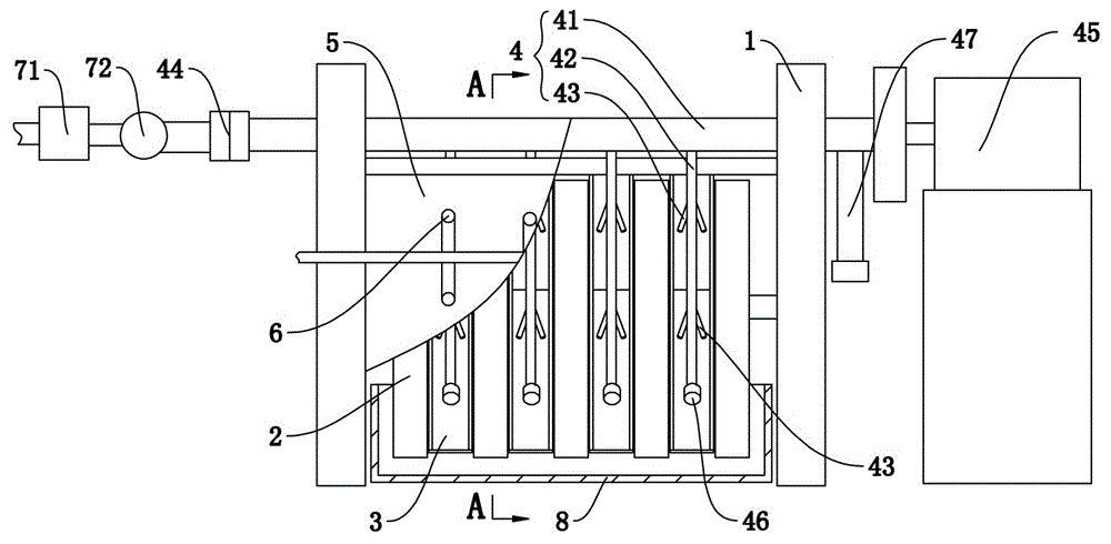
图1为本实用新型的主视局部剖视结构示意图。Fig. 1 is a schematic diagram of a partial cross-sectional structure of a front view of the utility model.
图2为本实用新型图1中A-A的剖视结构示意图。Fig. 2 is a schematic cross-sectional structure diagram of A-A in Fig. 1 of the present utility model.
图3为本实用新型图2中Ⅰ的局部放大结构示意图。Fig. 3 is a partial enlarged structural schematic diagram of I in Fig. 2 of the present utility model.
图4为本实用新型图1中圆盘、转动轴及导流套的主视结构示意图。Fig. 4 is a front structural diagram of the disk, the rotating shaft and the guide sleeve in Fig. 1 of the present utility model.
图5为本实用新型图1中圆盘和转动轴的左视剖视结构示意图。Fig. 5 is a left view sectional structural schematic diagram of the disc and the rotating shaft in Fig. 1 of the present invention.
具体实施方式Detailed ways
下面结合附图进一步说明本实用新型的具体实施方式。Further illustrate the specific embodiment of the present utility model below in conjunction with accompanying drawing.
如图1-5所示,本实用新型的高效节能防喷溅易清洁型尾矿回收机,其特征在于包括机架1,与此机架1转动连接且水平延伸的转动轴11,设置在所述机架1底部的尾矿斗8,沿所述转动轴11的轴向间隔排布的若干个圆盘2,分别设置于相邻两个所述圆盘2之间的若干个溜槽3,转动连接于所述机架1上、且位于所述圆盘2上方的喷水组件4,设于所述圆盘2的前上方、且与所述机架1相连的防护罩5,设置在所述防护罩5内壁上的喷气件6,As shown in Figures 1-5, the high-efficiency, energy-saving, splash-proof and easy-to-clean tailings recovery machine of the present utility model is characterized in that it includes a
每个圆盘2内部均设有磁盘21,此磁盘21上嵌装有磁块22,所述的磁盘21通过转动轴承12转动连接于所述转动轴11上。Each
所述的磁块22在所述磁盘21的端面上呈扇形排布、且靠近所述磁盘21的中下部。The
所述的喷水组件4包括转动连接于所述机架1上的总水管41,连接于此总水管41下方的若干个支管42,分别设置在所述支管2两侧且朝向所述圆盘2侧壁的出水管43,所述的若干个支管42向相邻两个所述圆盘2的间隙内延伸、且与所述溜槽3一一对应设置,The water spray assembly 4 includes a
所述的总水管41一端与供水水源通过旋转接头44相连,另一端与旋转驱动件45相连接。One end of the
所述的出水管43靠近所述圆盘2的上部设置、且所述出水管43的出水方向与所述圆盘2的侧壁之间具有锐角夹角。The
所述的支管42的端部连接有封堵帽46,所述封堵帽46与所述支管42之间螺纹连接。The end of the
所述的总水管41上连接有除杂管47,所述除杂管47位于所述总水管41远离所述供水水源的一端的下方,所述总水管41的进水端连接有水质净化器71和增压泵72。The
所述的若干个圆盘2中,相邻两个圆盘2之间设有套设于所述转动轴11上的导流套31,所述导流套31的外周壁上设有弧形槽,所述溜槽3的上端沿所述导流套31的切向延伸、且与所述导流套31之间具有间隙。Among the
所述的相邻两个所述圆盘2之间还设有挡水槽32,所述挡水槽32的下端与所述溜槽3的上端相连,所述挡水槽32的上端向后上方延伸。A
所述的防护罩5通过水平延伸的摆动轴转动连接于所述机架1的前侧上方,所述防护罩5与所述摆动轴之间通过顶丝81固定,所述机架1上还设有用于限定所述防护罩5摆动幅度的限位挡块82。The
为了使本实用新型所要解决的技术问题、技术方案及有益效果更加清楚明白,以下结合附图及实施例,对本实用新型进行进一步详细说明。应当理解,此处所描述的具体实施例仅仅用以解释本实用新型,并不用于限定本实用新型。In order to make the technical problems, technical solutions and beneficial effects to be solved by the utility model clearer, the utility model will be further described in detail below in conjunction with the accompanying drawings and embodiments. It should be understood that the specific embodiments described here are only used to explain the utility model, and are not intended to limit the utility model.
需要说明的是,当元件被称为“设置于”另一个元件,它可以直接在另一个元件上或者间接在另一个元件上。需要理解的是,术语“长度”、“宽度”、“上”、“下”、“前”、“后”、“顶”、“底”、“内”、“外”等指示的方位或位置关系为基于附图所示的方位或位置关系,仅是为了便于描述本实用新型和简化描述,而不是指示或暗示所指的装置或元件必须具有特定的方位、以特定的方位构造和操作,因此不能理解为对本实用新型的限制。术语“第一”、“第二”仅用于描述目的,而不能理解为指示或暗示相对重要性或者隐含指明所指示的技术特征的数量。由此,限定有“第一”、“第二”的特征可以明示或者隐含地包括一个或者若干个该特征。在本实用新型的描述中,“若干个”的含义是两个或两个以上,除非另有明确具体的限定。It should be noted that when an element is referred to as being “disposed on” another element, it may be directly on the other element or indirectly on the other element. It is to be understood that the terms "length", "width", "upper", "lower", "front", "rear", "top", "bottom", "inner", "outer" etc. indicate an orientation or The positional relationship is based on the orientation or positional relationship shown in the drawings, which is only for the convenience of describing the utility model and simplifying the description, and does not indicate or imply that the referred device or element must have a specific orientation, be constructed and operated in a specific orientation , so it cannot be interpreted as a limitation of the present utility model. The terms "first" and "second" are used for descriptive purposes only, and cannot be understood as indicating or implying relative importance or implicitly specifying the quantity of indicated technical features. Therefore, the features defined as "first" and "second" may explicitly or implicitly include one or several of these features. In the description of the present utility model, "several" means two or more, unless otherwise specifically defined.
需要说明的是,本实施例中,请参见图2,圆盘2的前侧指的是圆盘2靠近溜槽3的一侧,后侧指的是圆盘2远离溜槽3的一侧。It should be noted that, in this embodiment, please refer to FIG. 2 , the front side of the
请一并参阅图1至图5,现对本实用新型提供的高效节能防喷溅易清洁型尾矿回收机进行说明。高效节能防喷溅易清洁型尾矿回收机,包括机架1、若干个圆盘2、若干个溜槽3、喷水组件4、防护罩5以及喷气件6,机架1转动连接有水平延伸的转动轴11,机架1的底部设有尾矿斗8;圆盘2沿转动轴11的轴向间隔排布于转动轴11上,用于在转动轴11的带动下旋转,每个圆盘2内部均设有磁盘21,磁盘21上嵌装有磁块22、且磁盘21转动连接于转动轴11上;溜槽3设置于相邻两个圆盘2之间,用于承接圆盘2侧壁上卸落的磁矿;喷水组件4转动连接于机架1上、且位于圆盘2的上方,用于向圆盘2的侧壁上喷淋以卸落磁矿;防护罩5罩设于圆盘2的前上方,且与机架1相连;喷气件6设置于防护罩5的内壁上,用于向相邻两个圆盘2的间隙内喷气以卸落磁矿。Please refer to Fig. 1 to Fig. 5 together, and now the high-efficiency, energy-saving, splash-proof and easy-to-clean tailings recovery machine provided by the utility model will be described. High-efficiency, energy-saving, anti-splash and easy-to-clean tailings recycling machine, including
本实施例提供的高效节能防喷溅易清洁型尾矿回收机,与现有技术相比,本实施例提供的高效节能防喷溅易清洁型尾矿回收机,利用内部装有磁盘21的圆盘2吸附尾矿斗8内的磁矿,设置在机架1上的喷水组件4对圆盘2的侧壁进行喷淋使磁矿落至溜槽3内,防护罩5的设置避免了喷淋水向外部喷溅,防护罩5内部的喷气件6向相邻两个圆盘2的间隙内喷气,既可以利用气流卸落圆盘2上的磁矿,又可以避免水花的飞溅,喷水组件4可通过旋转驱动件45进行旋转驱动,以使喷水组件4向前旋转摆动以远离圆盘2,便于进行清理或更换。Compared with the prior art, the high-efficiency, energy-saving, splash-proof and easy-to-clean tailings recovery machine provided in this embodiment uses a
一些可能的实现方式中,上述特征磁盘21采用如图5所示结构。参见图5,转动轴11上套设有位于转动轴11与磁盘21之间的转动轴承12,磁块22在磁盘21的端面上呈扇形排布、且靠近磁盘21的中下部设置。In some possible implementation manners, the characteristic
转动轴承12使磁盘21与转动轴11之间顺畅的相对转动,使磁盘21不随转动轴11的转动旋转,便于减小溜槽3部位磁矿与圆盘2之间的磁吸力,便于卸落圆盘2上吸附的磁矿。The rotating
本实施例中,仅在磁盘21靠近中部和下部的位置设置磁块22,实现对尾矿中磁矿的有效吸附,在磁盘21上靠近上部的区域并不设置磁块22,减小该位置圆盘2对磁矿的吸附力,便于磁矿在喷水组件4的喷淋作用以及喷气件6的喷吹作用下进行卸落。In this embodiment, the
具体的,磁块22仅在磁盘21的中下部进行设置,在周向上成扇形布设,在圆盘2的周向上覆盖220°-300°之间的区域,剩余区域并不设置磁块22,在重力作用下,剩余未布设磁块22的区域靠近圆盘2的上部,与喷水组件4和喷气件6的作用区域相对应,使圆盘2与溜槽3对应的区域的磁吸力变小,有助于磁矿的充分卸落,减小喷水组件4所需的水压和喷气件6所需的风压,便于节约能源消耗。Specifically, the
溜槽3的前端向前延伸至与外部收集设备相连,另外,所有溜槽3的下端还可以连接在同一个出料槽上实现磁矿的排出。The front end of the
一些可能的实现方式中,上述特征喷水组件4采用如图1和图2所示结构。参见图1和图2,喷水组件4包括总水管41以及若干个支管42,总水管41转动连接于机架1上,且与供水水源通过旋转接头44相连,总水管41远离供水水源的一端连接有用于驱动总水管41旋转的旋转驱动件45;支管42连接于总水管41下方,且向相邻两个圆盘2的间隙内延伸、并与溜槽3一一对应设置,每个支管42的两侧分别设有朝向圆盘2的侧壁延伸的出水管43。In some possible implementations, the above-mentioned characteristic water spray assembly 4 adopts the structures shown in Fig. 1 and Fig. 2 . Referring to Fig. 1 and Fig. 2, the water spray assembly 4 includes a
利用旋转接头44将总水管41与供水水源相连,支管42连接在总水管41的下方,通过两侧设置的出水管43分别向两侧的圆盘2的侧壁上喷淋,使圆盘2侧面上磁矿有效卸落。旋转驱动件45可驱动总水管41旋转一定角度使支管42摆动至圆盘2的前侧、从圆盘2的间隙中移出后进行维修或清理,旋转接头44可以实现总水管41与供水水源之间的相对旋转。The
一些可能的实现方式中,上述特征出水管43采用如图1所示结构。参见图1,出水管43靠近圆盘2的上部设置,且出水管43的出水方向与圆盘2的侧壁之间具有锐角夹角。支管42的端部可拆卸连接有封堵帽46,封堵帽46与支管42之间螺纹连接。In some possible implementation manners, the above-mentioned characteristic
出水管43靠近圆盘2的上部设置,该区域为磁盘21未设置磁块22的区域,此时,圆盘2上的磁矿所受的吸附力最小,便于磁矿的卸落。出水管43的出水方向与圆盘2的侧壁之间形成锐角,该设置可在实现冲刷效果的同时减少喷溅。
当需要清理或者更换时,先关闭供水水源上的阀门,利用旋转驱动件45带动总水管41旋转,使连接在总水管41下方的支管42能够从两个圆盘2的间隙中脱出。拆卸掉支管42端部的封堵帽46,使支管42内的杂质有序排出。一些可能的实现方式中,上述特征总水管41采用如图1所示结构。参见图1,总水管41上连接有除杂管47,除杂管47位于总水管41远离供水水源的一端的下方。When cleaning or replacement is needed, first close the valve on the water supply source, and utilize the
请参阅图1,在对支管42进行清理除杂的基础上,还在总水管41上连接有除杂管47,除杂管47位于总水管41远离供水水源的一端,也就是靠近设有旋转驱动件45的一端,除杂管47向下延伸,其下端连接有堵头,可拆除堵头后可对总水管41内的杂质进行有效地清除,保证整个喷水组件4的内部清洁,进而保证喷水组件4对圆盘2上磁矿的喷淋作用。Please refer to Fig. 1, on the basis of cleaning the
进一步的,为了保证总水管41内水质的纯净度,在总水管41的进口进水端设置有水质净化器71,利用水质净化器71内部的滤芯对水中的杂质进行初步滤除,另外,为了保证喷水组件4对圆盘2进行喷淋时的水压,还设置了增压泵72以提高供水压力,提高磁矿的卸落效率。Further, in order to ensure the purity of the water quality in the
一些可能的实现方式中,参见图4,相邻两个圆盘2之间设有套设于转动轴11上的导流套31,导流套31的的外周壁上设有弧形槽,溜槽3的上端沿导流套31的切向延伸、且与导流套31之间具有间隙。In some possible implementations, referring to FIG. 4 , a
在两个圆盘2之间设置有导流套31,导流套31可以对两个圆盘2之间的间距进行限定,使二者之间的间隙能够有效容纳溜槽3,避免圆盘2与溜槽3之间产生位置干涉。另外,导流套31外周壁上设置的弧形槽可以使落在导流套31上的水分被即使导流至下方,避免水在导流套31的表面聚集。A
进一步的,参见图2,在相邻两个圆盘2之间设置有挡水槽32,挡水槽32的下端与溜槽3的上端相连,上端向远离溜槽3的后侧上方延伸,可以对水流进行阻挡,以便将水导送至溜槽3中。Further, referring to Fig. 2, a
一些可能的实现方式中,上述特征防护罩5采用如图2所示结构。参见图2,防护罩5通过水平延伸的摆动轴转动连接于机架1的前侧上方,防护罩5与摆动轴之间通过顶丝81固定,机架1上还设有用于限位防护罩5摆动幅度的限位挡块82。In some possible implementation manners, the above-mentioned
防护罩5通过摆动轴与机架1之间转动连接,检修时通过打开防护罩5进行喷水组件4的清理或更换。日常使用时,盖上防护罩5防止水流向外喷溅。防护罩5的上缘设有套在摆动轴上的轴套,轴套与摆动轴之间设有顶丝81,利用顶丝81固定防护罩5的位置,避免防护罩5在重力作用下摆动至与圆盘2接触。The
进一步的,在机架1上还设置有限位挡块82,限位挡块82可对防护罩5的侧壁进行位置限定,使防护罩5可以稳定地罩在圆盘2的前上方,实现良好的防护作用。Further, a
以上仅为本实用新型的较佳实施例而已,并不用以限制本实用新型,凡在本实用新型的精神和原则之内所作的任何修改、等同替换和改进等,均应包含在本实用新型的保护范围之内。The above are only preferred embodiments of the present utility model, and are not intended to limit the present utility model. Any modifications, equivalent replacements and improvements made within the spirit and principles of the present utility model should be included in the utility model. within the scope of protection.
本实用新型的高效节能防喷溅易清洁型尾矿回收机,与现有技术相比,利用内部装有磁盘21的圆盘2吸附尾矿斗内的磁矿,设置在机架1上的喷水组件4对圆盘2的侧壁进行喷淋使磁矿落至溜槽3内,防护罩5的设置避免了喷淋水向外部喷溅,防护罩5内部的喷气件6向相邻两个圆盘2的间隙内喷气,既可以利用气流卸落圆盘2上的磁矿,又可以避免水花的飞溅,喷水组件4可通过旋转驱动件45进行旋转驱动,以使喷水组件4向前旋转摆动以远离圆盘2,便于进行清理或更换。Compared with the prior art, the high-efficiency, energy-saving, splash-proof and easy-to-clean tailing recovery machine of the present utility model utilizes the
Claims (9)
Priority Applications (1)
| Application Number | Priority Date | Filing Date | Title |
|---|---|---|---|
| CN202223408929.7U CN219003368U (en) | 2022-12-20 | 2022-12-20 | High-efficiency energy-saving splash-proof easy-cleaning type tailing recycling machine |
Applications Claiming Priority (1)
| Application Number | Priority Date | Filing Date | Title |
|---|---|---|---|
| CN202223408929.7U CN219003368U (en) | 2022-12-20 | 2022-12-20 | High-efficiency energy-saving splash-proof easy-cleaning type tailing recycling machine |
Publications (1)
| Publication Number | Publication Date |
|---|---|
| CN219003368U true CN219003368U (en) | 2023-05-12 |
Family
ID=86269181
Family Applications (1)
| Application Number | Title | Priority Date | Filing Date |
|---|---|---|---|
| CN202223408929.7U Active CN219003368U (en) | 2022-12-20 | 2022-12-20 | High-efficiency energy-saving splash-proof easy-cleaning type tailing recycling machine |
Country Status (1)
| Country | Link |
|---|---|
| CN (1) | CN219003368U (en) |
-
2022
- 2022-12-20 CN CN202223408929.7U patent/CN219003368U/en active Active
Similar Documents
| Publication | Publication Date | Title |
|---|---|---|
| CN206700980U (en) | A kind of filter cylinder cleaning device of filter drum type precipitator | |
| CN209465399U (en) | Aggregate Screening and Cleaning Device | |
| CN210097251U (en) | Carbon element factory calcines flue gas processing apparatus | |
| CN110584191B (en) | Tobacco vacuum tank with unpowered rotating cleaning and drying device | |
| CN104907245A (en) | Improved anti-blocking type material screening device | |
| CN111085409B (en) | Hot melt adhesive powder sprayer | |
| CN106582183B (en) | A kind of electromechanical equipment dust-extraction unit | |
| CN210869841U (en) | Tobacco vacuum tank with unpowered rotary cleaning and drying device | |
| CN222642264U (en) | Anti-clogging cyclone separator | |
| CN214345005U (en) | Dust collector | |
| CN219054056U (en) | Closed sand blasting machine with self-cleaning function | |
| CN104907244A (en) | Anti-blocking type material screening device | |
| CN216445048U (en) | Rotational flow centrifugal separator | |
| CN205270231U (en) | Cleaning device | |
| CN111359923B (en) | Building steel surface dust cleaning device | |
| CN204769493U (en) | Prevent blockking up material screening plant of formula | |
| CN115847765A (en) | Dust collecting equipment used in TPV pipe extrusion production | |
| CN218048328U (en) | Feeding scraping anti-blocking mechanism of crusher | |
| CN209020102U (en) | Automatic dust removing apparatus is used in a kind of production of numerical control device | |
| CN220406605U (en) | Rare earth powder collection device | |
| CN208177631U (en) | A kind of crusher | |
| CN221471330U (en) | Novel water tank scraping plate type dust removing device | |
| CN220125610U (en) | Dewatering screen convenient to overhaul | |
| CN221755786U (en) | Anti-clogging sandblasting machine | |
| CN222969938U (en) | Grid type iron unloading device in material balance system |
Legal Events
| Date | Code | Title | Description |
|---|---|---|---|
| GR01 | Patent grant | ||
| GR01 | Patent grant |