CN218963370U - Automatic cleaning device - Google Patents
Automatic cleaning device Download PDFInfo
- Publication number
- CN218963370U CN218963370U CN202223189089.XU CN202223189089U CN218963370U CN 218963370 U CN218963370 U CN 218963370U CN 202223189089 U CN202223189089 U CN 202223189089U CN 218963370 U CN218963370 U CN 218963370U
- Authority
- CN
- China
- Prior art keywords
- plate
- cleaning
- scraper
- feeding
- air cylinder
- Prior art date
- Legal status (The legal status is an assumption and is not a legal conclusion. Google has not performed a legal analysis and makes no representation as to the accuracy of the status listed.)
- Active
Links
- 238000004140 cleaning Methods 0.000 title claims abstract description 63
- 230000007246 mechanism Effects 0.000 claims abstract description 113
- 239000000463 material Substances 0.000 claims abstract description 94
- 238000007599 discharging Methods 0.000 claims description 18
- LFQSCWFLJHTTHZ-UHFFFAOYSA-N Ethanol Chemical compound CCO LFQSCWFLJHTTHZ-UHFFFAOYSA-N 0.000 claims description 14
- 238000001179 sorption measurement Methods 0.000 claims description 12
- 239000003292 glue Substances 0.000 description 10
- 238000000034 method Methods 0.000 description 9
- 239000002184 metal Substances 0.000 description 7
- 238000009434 installation Methods 0.000 description 4
- 230000005540 biological transmission Effects 0.000 description 2
- 238000012986 modification Methods 0.000 description 2
- 230000004048 modification Effects 0.000 description 2
- 230000008569 process Effects 0.000 description 2
- 238000002791 soaking Methods 0.000 description 2
- 238000004381 surface treatment Methods 0.000 description 2
- 238000010586 diagram Methods 0.000 description 1
Images

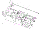


Landscapes
- Cleaning By Liquid Or Steam (AREA)
Abstract
The utility model relates to an automatic cleaning device which comprises a workbench (1), a first material moving mechanism (2), a feeding mechanism (3), a material pulling mechanism (4), a placing plate (5) and a cleaning mechanism (6); the feeding mechanism (3) is used for conveying the feeding plate (100), the first material moving mechanism (2) is used for adsorbing the feeding plate (100) from the feeding mechanism (3) and placing the feeding plate on the placing plate (5), the placing plate (5) is positioned at the driving end of the material pulling mechanism (4), and the cleaning mechanism (6) spans the material pulling mechanism (4) and is used for cleaning the feeding plate (100).
Description
Technical Field
The utility model relates to the technical field of automation, in particular to an automatic cleaning device.
Background
The metal plate coated with the glue needs to be recycled and reused, and the glue on the surface needs to be removed, and the traditional treatment method is generally divided into two types, wherein one type is that after the metal plate is placed into alcohol for soaking, the metal plate is taken out and then the glue is scraped, and the other type is that the glue is directly removed by a scraper. The first method is cumbersome to process, and the related procedures comprise soaking, cleaning, salvaging, separating and other operations, so that the multi-processing time of the procedures is long. The second method described above also causes a problem that the glue is difficult to remove because the glue is not subjected to a preliminary treatment. In the prior art, the second method is adopted to realize automation, and the metal plates are processed through the feeding mechanism, the conveying mechanism and the scraper mechanism, but in the process of realizing automation, firstly, the conveying distance of the feeding mechanism cannot be adjusted, only the metal plates with fixed sizes can be conveyed, and secondly, the metal plates are difficult to clean in the scraper procedure.
Disclosure of Invention
In order to solve the technical problems, the utility model aims to provide a device which can completely realize automation and can separate and clean glue from a metal plate.
The technical scheme of the utility model is as follows:
an automatic cleaning device comprises a workbench (1), a first material moving mechanism (2), a feeding mechanism (3), a material pulling mechanism (4), a placing plate (5) and a cleaning mechanism (6); wherein the feeding mechanism (3) is used for conveying a feeding plate (100), the first material moving mechanism (2) is used for adsorbing the feeding plate (100) from the feeding mechanism (3) and placing the feeding plate on the placing plate (5), the placing plate (5) is positioned on the driving end of the material pulling mechanism (4), and the cleaning mechanism (6) spans the material pulling mechanism (4) and is used for cleaning the feeding plate (100);
the cleaning mechanism (6) comprises a cleaning support (601) arranged on the workbench (1), a lower pressing cylinder (602) is arranged at the top of the cleaning support (601), a lower pressing head (6021) is connected with the driving end of the lower pressing cylinder (602), a second sliding rail (603) is further arranged on one side face of the cleaning support (601), a mounting frame (604) is connected to the second sliding rail (603) in a sliding mode, a scraper (608) is connected to the mounting frame (604) in a sliding mode, an alcohol tank (609) and a cleaning roller (610) are further arranged on the other side of the cleaning support (601) up and down, and the material pulling mechanism (4) pulls the material plate (100) to be immersed in alcohol through the cleaning roller (610) to be cleaned by the scraper (608).
Further, arc grooves (6041) are formed in side plates on two sides of the mounting frame (604), the arc grooves (6041) are connected with adjusting plates (605) located in the mounting frame (604) through fastening screws (6042), scraper lower clamping plates (606) are connected to the adjusting plates (605), scraper upper clamping plates (607) are connected to the scraper lower clamping plates (606), and the scraper (608) is connected between the scraper lower clamping plates (606) and the scraper upper clamping plates (607).
Further, feeding mechanism (3) is including setting up to a set of first slide rail (301) on workstation (1), be provided with two sliders (302) on first slide rail (301), sliding connection has side frame board (303) on slider (302), still be provided with screw mechanism (304) on workstation (1), screw (3041) of screw mechanism (304) are connected to in screw sleeve (3031) of side frame board (303), both sides all are provided with belt pulley (307) on the side frame board, be provided with belt (305) between belt pulley (307), still be provided with driving motor (306) on workstation (1), driving motor (306) drive connection driving roller (309), driving roller (309) cup joint on clamping wheel (308) in belt pulley (307), be provided with spout (3091) on driving roller (309).
Further, the first material moving mechanism (2) comprises a first material moving frame (201) fixedly arranged on the workbench (1), a first air cylinder (202) horizontally arranged on the first material moving frame (201), a second air cylinder (203) vertically arranged at the driving end of the first air cylinder (202), a first mounting plate (204) connected to the driving end of the second air cylinder (203), and a plurality of first adsorption heads (205) connected to the first mounting plate (204).
Further, the material pulling mechanism (4) comprises a material pulling support (401) fixedly arranged on the workbench (1), and a material pulling cylinder (402) connected to the material pulling support (401).
Further, the device also comprises a second material moving mechanism (7) for moving the cleaned material plate (100) and a discharging mechanism (8) for conveying the cleaned material plate (100).
Further, the second material moving mechanism (7) comprises a second material moving frame (701) arranged on the workbench (1), a third air cylinder (702) horizontally arranged on the second material moving frame (701), a connecting plate (703) connected to the driving end of the third air cylinder (702) and vertically arranged, a fourth air cylinder (704) connected to the connecting plate (703), a second mounting plate (705) connected to the driving end of the fourth air cylinder (704), and a plurality of second adsorption heads (706) connected to the second mounting plate (705).
Further, the discharging mechanism (8) comprises a discharging support (801) fixedly arranged on the workbench (1), a conveying belt (802) connected to the discharging support (801), a conveying motor (803) is arranged at the bottom of the discharging support (801), and the conveying motor (803) is connected with a conveying roller (805) of the conveying belt (802) through a conveying belt (804).
By means of the scheme, the utility model has at least the following advantages:
(1) The feeding mechanism of the device can adjust the distance between the two side frame plates through the screw rod mechanism, so that the feeding of the material plates with different sizes can be realized;
(2) The cleaning mechanism of the device is provided with the cleaning roller of the alcohol tank box, so that the surface of the material plate can be immersed in alcohol, and the glue can be scraped more conveniently;
(3) The angle of the scraper can be adjusted according to the installation angle of the arc-shaped groove and the installation frame in the cleaning mechanism of the device, so that the surface treatment of the material plate is facilitated.
The foregoing description is only an overview of the present utility model, and is intended to provide a better understanding of the present utility model, as it is embodied in the following description, with reference to the preferred embodiments of the present utility model and the accompanying drawings.
Drawings
FIG. 1 is a top view of the present utility model;
FIG. 2 is a schematic perspective view of the present utility model;
FIG. 3 is a schematic perspective view of a first material moving mechanism and a material feeding mechanism according to the present utility model;
FIG. 4 is a top view of a first feed mechanism and feed mechanism of the present utility model;
FIG. 5 is a schematic perspective view of a feeding mechanism according to the present utility model;
FIG. 6 is a schematic perspective view of a cleaning mechanism of the present utility model;
FIG. 7 is a side view of the cleaning mechanism of the present utility model;
FIG. 8 is a schematic perspective view of a second material moving mechanism and a material discharging mechanism;
FIG. 9 is a schematic diagram II of a second perspective view of a second material moving mechanism and a discharge mechanism of the present utility model;
in the figure:
100-material plates;
1-a workbench;
2-a first material moving mechanism; 201-a first material moving frame; 202-a first cylinder; 203-a second cylinder; 204-a first mounting plate; 205-a first adsorption head;
3-a feeding mechanism; 301-a first slide rail; 302-a slider; 303-side frame plates; 3031-a screw sleeve; 304-a screw mechanism; 3041-a screw; 305-a belt; 306-a drive motor; 307-pulleys; 308-clamping wheels; 309-driving roller; 3091-chute;
4-a material pulling mechanism; 401-pulling a material bracket; 402-a material pulling cylinder;
5-placing a plate;
6-a cleaning mechanism; 601-cleaning a rack; 602-pressing down a cylinder; 6021-lower ram; 603-a second slide rail; 604-a mounting frame; 6041-arcuate slot; 6042-fastening screw; 605-an adjustment plate; 606-doctor lower plate; 607-scraper upper clamp plate; 608—doctor blade; 609-alcohol tank; 610-cleaning rollers;
7-a second material moving mechanism; 701-a second material moving frame; 702-a third cylinder; 703-connecting plates; 704-a fourth cylinder; 705-a second mounting plate; 706-a second adsorption head;
8-a discharging mechanism; 801-a discharge bracket; 802-transmission band; 803-a transmission motor; 804-a conveyor belt; 805-transfer rolls.
Detailed Description
The following describes in further detail the embodiments of the present utility model with reference to the drawings and examples. The following examples are illustrative of the utility model and are not intended to limit the scope of the utility model.
Referring to fig. 1-9, an automatic cleaning device according to a preferred embodiment of the present utility model includes a workbench 1, a first material moving mechanism 2, a feeding mechanism 3, a material pulling mechanism 4, a placing plate 5, and a cleaning mechanism 6, wherein the feeding mechanism 3 is used for conveying a feeding plate 100, the first material moving mechanism 2 is used for adsorbing the material plate 100 from the feeding mechanism 3 and placing the material plate on the placing plate 5, the placing plate 5 is located at a driving end of the material pulling mechanism 4, the cleaning mechanism 6 spans the material pulling mechanism 4 and is used for cleaning the material plate 100, and the automatic cleaning device further includes a second material moving mechanism 7 for moving the cleaned material plate 100, and a discharging mechanism 8 for conveying the cleaned material plate 100.
The first material moving mechanism 2 includes a first material moving frame 201 fixedly provided to the table 1, a first cylinder 202 horizontally provided to the first material moving frame 201, a second cylinder 203 vertically provided to a driving end of the first cylinder 202, a first mounting plate 204 connected to a driving end of the second cylinder 203, and a plurality of first adsorption heads 205 connected to the first mounting plate 204. The first material moving mechanism 2 plays a role of adsorbing the material plate 100 and realizing the transverse movement of the material plate 100, the adsorption is realized through four first adsorption heads 205, the transverse movement is realized through a first air cylinder 202, and the second air cylinder 203 mainly realizes the up-and-down movement of the first adsorption heads 205.
The feeding mechanism 3 comprises a group of first sliding rails 301 arranged on the workbench 1, two sliding blocks 302 are arranged on the first sliding rails 301, a side frame plate 303 is connected to the sliding blocks 302 in a sliding manner, a screw rod mechanism 304 is further arranged on the workbench 1, a screw rod 3041 of the screw rod mechanism 304 is connected to a screw rod sleeve 3031 of the side frame plate 303, belt pulleys 307 are arranged on two sides of the side frame plate, a belt 305 is arranged between the belt pulleys 307, a driving motor 306 is further arranged on the workbench 1, a driving roller 309 is connected with the driving motor 306 in a driving manner, the driving roller 309 is sleeved on a clamping wheel 308 in the belt pulleys 307, and a sliding groove 3091 is formed in the driving roller 309. The screw rod mechanism 304 in the feeding mechanism 3 can drive the screw rod sleeve 3031 to move through the screw rod 3041, so that the distance between the two side frame plates 303 can be changed, and the feeding of the material plates 100 with different sizes can be realized. The driving motor 306 can drive the belt pulley 307 to rotate, and the chute 3091 arranged on the driving roller 309 can enable the clamping wheel 308 to slide on the chute, so that power transmission after movement can be realized.
The drawing mechanism 4 includes a drawing bracket 401 fixedly provided to the table 1, a drawing cylinder 402 connected to the drawing bracket 401, and the drawing mechanism 4 is a conventional mechanism.
The cleaning mechanism 6 comprises a cleaning support 601 arranged on the workbench 1, a lower pressing cylinder 602 is arranged at the top of the cleaning support 601, a lower pressing head 6021 is connected with the driving end of the lower pressing cylinder 602, a second sliding rail 603 is further arranged on one side face of the cleaning support 601, a mounting frame 604 is connected to the second sliding rail 603 in a sliding mode, the lower pressing head 6021 is connected with the mounting frame 604, a scraper 608 is connected to the mounting frame 604, an alcohol tank 609 and a cleaning roller 610 are further arranged on the other side of the cleaning support 601 up and down, and the material pulling mechanism 4 pulls a material plate 100 to be immersed in alcohol through the cleaning roller 610 and then to clean the surface through the scraper 608. The main function of the cleaning mechanism 6 is to fill the cleaning roller 610 with alcohol through the alcohol tank 609, the surface of the material plate 100 is coated with alcohol when the material plate 100 passes through the cleaning roller 610, and after the angle of the scraper 608 is set through the mounting frame, the glue on the surface of the material plate 100 is hung 608 to be cleaned.
The second material moving mechanism 7 includes a second material moving frame 701 provided to the table 1, a third cylinder 702 provided to the second material moving frame 701 and horizontally provided, a connection plate 703 vertically provided to a driving end of the third cylinder 702, a fourth cylinder 704 connected to the connection plate 703, a second mounting plate 705 connected to a driving end of the fourth cylinder 704, and a plurality of second adsorption heads 706 connected to the second mounting plate 705. The second material moving mechanism 7 and the first material moving mechanism 2 are consistent in principle, and both the actions of transverse movement and adsorption are realized.
The discharging mechanism 8 comprises a discharging support 801 fixedly arranged on the workbench 1, a conveying belt 802 connected to the discharging support 801, a conveying motor 803 arranged at the bottom of the discharging support 801, and a conveying roller 805 connected with the conveying belt 802 through the conveying belt 804, wherein the discharging mechanism 8 mainly receives and conveys the material plate 100 conveyed by the second material moving mechanism 7.
The utility model has the following advantages:
(1) The feeding mechanism of the device can adjust the distance between the two side frame plates through the screw rod mechanism, so that the feeding of the material plates with different sizes can be realized;
(2) The cleaning mechanism of the device is provided with the cleaning roller of the alcohol tank box, so that the surface of the material plate can be immersed in alcohol, and the glue can be scraped more conveniently;
(3) The angle of the scraper can be adjusted according to the installation angle of the arc-shaped groove and the installation frame in the cleaning mechanism of the device, so that the surface treatment of the material plate is facilitated.
The above description is only of the preferred embodiments of the present utility model and is not intended to limit the present utility model, and it should be noted that it is possible for those skilled in the art to make several improvements and modifications without departing from the technical principle of the present utility model, and these improvements and modifications should also be regarded as the protection scope of the present utility model.
Claims (8)
1. An automatic cleaning device, characterized in that: comprises a workbench (1), a first material moving mechanism (2), a feeding mechanism (3), a material pulling mechanism (4), a placing plate (5) and a cleaning mechanism (6); wherein the feeding mechanism (3) is used for conveying a feeding plate (100), the first material moving mechanism (2) is used for adsorbing the feeding plate (100) from the feeding mechanism (3) and placing the feeding plate on the placing plate (5), the placing plate (5) is positioned on the driving end of the material pulling mechanism (4), and the cleaning mechanism (6) spans the material pulling mechanism (4) and is used for cleaning the feeding plate (100);
the cleaning mechanism (6) comprises a cleaning support (601) arranged on the workbench (1), a lower pressing cylinder (602) is arranged at the top of the cleaning support (601), a lower pressing head (6021) is connected with the driving end of the lower pressing cylinder (602), a second sliding rail (603) is further arranged on one side face of the cleaning support (601), a mounting frame (604) is connected to the second sliding rail (603) in a sliding mode, a scraper (608) is connected to the mounting frame (604) in a sliding mode, an alcohol tank (609) and a cleaning roller (610) are further arranged on the other side of the cleaning support (601) up and down, and the material pulling mechanism (4) pulls the material plate (100) to be immersed in alcohol through the cleaning roller (610) to be cleaned by the scraper (608).
2. An automatic cleaning device according to claim 1, wherein: arc grooves (6041) are formed in side plates on two sides of the mounting frame (604), the arc grooves (6041) are connected with adjusting plates (605) located in the mounting frame (604) through fastening screws (6042), scraper lower clamping plates (606) are connected to the adjusting plates (605), scraper upper clamping plates (607) are connected to the scraper lower clamping plates (606), and the scraper (608) is connected between the scraper lower clamping plates (606) and the scraper upper clamping plates (607).
3. An automatic cleaning device according to claim 1, wherein: feeding mechanism (3) are including setting up to a set of first slide rail (301) on workstation (1), be provided with two sliders (302) on first slide rail (301), sliding connection has side frame board (303) on slider (302), still be provided with screw mechanism (304) on workstation (1), screw (3041) of screw mechanism (304) are connected to in screw sleeve (3031) of side frame board (303), both sides all are provided with belt pulley (307) on the side frame board, be provided with belt (305) between belt pulley (307), still be provided with driving motor (306) on workstation (1), driving motor (306) drive connection driving roller (309), driving roller (309) cup joint on clamping wheel (308) in belt pulley (307), be provided with spout (3091) on driving roller (309).
4. An automatic cleaning device according to claim 1, wherein: the first material moving mechanism (2) comprises a first material moving frame (201) fixedly arranged on the workbench (1), a first air cylinder (202) horizontally arranged on the first material moving frame (201), a second air cylinder (203) vertically arranged at the driving end of the first air cylinder (202), a first mounting plate (204) connected to the driving end of the second air cylinder (203), and a plurality of first adsorption heads (205) connected to the first mounting plate (204).
5. An automatic cleaning device according to claim 1, wherein: the material pulling mechanism (4) comprises a material pulling support (401) fixedly arranged on the workbench (1), and a material pulling cylinder (402) connected to the material pulling support (401).
6. An automatic cleaning device according to claim 1, wherein: the device also comprises a second material moving mechanism (7) for moving the cleaned material plate (100) and a discharging mechanism (8) for conveying the cleaned material plate (100).
7. An automatic cleaning device according to claim 6, wherein: the second material moving mechanism (7) comprises a second material moving frame (701) arranged on the workbench (1), a third air cylinder (702) horizontally arranged on the second material moving frame (701), a connecting plate (703) vertically arranged at the driving end of the third air cylinder (702), a fourth air cylinder (704) connected to the connecting plate (703), a second mounting plate (705) connected to the driving end of the fourth air cylinder (704), and a plurality of second adsorption heads (706) connected to the second mounting plate (705).
8. An automatic cleaning device according to claim 6, wherein: the discharging mechanism (8) comprises a discharging support (801) fixedly arranged on the workbench (1), a conveying belt (802) connected to the discharging support (801), a conveying motor (803) is arranged at the bottom of the discharging support (801), and the conveying motor (803) is connected with a conveying roller (805) of the conveying belt (802) through a conveying belt (804).
Priority Applications (1)
| Application Number | Priority Date | Filing Date | Title |
|---|---|---|---|
| CN202223189089.XU CN218963370U (en) | 2022-11-30 | 2022-11-30 | Automatic cleaning device |
Applications Claiming Priority (1)
| Application Number | Priority Date | Filing Date | Title |
|---|---|---|---|
| CN202223189089.XU CN218963370U (en) | 2022-11-30 | 2022-11-30 | Automatic cleaning device |
Publications (1)
| Publication Number | Publication Date |
|---|---|
| CN218963370U true CN218963370U (en) | 2023-05-05 |
Family
ID=86148914
Family Applications (1)
| Application Number | Title | Priority Date | Filing Date |
|---|---|---|---|
| CN202223189089.XU Active CN218963370U (en) | 2022-11-30 | 2022-11-30 | Automatic cleaning device |
Country Status (1)
| Country | Link |
|---|---|
| CN (1) | CN218963370U (en) |
Cited By (1)
| Publication number | Priority date | Publication date | Assignee | Title |
|---|---|---|---|---|
| CN118988914A (en) * | 2024-09-18 | 2024-11-22 | 深圳清大电子科技有限公司 | Saving type glass cover plate cleaning equipment |
-
2022
- 2022-11-30 CN CN202223189089.XU patent/CN218963370U/en active Active
Cited By (1)
| Publication number | Priority date | Publication date | Assignee | Title |
|---|---|---|---|---|
| CN118988914A (en) * | 2024-09-18 | 2024-11-22 | 深圳清大电子科技有限公司 | Saving type glass cover plate cleaning equipment |
Similar Documents
| Publication | Publication Date | Title |
|---|---|---|
| CN211940344U (en) | Sheet metal surface treatment equipment | |
| CN213558626U (en) | Paster surface cleaning device for high-speed paster machine | |
| CN105835121A (en) | Die-cutting machine of packaging box | |
| CN212886033U (en) | Straightening machine | |
| CN216801916U (en) | Aluminum plate continuous cutting device | |
| CN211758120U (en) | Feeding device for hardware processing | |
| CN207605933U (en) | A kind of apparatus for coating of cold light film dielectric layer | |
| CN223221855U (en) | Glass mildew-proof powder rubbing powder recovery device | |
| CN223877713U (en) | A device for printing patterns on the surface of high-resilience and abrasion-resistant bag leather | |
| CN221658810U (en) | Soft magnetic ferrite magnetic core unburned bricks unhairing limit device | |
| CN114633452A (en) | A method for processing material heads in the production and processing of extruded end-corrected polyvinyl chloride pipes | |
| CN218690971U (en) | Coating device of lithium battery transfer type coating machine | |
| CN219325324U (en) | Board edge cleaning equipment | |
| CN214688408U (en) | Compounding machine capable of being firmly pasted | |
| CN213353541U (en) | Precleaning type decorative board pad pasting device in advance | |
| CN223250658U (en) | Formed steel burr cutting device | |
| CN220279151U (en) | A burr removal device for hot-dip galvanizing production | |
| CN223701881U (en) | An adjustable modular foam press | |
| CN221474544U (en) | Grinding device for sheet stamping part | |
| CN220534475U (en) | Bamboo article sharpeners | |
| CN218557436U (en) | Double-station green removing fluffer | |
| CN224143678U (en) | Chip removal device of nut tapping machine | |
| CN223160640U (en) | Aluminum profile plane polishing device | |
| CN215556327U (en) | Separator of panel cut edge clout | |
| CN223698324U (en) | Gluing device for processing high polymer material |
Legal Events
| Date | Code | Title | Description |
|---|---|---|---|
| GR01 | Patent grant | ||
| GR01 | Patent grant |