CN218956245U - Beam pulling-on piece mechanism - Google Patents
Beam pulling-on piece mechanism Download PDFInfo
- Publication number
- CN218956245U CN218956245U CN202223250748.6U CN202223250748U CN218956245U CN 218956245 U CN218956245 U CN 218956245U CN 202223250748 U CN202223250748 U CN 202223250748U CN 218956245 U CN218956245 U CN 218956245U
- Authority
- CN
- China
- Prior art keywords
- tab
- pull
- motor
- adjusting
- pulling
- Prior art date
- Legal status (The legal status is an assumption and is not a legal conclusion. Google has not performed a legal analysis and makes no representation as to the accuracy of the status listed.)
- Active
Links
- 230000007246 mechanism Effects 0.000 title claims abstract description 15
- 230000001360 synchronised effect Effects 0.000 claims abstract description 22
- 230000001105 regulatory effect Effects 0.000 claims description 11
- 229910000831 Steel Inorganic materials 0.000 claims description 4
- 239000010959 steel Substances 0.000 claims description 4
- 230000004075 alteration Effects 0.000 description 1
- 230000009286 beneficial effect Effects 0.000 description 1
- 230000008859 change Effects 0.000 description 1
- 238000000034 method Methods 0.000 description 1
- 238000012986 modification Methods 0.000 description 1
- 230000004048 modification Effects 0.000 description 1
- 230000008569 process Effects 0.000 description 1
- 238000009662 stress testing Methods 0.000 description 1
- 238000006467 substitution reaction Methods 0.000 description 1
Images

Landscapes
- Manufacture Of Motors, Generators (AREA)
Abstract
The utility model belongs to the field of beam pull-tab mechanisms, and in particular relates to a beam pull-tab mechanism which comprises a beam, a synchronous width adjusting motor, a supporting adjusting plate, a pull-tab motor, a pull-tab rotating shaft, an adjusting screw rod and a pull-tab tooth tip chain. According to the utility model, synchronous width adjustment of the cross beams is realized by arranging synchronous width adjustment motors at two ends of the cross beams, and the pull-tab motor drives the pull-tab rotating shafts to enable the pull-tab tooth tip chains in the two cross beams to circularly rotate so as to realize pull-tab conveying.
Description
Technical Field
The utility model relates to the technical field of beam pull-tab mechanisms, in particular to a beam pull-tab mechanism.
Background
The utility model patent with the publication number of CN 217111818U discloses a net stretching movable cross beam assembly, which comprises a main body, a first sliding block fixedly arranged on the end face of a first end of the main body, a second sliding block fixedly arranged on the end face of a second end of the main body, a sliding rail fixedly arranged on the inner side wall of the main body and parallel to the length direction of the main body, a sliding connecting piece which is slidably arranged on the sliding rail and is used for being connected with a net, and a driving device which is rotatably connected with the outer side wall of the main body and is used for pushing the main body to move. When the net sheet stretching movable cross beam assembly is used, the main body is pushed to move by the driving device until the main body drives the sliding rail and the sliding connecting piece to move to the position of the end part of the net sheet, then the end part of the net sheet is connected with the sliding connecting piece on the sliding rail, the sliding connecting piece on the sliding rail can be adjusted in a sliding mode according to the distance between net steel at the end part of the net sheet, and after connection is completed, stress testing can be conducted on the net sheet. However, in the prior art, the distance between the cross beams is fixed, the adjustment cannot be performed, and the device is inconvenient to use. Accordingly, improvements in the art are needed.
Disclosure of Invention
The utility model aims to provide a beam pull-tab mechanism, which solves the problems that the interval between beams is fixed, the adjustment cannot be carried out, and the device is inconvenient to use.
In order to achieve the above purpose, the present utility model provides the following technical solutions: the utility model provides a crossbeam pulling-on piece mechanism, includes crossbeam, synchronous width adjusting motor, supports regulating plate, pulling-on piece motor, pulling-on piece pivot, accommodate the lead screw, pulling-on piece prong chain, be provided with on the crossbeam and support the regulating plate, be provided with accommodate the lead screw on the synchronous width adjusting motor, accommodate the lead screw and support the regulating plate and pass through threaded connection, fixed mounting has the pulling-on piece motor on the support regulating plate, be provided with the pulling-on piece pivot on the pulling-on piece motor, pulling-on piece pivot and support regulating plate rotate and connect, be provided with pulling-on piece prong chain in the crossbeam.
Preferably, the number of the synchronous width adjusting motors is two, and the two synchronous width adjusting motors are symmetrically distributed on the cross beam. Through setting up synchronous width motor for the interval is convenient for adjust between two crossbeams.
Preferably, a gear is arranged on the pull-tab rotating shaft, and the gear is meshed with the pull-tab tooth tip chain. Through setting up the pulling-on piece pivot, can drive pulling-on piece tooth point chain and remove.
Preferably, two supporting adjusting plates are arranged on the outer side of the adjusting screw rod, and the two supporting adjusting plates are symmetrically distributed on the adjusting screw rod. Through setting up the support regulating plate, adjust lead screw and crossbeam and connect.
Preferably, a spline is arranged on the outer side of the pull-tab rotating shaft, a connecting sleeve is connected to the spline in a sliding mode, the connecting sleeve is connected with the supporting adjusting plate in a rotating mode, and the connecting sleeve is connected with the pull-tab rotating shaft in a sliding mode. The opposite pull-tab rotating shaft is connected with the connecting sleeve through the spline.
Preferably, the cross beam is of a hollow structure, and the cross beam is made of steel. Through setting up the crossbeam, to pulling-on piece tooth point chain connection.
Compared with the prior art, the utility model has the following beneficial effects:
according to the utility model, synchronous width adjustment of the cross beams is realized by arranging synchronous width adjustment motors at two ends of the cross beams, and the pull-tab motor drives the pull-tab rotating shafts to enable the pull-tab tooth tip chains in the two cross beams to circularly rotate so as to realize pull-tab conveying.
Drawings
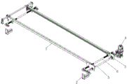
FIG. 1 is a perspective view of the overall structure of the present utility model;
fig. 2 is a partial view of the beam of fig. 1 in accordance with the present utility model.
In the figure: 1. a cross beam; 2. synchronous width adjusting motor; 3. supporting an adjusting plate; 4. a pull tab motor; 5. a pull-tab spindle; 6. adjusting a screw rod; 7. pull tab tooth tip chain.
Detailed Description
The following description of the embodiments of the present utility model will be made clearly and completely with reference to the accompanying drawings, in which it is apparent that the embodiments described are only some embodiments of the present utility model, but not all embodiments. All other embodiments, which can be made by those skilled in the art based on the embodiments of the utility model without making any inventive effort, are intended to be within the scope of the utility model.
Referring to fig. 1 and 2, a beam pull-tab mechanism includes a beam 1, a synchronous width adjusting motor 2, a supporting adjusting plate 3, a pull-tab motor 4, a pull-tab rotating shaft 5, an adjusting screw 6 and a pull-tab tooth tip chain 7, wherein the supporting adjusting plate 3 is arranged on the beam 1, the adjusting screw 6 is arranged on the synchronous width adjusting motor 2, two supporting adjusting plates 3 are symmetrically distributed on the adjusting screw 6, the adjusting screw 6 and the beam 1 are connected by arranging the supporting adjusting plates 3, the synchronous width adjusting motor 2 is two, the synchronous width adjusting motor 2 is symmetrically distributed on the beam 1, the distance between the two beams 1 is convenient to adjust by arranging the synchronous width adjusting motor 2, the adjusting screw 6 and the supporting adjusting plate 3 are connected through threads, the pull-tab motor 4 is fixedly arranged on the supporting adjusting plate 3, and the pull-tab rotating shaft 5 is arranged on the pull-tab motor 4.
Referring to fig. 1 and 2, a spline is arranged on the outer side of a pull-tab rotating shaft 5, a connecting sleeve is connected to the spline in a sliding manner, the connecting sleeve is connected with a supporting adjusting plate 3 in a rotating manner, the connecting sleeve is connected with the pull-tab rotating shaft 5 in a sliding manner, a gear is arranged on the pull-tab rotating shaft 5 and is meshed with a pull-tab tooth tip chain 7, the pull-tab tooth tip chain 7 can be driven to move by arranging the pull-tab rotating shaft 5, the pull-tab rotating shaft 5 is connected with the supporting adjusting plate 3 in a rotating manner, the pull-tab tooth tip chain 7 is arranged in a cross beam 1, the cross beam 1 is of a hollow structure, and the cross beam 1 is made of steel and is connected with the pull-tab tooth tip chain 7 by arranging the cross beam 1.
The specific implementation process of the utility model is as follows: during the use, through starting synchronous width adjustment motor 2 drive accommodate lead screw 6 rotation, accommodate lead screw 6 rotates and supports adjusting plate 3 and do the screw thread motion, and then make interval change between two crossbeams 1, realize crossbeam 1 synchronous width adjustment, then start tab motor 4, tab motor 4 starts drive tab pivot 5 rotation, and tab pivot 5 rotates drive tab tooth point chain 7 and removes, and then makes the tab carry.
Although embodiments of the present utility model have been shown and described, it will be understood by those skilled in the art that various changes, modifications, substitutions and alterations can be made therein without departing from the principles and spirit of the utility model, the scope of which is defined in the appended claims and their equivalents.
Claims (6)
1. The utility model provides a crossbeam pulling-on piece mechanism, includes crossbeam (1), synchronous width-adjusting motor (2), supports regulating plate (3), pulling-on piece motor (4), pulling-on piece pivot (5), accommodate lead screw (6), pulling-on piece tooth point chain (7), its characterized in that: be provided with on crossbeam (1) and support regulating plate (3), be provided with accommodate the lead screw (6) on synchronous wide motor (2), accommodate the lead screw (6) and support regulating plate (3) through threaded connection, fixed mounting has pull tab motor (4) on supporting regulating plate (3), be provided with pull tab pivot (5) on pull tab motor (4), pull tab pivot (5) and support regulating plate (3) rotate and connect, be provided with pull tab tooth point chain (7) in crossbeam (1).
2. A beam tab mechanism as defined in claim 1, wherein: the synchronous width adjusting motors (2) are two, and the two synchronous width adjusting motors (2) are symmetrically distributed on the cross beam (1).
3. A beam tab mechanism as defined in claim 1, wherein: the pull-tab rotating shaft (5) is provided with a gear, and the gear is meshed with the pull-tab tooth tip chain (7).
4. A beam tab mechanism as defined in claim 1, wherein: two support adjusting plates (3) are arranged on the outer side of the adjusting screw rod (6), and the two support adjusting plates (3) are symmetrically distributed on the adjusting screw rod (6).
5. A beam tab mechanism as defined in claim 1, wherein: the outer side of the pull-tab rotating shaft (5) is provided with a spline, the spline is connected with a connecting sleeve in a sliding mode, the connecting sleeve is connected with the support adjusting plate (3) in a rotating mode, and the connecting sleeve is connected with the pull-tab rotating shaft (5) in a sliding mode.
6. A beam tab mechanism as defined in claim 1, wherein: the beam (1) is of a hollow structure, and the beam (1) is made of steel.
Priority Applications (1)
| Application Number | Priority Date | Filing Date | Title |
|---|---|---|---|
| CN202223250748.6U CN218956245U (en) | 2022-12-06 | 2022-12-06 | Beam pulling-on piece mechanism |
Applications Claiming Priority (1)
| Application Number | Priority Date | Filing Date | Title |
|---|---|---|---|
| CN202223250748.6U CN218956245U (en) | 2022-12-06 | 2022-12-06 | Beam pulling-on piece mechanism |
Publications (1)
| Publication Number | Publication Date |
|---|---|
| CN218956245U true CN218956245U (en) | 2023-05-02 |
Family
ID=86110957
Family Applications (1)
| Application Number | Title | Priority Date | Filing Date |
|---|---|---|---|
| CN202223250748.6U Active CN218956245U (en) | 2022-12-06 | 2022-12-06 | Beam pulling-on piece mechanism |
Country Status (1)
| Country | Link |
|---|---|
| CN (1) | CN218956245U (en) |
-
2022
- 2022-12-06 CN CN202223250748.6U patent/CN218956245U/en active Active
Similar Documents
| Publication | Publication Date | Title |
|---|---|---|
| CN112676377A (en) | Winding mechanism capable of adjusting winding speed and used for copper strip calendering | |
| CN220049845U (en) | Spring steel wire straightener | |
| CN116117029B (en) | Full-automatic split type stator coil numerical control bending machine | |
| CN209255528U (en) | A kind of seamless steel tube straightening machine | |
| CN223475941U (en) | Battery aluminum shell material loading divides device that expands | |
| CN223582750U (en) | Twisting equipment for automobile wire harness production | |
| CN219623165U (en) | Transmission chain adjusting mechanism | |
| CN220021501U (en) | Rotatable adjustable distance busbar lap joint device | |
| CN221086792U (en) | Straightening device of motor shaft | |
| CN219484037U (en) | Cable straightening device | |
| CN224222380U (en) | Straightening device for stainless steel product processing | |
| CN223206051U (en) | Winding mechanism of adhesive tape winding machine | |
| CN222037011U (en) | A mechanism for manually lifting guide arms | |
| CN219529717U (en) | Gear reduction box locking fixed knot constructs | |
| CN222505780U (en) | A rack-type steering gear detection fixture | |
| CN220406767U (en) | Convenient type device of transferring of C shaped steel | |
| CN222370182U (en) | Panel alignment equipment | |
| CN223652119U (en) | Fixing clamp of motor stator wire binding machine | |
| CN223222244U (en) | Profile steel bending equipment | |
| CN222551744U (en) | Aluminum rod straightening machine and sizing device | |
| CN220151813U (en) | Speed reducer | |
| CN224026349U (en) | Straightener is used in galvanized wire production | |
| CN221657579U (en) | Straightening device for steel structure column beam | |
| CN215697553U (en) | Movable bending machine | |
| CN222642898U (en) | Motor shaft straightening device for motor production |
Legal Events
| Date | Code | Title | Description |
|---|---|---|---|
| GR01 | Patent grant | ||
| GR01 | Patent grant |