Background
With the vigorous development of industrial park construction, the production staff of resident enterprises are increased, and the number of non-motor vehicles in the park is also in a situation of rapid growth. The non-motor vehicle shed provides good protection space for parking, rain sheltering, sun screening and charging for vehicles, and the demand of the non-motor vehicle shed is also increasing.
The existing non-motor vehicle shed is various in form, but is not suitable for popularization in industrial parks. The concrete steps are as follows:
1. only can be parked on one side, the occupied area is large, and the land utilization rate is not high, as shown in fig. 6.
2. The lack of drainage facilities has poor rainwater drainage effect. A large amount of rainwater is easily collected on the ceiling, and cannot be discharged in time to cause corrosion of the shed body, as shown in fig. 7.
3. The single upright post has a single structure and poor stress stability, and has certain potential safety hazards, as shown in fig. 8.
The industrial park is various in type of non-motor vehicles, so that the light non-motor vehicle shed with the charging piles is required to be provided, the parking and charging problems of the park can be effectively solved, meanwhile, the structure is simple, the structure is attractive, light, firm and durable, energy conservation and environmental protection are realized, the size is adjustable, and the modular design is convenient.
Disclosure of Invention
The utility model aims to solve the technical problems that: how to make the non-motor vehicle shed meet the parking and charging requirements of the battery car, ensure simple structure, attractive appearance, light weight, firmness, durability, energy conservation, environmental protection, adjustable size and convenient modularized design.
In order to solve the technical problems, the technical scheme of the utility model provides a double-cantilever type non-motorized vehicle shed with a charging pile, which is characterized by comprising a plurality of groups of supporting frames, wherein each group of supporting frames consists of a plurality of supporting frames, each supporting frame comprises a stand column, a supporting beam, two cantilever beams and a plurality of cross bars, the bottom of the stand column is fixed on a lower foundation, and the upper part of the stand column is in a Y-shaped structure to form a stable double-cantilever symmetrical structure; the support beam is of an inverted U-shaped structure and is positioned at the center of the upper side of the upright post, and support legs at two ends are fixedly connected with the upright post; the two cantilever beams are symmetrically arranged and respectively positioned at the upper part of the Y-shaped structure of the upright post and are fixedly connected with the upright post and the supporting beam; each cantilever beam is vertically provided with a plurality of cross bars;
the cross bars of the cantilever beams at the two sides of the multiple groups of support frames are respectively provided with a shed board, the support beams in the middle of the multiple groups of support frames are provided with a drainage ditch, the drainage ditch is arranged right below the middles of the shed boards at the two sides, and the bottoms of the drainage ditches are communicated with the multiple downpipes; the ground-mounted charging pile also comprises a plurality of charging piles fixed on the ground.
Preferably, two sides of each group of supporting frames are provided with a charging pile.
Preferably, two sides of each group of supporting frames are provided with a downpipe.
Preferably, the bottom of the drainage ditch is positioned right above the supporting beam, and the folded edges at the two ends of the drainage ditch are fixed with the cantilever beam and are pressed under the shed board.
Preferably, the outer side end part of the shed board and the outer side end part of the cantilever beam are respectively sealed and closed by the edge sealing plate and fixedly connected.
Preferably, the edge sealing plate is fixedly connected with the cantilever beam and the end part of the shed plate through angle steel and self-tapping screws.
Preferably, the shed board and the cross rod are fixedly connected in a sealing way through a rubber pad and a self-tapping screw.
Preferably, the upright post consists of double steel pipes, the lower parts of the double steel pipes are tightly welded and attached, and the upper parts of the double steel pipes are Y-shaped.
Preferably, the middle positions of the cantilever beams on two sides of the multiple groups of support frames are fixedly connected with Y-shaped bifurcation welding on two sides of the upper part of the upright post respectively.
Preferably, the inner side ends of the cantilever beams on two sides of the multiple groups of support frames are bent downwards to be fixedly connected with the support beams, so that grooves are formed, and the drainage ditches are arranged in the grooves.
Compared with the prior art, the utility model has the following beneficial effects:
by adopting the technical scheme provided by the utility model, the Y-shaped upright posts are positioned in the middle, and the cantilever beams are arranged at the two sides of the Y-shaped upright posts to form the upright post double-cantilever type awning, so that the using area and the using efficiency of the awning are increased; meanwhile, through reasonable combination of the supporting beam and the cantilever beam, a central drainage ditch is innovatively arranged, so that the non-motor vehicle can be parked to realize compact arrangement of single-column double-row parking, and the problem of water accumulation or unorganized drainage of the ceiling is effectively avoided; and the charging pile design is combined, so that the application range is wider. Meanwhile, the structure can be customized in a factory and unified mode, a single module can be copied according to the parking quantity requirement, and applicability, practicability and flexibility are greatly enhanced.
By using the steel plate as a ceiling, the ceiling is durable; the edge sealing plate is arranged at the key end part, so that the structure is more attractive and reasonable, and an effective structure meeting multiple performances such as efficient parking and strong applicability is formed.
The utility model forms an effective structure meeting multiple performances such as high-efficiency parking, strong applicability and the like through reasonable combination and collocation.
Detailed Description
In order to make the utility model more comprehensible, preferred embodiments accompanied with figures are described in detail below.
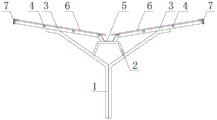
The utility model provides a double-cantilever type non-motor vehicle shed with charging piles, which is shown in fig. 1-5, and comprises a plurality of groups of supporting frames, wherein each group of supporting frames consists of a plurality of supporting frames, and each supporting frame comprises a stand column 1, a supporting beam 2, two cantilever beams 3 and a plurality of cross bars 4.
The upright post 1 is a supporting structure of the double-picking shed, the bottom is fixed on a lower foundation, and the upper part is of a Y-shaped structure, so that a stable double-picking symmetrical structure is formed.
The supporting beam 2 is a central supporting member and is of an inverted U-shaped structure, and is positioned at the central position of the upper side of the Y-shaped upright post 1, and supporting feet at two ends are welded with the upright post 1.
The cantilever beams 3 are symmetrically arranged left and right and are respectively positioned at the upper part of the Y-shaped structure of the upright post 1, and are welded and fixed with the support beam 2 and the upright post 1; and a plurality of cross bars 4 are vertically arranged on each cantilever beam 3.
The cross bar 4 is arranged vertically to the cantilever beam 3 and is a main supporting framework of the shed board 6.
The cross bars 4 of the cantilever beams 3 on two sides of the multiple groups of support frames are respectively provided with a shed board 6, the support beams 2 in the middle of the multiple groups of support frames are provided with a drainage ditch 5, the drainage ditch 5 is arranged right below the shed boards 6 on two sides, namely, the drainage ditch 5 is positioned at the center of the top surface of the shed, and the bottoms of the drainage ditches 5 are connected and communicated with a plurality of downpipes 9; and also comprises a plurality of charging piles 8 fixed on the ground.
The drainage ditch 5 is arranged at the bottom of the drainage ditch and is positioned right above the supporting beam 2, and folded edges at two ends of the drainage ditch are fixed with the cantilever beam 3 and are pressed under the shed board 6.
The roof panel 6 is a rain shielding member and guides the collected rainwater to collect in the drainage ditch 5.
The edge sealing plate 7 is an end fixing member and seals and closes the ends of the shed plate 6 and the cantilever beam 3.
The charging pile 8 is combined with the parking space, is matched with a professional manufacturer, and can be used for non-motor vehicles needing to be charged, such as a battery car.
A downpipe 9 connected to the drain 5 and introducing rainwater into the underground drainage facility.
Rubber pad 10, sealant layer 11 and self-tapping screw 13 are fixed with car canopy board 6 and horizontal pole 4, and self-tapping screw 13 one end passes car canopy board 6 in proper order, rubber pad 10 and horizontal pole 4 fixed connection to set up sealant layer 11 in the hookup location of self-tapping screw 13 and car canopy board 6. The edge sealing plate 7 is fixed with the cantilever beam 3 and the end part of the shed plate 6 through the angle steel 12 and the self-tapping screw 13, namely, the bending edge of the upper side of the edge sealing plate 7 is wrapped at the end part of the shed plate 6, the bending edge in the middle of the edge sealing plate 7 is wrapped at the end part of the cantilever beam 3, the bending edge of the lower side of the edge sealing plate 7 is inwards bent, the angle steel 12 is arranged between the bending edge in the middle of the edge sealing plate 7 and the end part of the cantilever beam 3, and one end of the self-tapping screw 13 sequentially passes through the bending edge in the middle of the edge sealing plate 7 and the angle steel 12 and then is fixedly connected with the end part of the cantilever beam 3.
The space between the upright posts 1, the height of the upright posts 1, the double-picking angle, the length and the like have preferable modulus requirements, and the factory unified customization is facilitated. The shed has the condition of modular production, takes the column spacing of 4.5 meters as a single module, can be continuously duplicated, and meets the requirements of different parking numbers. The upright post 1, the supporting beam 2, the cantilever beam 3 and the cross rod 4 are all round steel pipe components, and are the same in material and convenient to weld.
In the embodiment, the height of the lower part of the upright column 1 is 1.25 m, the net height of the side of the double-picking canopy plate is 2.4 m, and the inner low and high-end modeling is adopted, so that the height of the parking surface is ensured to be reasonable, and the steel consumption is greatly saved.
The upright posts 1 are composed of double steel pipes, the lower parts of the two upright posts are tightly welded and attached, the upper parts of the two upright posts are separated into Y-shaped, and the column spacing (namely the distance between two adjacent upright posts 1) is controlled to be 4.5 meters.
The middle positions of the cantilever beams 3 on the two sides are respectively and fixedly connected with Y-shaped forked branches on the two sides of the upper part of the upright post 1 in a welding way. The inner side ends of the cantilever beams 3 on two sides are bent downwards and welded with the supporting beams 2 to form grooves, so that the positions of the drainage ditches 5 are reserved, the depth is 600mm, sufficient rainwater collection capacity is guaranteed, and the drainage ditches 5 are arranged in the grooves.
In the embodiment, the
upright 1 is formed by two upright posts
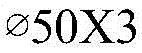
The steel pipe is formed by intermittent welding, preferably the length of the welding line is 200, the intermittent welding line is 200, and the Y-shaped welding line is preferably at an angle of 110 degrees. The
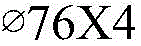
support beam 2 is +.>
The steel pipe is welded with the
upright column 1 and is in an inverted U shape, and the angle is preferably 110 degrees. The
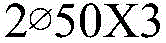
cantilever beam 3 adopts +.>
The width is chosen according to non-motor vehicle size preference 2.4 meters to steel pipe, two respectively at both ends, and
cantilever beam 3 and stand 1 and a supporting
beam 2 all weld. The
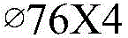
cross bar 4 adopts +.>
The steel pipes are welded with the
cantilever beam 3 vertically, and the spacing is preferably 750mm. The steel pipe components can be manufactured in a factory and unified mode, and are connected through welding, so that the overall structural strength and stability of the structure are ensured. The
drainage ditch 5 is preferably a 1.0 thick 304 stainless steel outer gutter, 1% of slope is found, the slope is welded with the
cantilever beam 3 in a flanging way, and the slope is pressed under the
carport plate 6, the flanging length of the
cantilever beam 3 determines the depth of the
drainage ditch 5, so that the flanging depth is required to be not less than 600mm, the collection of large-capacity rainwater is met, and meanwhile, the flanging and the triangular support of the
lower support beam 2 also play a good fixing role on the
drainage ditch 5. The
shed board 6 is preferably made of 0.6mm single-layer corrugated aluminized zinc color steel plateThe trough part is tightly fixed with the
cross rod 4 by adopting a
rubber pad 10, a sealing
glue layer 11 and a tapping
screw 13. The
edge sealing plate 7 is preferably an aluminized zinc color steel plate, the
angle steel 12 is arranged in a full length mode, the model L40X40X4 is preferred, and the
edge sealing plate 7, the
cantilever beam 3 and the end portion of the
shed plate 6 are fixed and edge-folded through the self-tapping
screw 13 and the
angle steel 12. The charging piles 8 are uniformly configured by professional manufacturers and selected by owners.
The steel structure upright post overhanging type non-motor vehicle shed adopts the steel structure upright post overhanging type structure, has small occupied area, reasonable stress and attractive appearance, and can meet the requirements of different types of projects on outdoor non-motor vehicle parking and actual use by arranging the charging pile device.