CN218946778U - Welding jig - Google Patents
Welding jig Download PDFInfo
- Publication number
- CN218946778U CN218946778U CN202223410858.4U CN202223410858U CN218946778U CN 218946778 U CN218946778 U CN 218946778U CN 202223410858 U CN202223410858 U CN 202223410858U CN 218946778 U CN218946778 U CN 218946778U
- Authority
- CN
- China
- Prior art keywords
- clamping
- clamping mechanism
- base
- sliding
- welding jig
- Prior art date
- Legal status (The legal status is an assumption and is not a legal conclusion. Google has not performed a legal analysis and makes no representation as to the accuracy of the status listed.)
- Active
Links
- 238000003466 welding Methods 0.000 title claims abstract description 52
- 230000007246 mechanism Effects 0.000 claims abstract description 124
- 230000000712 assembly Effects 0.000 claims description 25
- 238000000429 assembly Methods 0.000 claims description 25
- 238000003825 pressing Methods 0.000 claims description 8
- 238000001514 detection method Methods 0.000 claims description 7
- 230000001360 synchronised effect Effects 0.000 abstract description 7
- 230000009286 beneficial effect Effects 0.000 abstract description 6
- 238000010586 diagram Methods 0.000 description 6
- 238000000034 method Methods 0.000 description 6
- 230000009471 action Effects 0.000 description 5
- 230000008569 process Effects 0.000 description 5
- 230000000694 effects Effects 0.000 description 3
- 238000009434 installation Methods 0.000 description 3
- 230000000881 depressing effect Effects 0.000 description 2
- 125000006850 spacer group Chemical group 0.000 description 2
- 230000000903 blocking effect Effects 0.000 description 1
- 238000004519 manufacturing process Methods 0.000 description 1
- 238000012986 modification Methods 0.000 description 1
- 230000004048 modification Effects 0.000 description 1
Images




Classifications
-
- Y—GENERAL TAGGING OF NEW TECHNOLOGICAL DEVELOPMENTS; GENERAL TAGGING OF CROSS-SECTIONAL TECHNOLOGIES SPANNING OVER SEVERAL SECTIONS OF THE IPC; TECHNICAL SUBJECTS COVERED BY FORMER USPC CROSS-REFERENCE ART COLLECTIONS [XRACs] AND DIGESTS
- Y02—TECHNOLOGIES OR APPLICATIONS FOR MITIGATION OR ADAPTATION AGAINST CLIMATE CHANGE
- Y02E—REDUCTION OF GREENHOUSE GAS [GHG] EMISSIONS, RELATED TO ENERGY GENERATION, TRANSMISSION OR DISTRIBUTION
- Y02E60/00—Enabling technologies; Technologies with a potential or indirect contribution to GHG emissions mitigation
- Y02E60/10—Energy storage using batteries
Landscapes
- Battery Mounting, Suspending (AREA)
Abstract
本实用新型提供了一种焊接治具,包括能够放置电芯的基台,以及设于基台上的定位装置;定位装置包括能够沿第一方向夹紧电芯的第一夹持机构,能够在第二方向上夹紧电芯的第二夹持机构,以及连接在第一夹持机构和第二夹持机构之间的联动机构,联动机构用于驱使第一夹持机构和第二夹持机构同步夹紧或放开电芯。本实用新型所述的焊接治具,通过第一夹持机构和第二夹持机构的配合,能够在两个不同方向上对电芯进行夹持,利于实现对电芯的定位及固定,同时,联动机构的设置,还能够实现对第一夹持机构和第二夹持机构的同步操作,提升操作便捷性,而可有效提升实用性。
The utility model provides a welding jig, which includes a base platform capable of placing electric cores, and a positioning device arranged on the base platform; the positioning device includes a first clamping mechanism capable of clamping electric cores along a first direction, and can The second clamping mechanism for clamping the electric core in the second direction, and the linkage mechanism connected between the first clamping mechanism and the second clamping mechanism, the linkage mechanism is used to drive the first clamping mechanism and the second clamping mechanism The holding mechanism clamps or releases the cell synchronously. The welding fixture described in the utility model can clamp the electric core in two different directions through the cooperation of the first clamping mechanism and the second clamping mechanism, which is beneficial to realize the positioning and fixing of the electric core, and at the same time , the setting of the linkage mechanism can also realize the synchronous operation of the first clamping mechanism and the second clamping mechanism, improve the convenience of operation, and effectively improve the practicality.
Description
技术领域technical field
本实用新型涉及超声波焊接技术领域,特别涉及一种焊接治具。The utility model relates to the technical field of ultrasonic welding, in particular to a welding jig.
背景技术Background technique
目前,在电芯制作过程中,一般采用超声波焊接的方式对极耳进行焊接,在焊接过程中需要用到焊接治具,但是现有的焊接治具,存在结构复杂,操作不变,以及电芯定位难的问题,影响焊接作业效率。At present, in the process of manufacturing electric cores, ultrasonic welding is generally used to weld the tabs. Welding fixtures are needed in the welding process. However, the existing welding fixtures have complex structures, unchanged operations, and electrical problems. The problem of difficult core positioning affects the efficiency of welding operations.
实用新型内容Utility model content
有鉴于此,本实用新型旨在提出一种焊接治具,以可实现对电芯的便捷定位及固定。In view of this, the utility model aims to provide a welding jig to realize convenient positioning and fixing of the electric core.
为达到上述目的,本实用新型的技术方案是这样实现的:In order to achieve the above object, the technical solution of the utility model is achieved in that:
一种焊接治具,包括能够放置电芯的基台,以及设于所述基台上的定位装置;所述定位装置包括能够沿第一方向夹紧所述电芯的第一夹持机构,能够在第二方向上夹紧所述电芯的第二夹持机构,以及连接在所述第一夹持机构和所述第二夹持机构之间的联动机构,所述联动机构用于驱使所述第一夹持机构和所述第二夹持机构同步夹紧或放开所述电芯。A welding jig, comprising a base on which an electric core can be placed, and a positioning device provided on the base; the positioning device includes a first clamping mechanism capable of clamping the electric core along a first direction, a second clamping mechanism capable of clamping the electric core in a second direction, and a linkage mechanism connected between the first clamping mechanism and the second clamping mechanism, the linkage mechanism is used to drive The first clamping mechanism and the second clamping mechanism clamp or release the cell synchronously.
进一步的,所述基台上设有用于放置所述电芯的工位;所述第一夹持机构包括相对布置于所述工位的沿所述第一方向的两侧的抵推部和挡止部,所述第二夹持机构包括相对布置于所述工位的沿所述第二方向的两侧的夹爪组件;所述联动机构连接在所述抵推部与两个所述夹爪组件之间,在所述联动机构的驱动下,能够使所述抵推部靠近或远离所述挡止部的同时,并使两个所述夹爪组件相互靠近或远离。Further, the base platform is provided with a station for placing the electric core; the first clamping mechanism includes a push part and a The stopper, the second clamping mechanism includes jaw assemblies arranged on both sides of the station along the second direction; the linkage mechanism is connected between the resisting portion and the two Between the jaw assemblies, driven by the linkage mechanism, the resisting portion can be moved closer to or farther away from the stop portion, and at the same time, the two jaw assemblies can be moved closer to or farther away from each other.
进一步的,所述联动机构包括沿所述第一方向滑动设于所述基台底部的第一连接件,以及设于所述第一连接件上的第二连接件,所述第一连接件与所述抵推部连接,所述第二连接件与各所述夹爪组件均通过滑动组件相连;所述第一连接件沿所述第一方向靠近或远离所述挡止部滑动时,所述第二连接件能够通过两个所述滑动组件分别带动两个所述夹爪组件相互靠近或远离。Further, the linkage mechanism includes a first connecting piece provided on the bottom of the abutment slidingly along the first direction, and a second connecting piece arranged on the first connecting piece, and the first connecting piece connected with the resisting part, the second connecting piece is connected with each jaw assembly through a sliding assembly; when the first connecting piece slides toward or away from the stopper along the first direction, The second connecting member can respectively drive the two clamping jaw assemblies towards or away from each other through the two sliding assemblies.
进一步的,所述滑动组件包括设于所述夹爪组件上的滑动件,以及设于所述第二连接件上的滑动槽,所述滑动件滑动于所述滑动槽内;所述滑动槽呈长条孔状,且沿所述第一方向,所述滑动槽逐渐向两个所述夹爪组件相互靠近的方向倾斜设置。Further, the sliding assembly includes a sliding piece provided on the jaw assembly, and a sliding groove provided on the second connecting piece, the sliding piece slides in the sliding groove; the sliding groove It is in the shape of a long hole, and along the first direction, the sliding groove is gradually inclined toward a direction in which the two jaw assemblies approach each other.
进一步的,所述联动机构与所述基台之间设有弹性部;所述第一夹持机构和所述第二夹持机构放开所述电芯时,能够通过所述联动机构压缩所述弹性部,且所述弹性部释能时,能够通过所述联动机构驱使所述第一夹持机构和所述第二夹持机构夹紧所述电芯。Further, an elastic part is provided between the linkage mechanism and the base; when the first clamping mechanism and the second clamping mechanism release the battery core, the linkage mechanism can compress the The elastic part, and when the elastic part is released, the linkage mechanism can drive the first clamping mechanism and the second clamping mechanism to clamp the battery cell.
进一步的,所述弹性部包括设于所述抵推部与所述基台之间的第一弹性件,以及设于两个所述夹爪组件之间的第二弹性件,所述第一弹性件通过所述抵推部与所述联动机构相连,所述第二弹性件通过两个所述夹爪组件与所述联动机构相连。Further, the elastic part includes a first elastic member arranged between the resisting part and the base, and a second elastic member arranged between the two jaw assemblies, the first elastic member The elastic member is connected to the linkage mechanism through the resisting portion, and the second elastic member is connected to the linkage mechanism through the two jaw assemblies.
进一步的,沿所述基台的高度方向,所述基台上下可调设置。Further, along the height direction of the base, the base is adjustable up and down.
进一步的,所述基台的下方设有带有支撑柱的底板,所述基台滑动设于所述支撑柱上,并于所述基台和所述底板之间设有第三弹性件。Further, a bottom plate with a support column is provided under the base platform, the base platform is slidably arranged on the support column, and a third elastic member is provided between the base platform and the bottom plate.
进一步的,所述基台上设有沿所述基台高度方向延伸布置的滑轨,所述底板通过滑动座滑动于所述滑轨上;和/或,所述基台的顶部设有用于承接外部下压机构下压操作的承压柱。Further, the abutment is provided with a slide rail extending along the height direction of the abutment, and the bottom plate slides on the slide rail through a sliding seat; and/or, the top of the abutment is provided with a The pressure-bearing column that undertakes the pressing operation of the external pressing mechanism.
进一步的,所述底板上设有用于定位所述基台的放置位置的定位槽;和/或,所述底板上设有用于检测所述基台与所述底板的间距的检测单元。Further, the base plate is provided with a positioning groove for positioning the placement position of the base; and/or, the base plate is provided with a detection unit for detecting the distance between the base and the base.
相对于现有技术,本实用新型具有以下优势:Compared with the prior art, the utility model has the following advantages:
本实用新型所述的焊接治具,通过第一夹持机构和第二夹持机构的配合,可在两个不同方向上对电芯进行夹持,利于实现对电芯的定位及固定,且联动机构的设置,还可实现对第一夹持机构和第二夹持机构的同步操作,提升操作便捷性,而可具有良好的使用效果。The welding fixture described in the utility model can clamp the electric core in two different directions through the cooperation of the first clamping mechanism and the second clamping mechanism, which is beneficial to realize the positioning and fixing of the electric core, and The setting of the linkage mechanism can also realize the synchronous operation of the first clamping mechanism and the second clamping mechanism, improve the convenience of operation, and have a good use effect.
此外,抵推部和挡止部,以及两个夹爪组件的配合设置,使得结构设置合理,便于通过联动机构来操控第一夹持机构和第二夹持机构同步动作。第一连接件、第二连接件与滑动组件的配合使用,利于通过操作第一连接件来实现第一夹持机构与第二夹持机构对电芯的同步夹紧与放开,而滑动槽与滑动件的配合设置,可提升滑动稳定性及可靠性。In addition, the cooperating arrangement of the resisting portion, the blocking portion, and the two clamping jaw assemblies makes the structural arrangement reasonable, and facilitates the synchronous action of the first clamping mechanism and the second clamping mechanism controlled by the linkage mechanism. The cooperative use of the first connecting piece, the second connecting piece and the sliding assembly facilitates the synchronous clamping and releasing of the electric core by the first clamping mechanism and the second clamping mechanism by operating the first connecting piece, while the sliding groove Cooperating with the sliding parts can improve the sliding stability and reliability.
另外,弹性部的设置,可在没有外力操控联动机构的情况下,使得第一夹持机构和第二夹持机构自动夹紧电芯,其中,第一弹性件和第二弹性件的配合设置,结构简单,且易于布置及实现。基台上下可调设置,能够在将焊接治具送至焊接位置时将基台高度调低,避免与焊接装置发生碰撞。而底板、支撑柱与第三弹性件的配合设置,利于实现基台的上下位置弹性调节。In addition, the arrangement of the elastic part can make the first clamping mechanism and the second clamping mechanism automatically clamp the battery core without external force manipulation of the linkage mechanism, wherein the cooperative arrangement of the first elastic part and the second elastic part , the structure is simple, and it is easy to arrange and implement. The abutment can be adjusted up and down, and the height of the abutment can be lowered when the welding fixture is sent to the welding position, so as to avoid collision with the welding device. The cooperative arrangement of the bottom plate, the support column and the third elastic member is beneficial to realize the elastic adjustment of the upper and lower positions of the abutment.
同时,滑轨与滑动座的配合使用,能够提升基台上下位置弹性调节过程的稳定性及可靠性,设置承压柱则利于通过外部下压机构向基台施加下压力,使得该基台能够向下位移至安全工作高度。定位槽的设置,利于实现焊接治具的定位放置,检测单元的设置,利于检测基台是否下移至安全工作高度。At the same time, the combined use of the slide rail and the sliding seat can improve the stability and reliability of the elastic adjustment process of the upper and lower positions of the abutment. Move down to safe working height. The setting of the positioning groove is beneficial to realize the positioning and placement of the welding jig, and the setting of the detection unit is beneficial to detecting whether the abutment moves down to a safe working height.
附图说明Description of drawings
构成本实用新型的一部分的附图用来提供对本实用新型的进一步理解,本实用新型的示意性实施例及其说明用于解释本实用新型,并不构成对本实用新型的不当限定。在附图中:The accompanying drawings constituting a part of the utility model are used to provide a further understanding of the utility model, and the schematic embodiments of the utility model and their descriptions are used to explain the utility model, and do not constitute improper limitations to the utility model. In the attached picture:
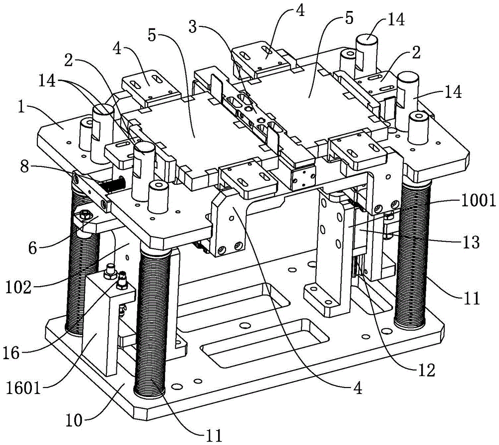
图1为本实用新型实施例所述的焊接治具的整体结构示意图;Fig. 1 is a schematic diagram of the overall structure of the welding fixture described in the embodiment of the present invention;
图2为本实用新型实施例所述的焊接治具的部分结构示意图;Fig. 2 is a partial structural schematic diagram of the welding jig described in the embodiment of the present invention;
图3为图2所示结构的其他视角下的结构示意图;Fig. 3 is a structural schematic view of the structure shown in Fig. 2 under other viewing angles;
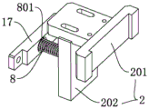
图4为本实用新型实施例所述的抵推部的结构示意图;Fig. 4 is a schematic structural diagram of the thrust part described in the embodiment of the present invention;
图5为本实用新型实施例所述的挡止部的结构示意图;Fig. 5 is a schematic structural diagram of the stopper described in the embodiment of the present invention;
图6为本实用新型实施例所述的夹爪组件的结构示意图;Fig. 6 is a schematic structural view of the jaw assembly described in the embodiment of the present invention;
图7为本实用新型实施例所述的联动机构的结构示意图;Fig. 7 is a structural schematic diagram of the linkage mechanism described in the embodiment of the present invention;
图8为本实用新型实施例所述的焊接治具工作时的结构示意图;Fig. 8 is a structural schematic diagram of the welding fixture described in the embodiment of the present invention when it is working;
附图标记说明:Explanation of reference signs:
1、基台;2、抵推部;3、挡止部;4、夹爪组件;5、电芯;6、第一连接件;7、第二连接件;8、第一弹性件;9、第二弹性件;10、底板;11、第三弹性件;12、滑轨;13、滑动座;14、承压柱;15、底座;16、检测单元;17、固定块;18、第一滑动轨;19、第一滑块;20、超声波焊接机;1. Abutment; 2. Resisting part; 3. Stopping part; 4. Gripper assembly; 5. Electric core; 6. First connector; 7. Second connector; 8. First elastic part; 9 , the second elastic member; 10, the bottom plate; 11, the third elastic member; 12, the slide rail; 13, the sliding seat; 14, the pressure column; 15, the base; 16, the detection unit; 17, the fixed block; A sliding rail; 19, the first slider; 20, an ultrasonic welding machine;
101、工位;102、第一安装板;101, station; 102, the first installation board;
201、抵推块;202、连接板;201, pushing block; 202, connecting plate;
301、极耳避让槽;301. Tab avoidance groove;
401、夹持块;402、连接块;403、安装块;4031、滑动件;401, clamping block; 402, connection block; 403, installation block; 4031, sliding part;
701、滑动槽;801、导杆;1001、第二安装板;1501、定位槽;1601、安装座。701, sliding groove; 801, guide rod; 1001, second mounting plate; 1501, positioning groove; 1601, mounting seat.
具体实施方式Detailed ways
需要说明的是,在不冲突的情况下,本实用新型中的实施例及实施例中的特征可以相互组合。It should be noted that, in the case of no conflict, the embodiments of the present invention and the features in the embodiments can be combined with each other.
在本实用新型的描述中,需要说明的是,若出现“上”、“下”、“内”、“外”等指示方位或位置关系的术语,其为基于附图所示的方位或位置关系,仅是为了便于描述本实用新型和简化描述,而不是指示或暗示所指的装置或元件必须具有特定的方位、以特定的方位构造和操作,因此不能理解为对本实用新型的限制。此外,若出现“第一”、“第二”等术语,其也仅用于描述目的,而不能理解为指示或暗示相对重要性。In the description of the present utility model, it should be noted that if there are terms such as "up", "down", "inside" and "outside" that indicate orientation or positional relationship, it is based on the orientation or position shown in the drawings. The relationship is only for the convenience of describing the utility model and simplifying the description, but does not indicate or imply that the device or element referred to must have a specific orientation, be constructed and operated in a specific orientation, and thus should not be construed as a limitation of the utility model. In addition, if terms such as "first" and "second" appear, they are used for descriptive purposes only, and cannot be understood as indicating or implying relative importance.
此外,在本实用新型的描述中,除非另有明确的限定,术语“安装”、“相连”、“连接”“连接件”应做广义理解。例如,可以是固定连接,也可以是可拆卸连接,或一体地连接;可以是机械连接,也可以是电连接;可以是直接相连,也可以通过中间媒介间接相连,可以是两个元件内部的连通。对于本领域的普通技术人员而言,可以结合具体情况理解上述术语在本实用新型中的具体含义。In addition, in the description of the present utility model, unless otherwise clearly defined, the terms "installation", "connection", "connection" and "connector" should be interpreted broadly. For example, it can be a fixed connection, a detachable connection, or an integral connection; it can be a mechanical connection or an electrical connection; it can be a direct connection or an indirect connection through an intermediary; connected. Those of ordinary skill in the art can understand the specific meanings of the above terms in the present invention in combination with specific situations.
下面将参考附图并结合实施例来详细说明本实用新型。The utility model will be described in detail below with reference to the accompanying drawings and in conjunction with the embodiments.
本实施例涉及一种焊接治具,可在两个不同方向上实现对电芯5的便捷夹持,便于实现对电芯5的定位及固定,而具有良好的使用效果。This embodiment relates to a welding jig, which can realize convenient clamping of the
在整体结构上,如图1至图8所示,本实施例的焊接治具,包括能够放置电芯5的基台1,以及设于基台1上的定位装置。In terms of overall structure, as shown in FIGS. 1 to 8 , the welding jig of this embodiment includes a
其中,定位装置包括能够沿第一方向夹紧电芯5的第一夹持机构,能够在第二方向上夹紧电芯5的第二夹持机构,以及连接在第一夹持机构和第二夹持机构之间的联动机构,联动机构用于驱使第一夹持机构和第二夹持机构同步夹紧或放开电芯5。Wherein, the positioning device includes a first clamping mechanism capable of clamping the
基于上述的整体结构,本实施例中,作为一种优选的实施方式,如图1及图2所示,基台1上设有用于放置电芯5的工位101。第一夹持机构包括相对布置于工位101的沿第一方向的两侧的抵推部2和挡止部3,第二夹持机构包括相对布置于工位101的沿第二方向的两侧的夹爪组件4。Based on the above-mentioned overall structure, in this embodiment, as a preferred implementation manner, as shown in FIG. 1 and FIG. 2 , the
并且,联动机构连接在抵推部2与两个夹爪组件4之间,使用时在联动机构的驱动下,能够使抵推部2靠近或远离挡止部3的同时,并使两个夹爪组件4相互靠近或远离。由此,可基于抵推部2和挡止部3,以及两个夹爪组件4的配合设置,使得结构设置合理,便于通过联动机构来操控第一夹持机构和第二夹持机构同步动作。Moreover, the linkage mechanism is connected between the
值得提及的是,本实施例的焊接治具一般设置有两个间隔布置的工位101,以实现两个电芯5的极耳之间的超声波焊接,具体结构中,参照图5所示,挡止部3可具体设置为位于两个工位101之间的挡止块,并在挡止块上设置有用于极耳伸出的极耳避让槽301,抵推部2则设置为位于基台1的第一方向两侧的两个,同理,第二夹持机构也设置为两个以分别对应两个工位101。It is worth mentioning that the welding jig of this embodiment is generally provided with two
同时,本实施例中每个工位101上设置有垫块,且垫块的四个角部均设有开口,以便于电芯5的取放。本实施例中的第一方向一般是指图1中所示的左右方向,也即基台1的长度方向(两个工位101的排布方向),第二方向则指基台1的宽度方向。At the same time, in this embodiment, each
并且,在整体布局上,工位101、挡止部3、抵推部2的抵推端及夹爪组件4的夹持端均优选设置在基台1顶部或上方,联动机构优选设置在基台1底部,以避免发生干涉。具体结构中,结合图4及图7所示,抵推部2包括与联动机构相连的连接板202,以及设置在连接板202上的具有上述抵推端的抵推块201,并在基台1的第一方向的两端开设有具有开口的凹槽,连接板202位于凹槽内。Moreover, in terms of the overall layout, the
夹爪组件4则包括与联动机构相连的安装块403,设于安装块403上的连接块402,以及设于连接块402上的具有上述夹持端的夹持块401。其中,连接块402位于基台1的一侧,夹持块401则朝向基台1内部延伸设置。The
此外,为提升夹持组件的移动平稳性,在基台1底部设置有沿第二方向延伸布置的第一滑动轨18,安装块403通过第一滑块19滑动与第一滑动轨18上,以使夹爪组件4能够沿第一滑动轨18滑动。In addition, in order to improve the stability of the movement of the clamping assembly, a first sliding
具体设置时,结合图3及图7所示,优选的实施形式,本实施例的联动机构包括沿第一方向滑动设于基台1底部的第一连接件6,以及设于第一连接件6上的第二连接件7,第一连接件6与抵推部2连接,第二连接件7与各夹爪组件4均通过滑动组件相连。第一连接件6沿第一方向靠近或远离挡止部3滑动时,第二连接件7能够通过两个滑动组件分别带动两个夹爪组件4相互靠近或远离。For the specific setting, as shown in Fig. 3 and Fig. 7, the preferred implementation form, the linkage mechanism of this embodiment includes the first connecting
如此设置,利于通过操作第一连接件6来实现第一夹持机构与第二夹持机构对电芯5的同步夹紧与放开。此处,第一连接件6和第二连接件7设置为板状便可,且为提升第一连接件6的滑动平稳性,可在基台1底部设置沿第一方向延伸布置的第二滑动轨,并使第一连接件6通过第二滑块滑动于第二滑动轨上。Such an arrangement facilitates synchronous clamping and releasing of the
为提升滑动组件的滑动稳定性,本实施例中,滑动组件包括设于夹爪组件4上的滑动件4031,以及设于第二连接件7上的滑动槽701,滑动件4031滑动于滑动槽701内。具体结构中,滑动槽701呈长条孔状,且沿第一方向,滑动槽701逐渐向两个夹爪组件4相互靠近的方向倾斜设置。In order to improve the sliding stability of the sliding assembly, in this embodiment, the sliding assembly includes a sliding
具体而言,本实施例的滑动件4031设置在夹爪组件4的安装块403的底部,且沿第一方向,并在基台1的左端至右端的视角下,两个滑动槽701在整体上呈“八”字形,以可通过第一连接件6拉动抵推部2远离挡止部3时,滑动槽701迫使两个滑动件4031相互远离,也即第一夹持机构解除对电芯5夹持的同时,第二夹持机构也解除对电芯5的夹持。Specifically, the sliding
此外,本实施例中,作为一种优选的实施方式,联动机构与基台1之间设有弹性部,第一夹持机构和第二夹持机构放开电芯5时,能够通过联动机构压缩弹性部,且弹性部释能时,能够通过联动机构驱使第一夹持机构和第二夹持机构夹紧电芯5。由此,可在没有外力操控联动机构的情况下,使得第一夹持机构和第二夹持机构自动夹紧电芯5,实现电芯5的自动定位。In addition, in this embodiment, as a preferred implementation mode, an elastic part is provided between the linkage mechanism and the
如图2、图3、图4及图6所示,优选的实施形式,上述弹性部包括设于抵推部2与基台1之间的第一弹性件8,以及设于两个夹爪组件4之间的第二弹性件9,第一弹性件8通过抵推部2与联动机构相连,第二弹性件9通过两个夹爪组件4与联动机构相连。此处第一弹性件8与第二弹性件9的配合设置,结构简单,且易于布置及实现。As shown in Fig. 2, Fig. 3, Fig. 4 and Fig. 6, the preferred implementation form, the above-mentioned elastic part includes the first
此处的第一弹性件8和第二弹性件9采用常规的弹簧产品便可,以使结构简单,成本低廉。具体设置时,在凹槽的开口处设有固定块17,在第一弹性件8设置在固定块17与连接板202之间,且为实现第一弹性件8的稳定使用,可在固定块17上设置导杆801,并在连接板202设置供导杆801穿经的通孔,第一弹性件8套设在导杆801上,且第一弹性件8的两端分别抵接在固定块17和连接板202上。而第二弹性件9则具体设置在两个夹爪组件4的安装块403上。Here, the first
另外,本实施例中,作为一种优选的实施方式,如图1至图3所示,沿基台1的高度方向,基台1上下可调设置,以可在将焊接治具送至焊接位置时将基台1高度调低,避免与焊接装置发生碰撞。In addition, in this embodiment, as a preferred implementation, as shown in Figures 1 to 3, along the height direction of the
优选的实施形式,本实施例中,基台1的下方设有带有支撑柱的底板10,基台1滑动设于支撑柱上,并于基台1和底板10之间设有第三弹性件11。以此,可利于实现基台1的上下位置弹性调节,提升基台1高度变化的便捷性,且此处的第三弹性件11采用常规的弹簧产品便可。The preferred form of implementation, in this embodiment, the bottom of the
本实施例中,为提升基台1上下位置弹性调节过程的稳定性及可靠性,基台1上设有沿基台1高度方向延伸布置的滑轨12,底板10通过滑动座13滑动于滑轨12上。具体来讲,滑轨12布置在基台1底部的沿基台1高度方向延伸设置的第一安装板102上,滑动座13布置在底板10顶部的沿基台1高度方向延伸布置的第二安装板1001上,以使结构简单,布置合理。In this embodiment, in order to improve the stability and reliability of the elastic adjustment process of the upper and lower positions of the
同时,为便于基台1承受外部下压力,本实施例中,基台1的顶部设有用于承接外部下压机构下压操作的承压柱14。具体结构中,该承压柱14的数量与布置形式,可根据实际的承压需求及稳定性需求进行相应的设定与调整,例如具体可设置为间隔布置的四个,且四个承压柱14呈矩形分布。At the same time, in order to facilitate the
本实施例中,仍如图1所示,优选的实施形式,底板10上设有用于检测基台1与底板10的间距的检测单元16,以便于检测基台1是否下移至安全工作高度。该检测单元16可采用常规的测量距离的传感器,例如具体可为超声波测距传感器、激光测距传感器或红外线测距传感器等。In this embodiment, as shown in FIG. 1, in a preferred implementation form, the
同时,为便于检测单元16布置,可在底板10上设置用于安装检测单元16的安装座1601,且该安装座1601的布置位置根据整体结构的布置需求进行设定与调整便可。本实施例中,为实现焊接治具的定位放置,底板10上设有用于定位基台1的放置位置的定位槽1501,该定位槽1501的具体结构设计可根据实际的定位需求进行相应的设定与调整,例如具体可设置为三角形的凹槽。At the same time, in order to facilitate the arrangement of the
值得提及的是,在实际应用时,如图8所示,本实施例的焊接治具一般设置为两组,与两组超声波焊接机20对应使用,以便于取得较好的作业效率,且为便于操作,两组焊接治具均设置在底座15上,上述定位槽1501则优选设置在底座15上,以实现两组焊接治具的定位。It is worth mentioning that, in actual application, as shown in Figure 8, the welding jigs of this embodiment are generally set in two groups, which are used correspondingly with two groups of
本实施例的焊接治具在使用时,首先通过外部叉式载具同时操作两个第一连接件6,使得两个第一连接件6同步远离挡止部,此时,两个第二夹持机构在对应的第二连接件7的驱动下,也同步解除夹持动作,随后将两个电芯5分别放置在两个工位101,并撤去叉式载具,两个第一连接件6在第一弹性件8的作用下,朝向挡止部3滑动,此时,两个第二夹持机构在对应的第二弹性件9的作用下夹持电芯5,直至将电芯5在第一方向及第二方向上夹紧固定。When the welding jig of this embodiment is in use, the two
然后,启动下压机构,下压机构通过承压柱14下压基台1,使基台1下降至适宜高度,再将焊接治具放置至焊接位置,也即对应超声波焊接机20放置,放置过程通过定位槽1501进行定位便可,随后对电芯5实施焊接作业,焊接作业完毕后,移出焊接治具,卸去下压机构的下压操作,并通过叉式载具解除第一夹持机构与第二夹持机构对电芯5的夹持,便可取出电芯5,由此完成焊接作业。Then, start the pressing mechanism, and the pressing mechanism presses down the
本实施例的焊接治具,通过第一夹持机构和第二夹持机构的配合,可在两个不同方向上对电芯5进行夹持,利于实现对电芯5的定位及固定,且联动机构的设置,还可实现对第一夹持机构和第二夹持机构的同步操作,提升操作便捷性,而可具有良好的使用效果。The welding jig of this embodiment can clamp the
以上所述仅为本实用新型的较佳实施例而已,并不用以限制本实用新型,凡在本实用新型的精神和原则之内,所作的任何修改、等同替换、改进等,均应包含在本实用新型的保护范围之内。The above descriptions are only preferred embodiments of the present utility model, and are not intended to limit the present utility model. Any modifications, equivalent replacements, improvements, etc. made within the spirit and principles of the present utility model shall be included in the Within the protection scope of the present utility model.
Claims (10)
Priority Applications (1)
| Application Number | Priority Date | Filing Date | Title |
|---|---|---|---|
| CN202223410858.4U CN218946778U (en) | 2022-12-19 | 2022-12-19 | Welding jig |
Applications Claiming Priority (1)
| Application Number | Priority Date | Filing Date | Title |
|---|---|---|---|
| CN202223410858.4U CN218946778U (en) | 2022-12-19 | 2022-12-19 | Welding jig |
Publications (1)
| Publication Number | Publication Date |
|---|---|
| CN218946778U true CN218946778U (en) | 2023-05-02 |
Family
ID=86106063
Family Applications (1)
| Application Number | Title | Priority Date | Filing Date |
|---|---|---|---|
| CN202223410858.4U Active CN218946778U (en) | 2022-12-19 | 2022-12-19 | Welding jig |
Country Status (1)
| Country | Link |
|---|---|
| CN (1) | CN218946778U (en) |
-
2022
- 2022-12-19 CN CN202223410858.4U patent/CN218946778U/en active Active
Similar Documents
| Publication | Publication Date | Title |
|---|---|---|
| CN209256743U (en) | A cell centering clamping mechanism | |
| WO2025236579A1 (en) | Bending apparatus and floating bending device thereof | |
| CN118544003A (en) | Fixtures and laser processing equipment | |
| CN110280899A (en) | A kind of clamping component and clamping assemblies | |
| CN110315262A (en) | A kind of rectangular cell module busbar connector clamping tool | |
| CN211180238U (en) | Nail pulling detection device and nail pulling system | |
| CN111730261A (en) | A kind of battery negative lead terminal welding fixture | |
| CN110767930B (en) | Battery clamp and battery assembly method | |
| CN220348183U (en) | Cell clamp and cell module stacking device | |
| CN111993339A (en) | Pin crimping device | |
| CN219597931U (en) | Top cap pin plastic mechanism | |
| CN219521106U (en) | Battery case tooling | |
| CN218080931U (en) | Electricity core positioning and clamping device | |
| CN117506275A (en) | Fixture for blade battery case welding | |
| CN217433383U (en) | A flexible high-precision positioning fixture and automatic laser welding equipment | |
| CN115971752A (en) | Aligning device of lithium cell PACK equipment | |
| CN211401946U (en) | Lithium battery detection device | |
| CN211565017U (en) | Wire rod loading attachment is used in equipment of Type-C earphone link iron-clad | |
| CN222449005U (en) | Workpiece positioning device | |
| CN210588946U (en) | Fast-assembling anchor clamps | |
| CN210848919U (en) | A pressure head of a clamping assembly | |
| CN211866918U (en) | Welding equipment | |
| CN219106223U (en) | Cell Block Stacking Device | |
| CN224005152U (en) | Blocking detection and rotation current device for motor | |
| CN216177950U (en) | Aligning device of lithium cell PACK equipment |
Legal Events
| Date | Code | Title | Description |
|---|---|---|---|
| GR01 | Patent grant | ||
| GR01 | Patent grant |