CN218927284U - Grinding machine for machining - Google Patents
Grinding machine for machining Download PDFInfo
- Publication number
- CN218927284U CN218927284U CN202223055119.8U CN202223055119U CN218927284U CN 218927284 U CN218927284 U CN 218927284U CN 202223055119 U CN202223055119 U CN 202223055119U CN 218927284 U CN218927284 U CN 218927284U
- Authority
- CN
- China
- Prior art keywords
- box body
- grinding
- grinding machine
- water
- filter plate
- Prior art date
- Legal status (The legal status is an assumption and is not a legal conclusion. Google has not performed a legal analysis and makes no representation as to the accuracy of the status listed.)
- Active
Links
- 238000003754 machining Methods 0.000 title claims abstract description 21
- 230000007246 mechanism Effects 0.000 claims abstract description 46
- XLYOFNOQVPJJNP-UHFFFAOYSA-N water Substances O XLYOFNOQVPJJNP-UHFFFAOYSA-N 0.000 claims abstract description 39
- 238000005498 polishing Methods 0.000 claims abstract description 11
- 230000005540 biological transmission Effects 0.000 claims abstract description 10
- 238000011010 flushing procedure Methods 0.000 claims abstract description 9
- 238000005507 spraying Methods 0.000 claims abstract description 3
- 239000011521 glass Substances 0.000 claims description 9
- 239000007921 spray Substances 0.000 claims description 6
- 230000005012 migration Effects 0.000 claims description 2
- 238000013508 migration Methods 0.000 claims description 2
- 238000007517 polishing process Methods 0.000 abstract description 4
- 230000009286 beneficial effect Effects 0.000 abstract description 2
- 238000004140 cleaning Methods 0.000 abstract description 2
- 239000000463 material Substances 0.000 description 3
- 239000012535 impurity Substances 0.000 description 2
- 238000009434 installation Methods 0.000 description 2
- 238000012545 processing Methods 0.000 description 2
- 229910000760 Hardened steel Inorganic materials 0.000 description 1
- 239000003082 abrasive agent Substances 0.000 description 1
- 229910045601 alloy Inorganic materials 0.000 description 1
- 239000000956 alloy Substances 0.000 description 1
- 238000004891 communication Methods 0.000 description 1
- 238000010276 construction Methods 0.000 description 1
- 238000010586 diagram Methods 0.000 description 1
- 239000000284 extract Substances 0.000 description 1
- 238000001914 filtration Methods 0.000 description 1
- 239000010438 granite Substances 0.000 description 1
- 238000012986 modification Methods 0.000 description 1
- 230000004048 modification Effects 0.000 description 1
- 230000003746 surface roughness Effects 0.000 description 1
- 238000005406 washing Methods 0.000 description 1
- 239000002699 waste material Substances 0.000 description 1
Images


Classifications
-
- Y—GENERAL TAGGING OF NEW TECHNOLOGICAL DEVELOPMENTS; GENERAL TAGGING OF CROSS-SECTIONAL TECHNOLOGIES SPANNING OVER SEVERAL SECTIONS OF THE IPC; TECHNICAL SUBJECTS COVERED BY FORMER USPC CROSS-REFERENCE ART COLLECTIONS [XRACs] AND DIGESTS
- Y02—TECHNOLOGIES OR APPLICATIONS FOR MITIGATION OR ADAPTATION AGAINST CLIMATE CHANGE
- Y02P—CLIMATE CHANGE MITIGATION TECHNOLOGIES IN THE PRODUCTION OR PROCESSING OF GOODS
- Y02P70/00—Climate change mitigation technologies in the production process for final industrial or consumer products
- Y02P70/10—Greenhouse gas [GHG] capture, material saving, heat recovery or other energy efficient measures, e.g. motor control, characterised by manufacturing processes, e.g. for rolling metal or metal working
Landscapes
- Grinding-Machine Dressing And Accessory Apparatuses (AREA)
Abstract
The utility model discloses a grinding machine for machining, which comprises a grinding mechanism for grinding workpieces, a transmission mechanism arranged below the grinding mechanism and used for horizontal movement adjustment, a box body mechanism arranged outside the transmission mechanism and used for providing an operation space, and a flushing mechanism arranged behind the box body mechanism and used for spraying water for cleaning, wherein the box body mechanism comprises a main box body, two sliding rails are symmetrically arranged on the inner walls of two sides of the main box body, a filter plate is arranged between the sliding rails, a first handle is arranged in front of the filter plate, and a box door is arranged in front of the main box body. The beneficial effects are that: the water in the water tank is extracted to wash the polishing workpiece, so that scraps generated in the polishing process are cleaned, and the working efficiency is improved; the water resource is recycled by extracting the filtered water, so that the resource is saved; through the setting of pull formula filter, can clean the sweeps that produces fast, use manpower sparingly.
Description
Technical Field
The utility model relates to the technical field of machining, in particular to a grinding machine for machining.
Background
Grinding machines are machine tools for grinding the surface of a workpiece by using grinding tools, most of the grinding machines are grinding machines by using grinding wheels rotating at high speed, and a few of the grinding machines are grinding machines by using other grinding tools such as oilstones, abrasive belts and the like and free abrasive materials, such as honing machines, superfinishing machines, abrasive belt grinding machines, polishing machines and the like, wherein the grinding machines can be used for processing materials with higher hardness, such as hardened steel, hard alloy and the like, and also can be used for processing brittle materials, such as glass and granite, and the grinding machines can be used for grinding with high precision and small surface roughness, and also can be used for grinding with high efficiency, such as powerful grinding and the like.
Through retrieving current patent number for CN202022420760.1, a grinding machine for comprehensive machining, including workstation, supporting shoe and limiting plate, T shape spout has been seted up to the workstation trailing flank, and the workstation left and right sides face all is provided with first link, and first link left side is provided with servo motor simultaneously, servo motor is connected with first motor shaft, and first motor shaft right-hand member is provided with the threaded rod, and the threaded rod runs through first link, the supporting shoe sets up at the workstation trailing side, and the supporting shoe left surface has been seted up threaded hole, and the threaded hole runs through the supporting shoe right flank simultaneously, the threaded hole is run through to the threaded rod right-hand member, the supporting shoe leading flank is provided with T shape slider, and T shape slider sets up inside T shape spout, the supporting shoe upside is provided with the pneumatic cylinder, and the inboard is provided with the piston rod on the pneumatic cylinder, and the piston rod upper end is provided with the second link simultaneously.
The above-mentioned patent does not set up the setting of collecting the waste material that polishes down, still needs the manual work to clear up after leading to polishing to accomplish, extravagant manpower, work efficiency is lower.
Disclosure of Invention
The present utility model has been made to solve the above-mentioned problems, and an object of the present utility model is to provide a grinding machine for machining.
The utility model realizes the above purpose through the following technical scheme:
the utility model provides a grinding machine for machining, including the grinding machanism that is used for polishing the work piece with the drive mechanism that is used for the horizontal migration to adjust that the grinding machanism below set up still includes the box mechanism that is used for providing the operation space of drive mechanism outside installation with the flushing mechanism that is used for the water spray to clear up of box mechanism installation at the back, box mechanism includes the main box, two slide rails are installed to symmetry on the inner wall of main box both sides, install the filter between the slide rails, install first handle in front of the filter, install the chamber door in front of the main box, install the glass window on the chamber door, glass window one side is provided with the second handle, flushing mechanism includes the water tank, install the connecting pipe at the back of water tank, the connecting pipe is kept away from the one end of water tank is installed the water pump, the shower nozzle is installed in front to the water pump.
Preferably: the transmission mechanism comprises first linear guide rails, two first linear guide rails are symmetrically arranged, two first linear motors are symmetrically arranged on each first linear guide rail, a second linear guide rail is arranged on each first linear motor, two second linear motors are symmetrically arranged on each second linear guide rail, a working plate is arranged on each second linear motor, four electric push rods are uniformly arranged on the working plate, and an anti-slip base plate is arranged at the telescopic end of each electric push rod.
Preferably: the polishing mechanism comprises a hydraulic cylinder, a rotating motor is arranged below the hydraulic cylinder, and a grinding disc is arranged at the output end of the rotating motor.
Preferably: the filter plate is connected with the sliding rail in a sliding way, and the first handle is welded with the filter plate.
Preferably: the main box body is rectangular.
Preferably: the anti-skid backing plate is made of rubber, and is connected with the electric push rod through bolts.
Compared with the prior art, the utility model has the following beneficial effects:
1. the water in the water tank is extracted to wash the polishing workpiece, so that scraps generated in the polishing process are cleaned, and the working efficiency is improved;
2. the water resource is recycled by extracting the filtered water, so that the resource is saved;
3. through the setting of pull formula filter, can clean the sweeps that produces fast, use manpower sparingly.
Drawings
In order to more clearly illustrate the embodiments of the utility model or the technical solutions of the prior art, the drawings that are necessary for the description of the embodiments or the prior art will be briefly described, it being obvious that the drawings in the following description are only some embodiments of the utility model and that other drawings can be obtained according to these drawings without inventive faculty for a person skilled in the art.
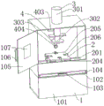
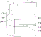
FIG. 1 is a view showing the construction of an external appearance of a grinding machine for machining according to the present utility model;
FIG. 2 is a schematic diagram of a housing mechanism of a grinding machine for machining according to the present utility model;
FIG. 3 is a schematic cross-sectional elevation view of a housing mechanism of a grinding machine for machining according to the present utility model;
FIG. 4 is a schematic view of a transmission mechanism of a grinding machine for machining according to the present utility model;
FIG. 5 is a schematic view of a grinding mechanism of a grinding machine for machining according to the present utility model;
fig. 6 is a schematic view of a flushing mechanism of a grinding machine for machining according to the present utility model.
The reference numerals are explained as follows:
1. a box mechanism; 101. a main case; 102. a filter plate; 103. a first handle; 104. a slide rail; 105. a door; 106. a second handle; 107. a glazing; 2. a transmission mechanism; 201. a first linear guide rail; 202. a first linear motor; 203. a second linear guide rail; 204. a second linear motor; 205. a work plate; 206. an electric push rod; 207. an anti-slip backing plate; 3. a polishing mechanism; 301. a hydraulic cylinder; 302. a rotating electric machine; 303. grinding disc; 4. a flushing mechanism; 401. a water tank; 402. a connecting pipe; 403. a water pump; 404. a spray head.
Detailed Description
In the description of the present utility model, it should be understood that the terms "center", "longitudinal", "lateral", "upper", "lower", "front", "rear", "left", "right", "vertical", "horizontal", "top", "bottom", "inner", "outer", etc. indicate orientations or positional relationships based on the orientations or positional relationships shown in the drawings, are merely for convenience in describing the present utility model and simplifying the description, and do not indicate or imply that the devices or elements referred to must have a specific orientation, be configured and operated in a specific orientation, and thus should not be construed as limiting the present utility model. Furthermore, the terms "first," "second," and the like, are used for descriptive purposes only and are not to be construed as indicating or implying a relative importance or implicitly indicating the number of technical features indicated. Thus, a feature defining "a first", "a second", etc. may explicitly or implicitly include one or more such feature. In the description of the present utility model, unless otherwise indicated, the meaning of "a plurality" is two or more.
In the description of the present utility model, it should be noted that, unless explicitly specified and limited otherwise, the terms "mounted," "connected," and "connected" are to be construed broadly, and may be either fixedly connected, detachably connected, or integrally connected, for example; can be mechanically or electrically connected; can be directly connected or indirectly connected through an intermediate medium, and can be communication between two elements. The specific meaning of the above terms in the present utility model can be understood by those of ordinary skill in the art in a specific case.
The utility model is further described below with reference to the accompanying drawings:
as shown in fig. 1 to 6, a grinding machine for machining comprises a grinding mechanism 3 for grinding a workpiece, a transmission mechanism 2 arranged below the grinding mechanism 3 and used for horizontal movement adjustment, a box body mechanism 1 arranged outside the transmission mechanism 2 and used for providing a working space, and a flushing mechanism 4 arranged behind the box body mechanism 1 and used for spraying water for cleaning.
In this embodiment: the box body mechanism 1 comprises a main box body 101, two sliding rails 104 are symmetrically arranged on the inner walls of two sides of the main box body 101, a filter plate 102 is arranged between the sliding rails 104, a first handle 103 is arranged in front of the filter plate 102, a box door 105 is arranged in front of the main box body 101, a glass window 107 is arranged on the box door 105, a second handle 106 is arranged on one side of the glass window 107, the filter plate 102 and the sliding rails 104 are in sliding connection, the first handle 103 and the filter plate 102 are welded together, the main box body 101 is rectangular, the filter plate 102 is driven to move along the sliding rails 104 by pulling the first handle 103, the filter plate 102 is used for filtering impurities in water, and the glass window 107 is used for observing the condition inside the main box body 101.
In this embodiment: the transmission mechanism 2 comprises two first linear guide rails 201, two first linear motors 202 are symmetrically arranged on each first linear guide rail 201, a second linear guide rail 203 is arranged on each first linear motor 202, two second linear motors 204 are symmetrically arranged on each second linear guide rail 203, a working plate 205 is arranged on each second linear motor 204, four electric push rods 206 are uniformly arranged on each working plate 205, anti-slip base plates 207 are arranged at telescopic ends of the electric push rods 206, the anti-slip base plates 207 are made of rubber materials, the anti-slip base plates 207 are in bolted connection with the electric push rods 206, the first linear motors 202 drive the second linear guide rails 203 to move along the first linear guide rails 201, the second linear motors 204 drive the working plates 205 to move along the second linear guide rails 203, and the electric push rods 206 push the anti-slip base plates 207 to move.
In this embodiment: the polishing mechanism 3 comprises a hydraulic cylinder 301, a rotating motor 302 is arranged below the hydraulic cylinder 301, a grinding disc 303 is arranged at the output end of the rotating motor 302, the hydraulic cylinder 301 pushes the rotating motor 302 and the grinding disc 303 to move, and the rotating motor 302 drives the grinding disc 303 to rotate.
In this embodiment: the flushing mechanism 4 comprises a water tank 401, a connecting pipe 402 is arranged at the rear of the water tank 401, a water pump 403 is arranged at one end, far away from the water tank 401, of the connecting pipe 402, a spray head 404 is arranged in front of the water pump 403, and the water pump 403 pumps water in the water tank 401 through the connecting pipe 402 and is sprayed out of the spray head 404.
Working principle: the work piece is placed on the operation board 205 in the main box 101, the electric push rod 206 pushes the anti-slip backing plate 207 to clamp the work piece firmly from four directions, the work piece is prevented from sliding in the polishing process, then the hydraulic cylinder 301 pushes the rotating motor 302 and the grinding disc 303 to move to a proper position, the rotating motor 302 drives the grinding disc 303 to rotate at a high speed, then the second handle 106 is held to close the box door 105 on the main box 101, then the first linear motor 202 drives the second linear guide rail 203 to move along the first linear guide rail 201, the second linear motor 204 drives the operation board 205 to move along the second linear guide rail 203, the work piece is polished through the grinding disc 303 rotating at a high speed by the cooperation of the first linear motor 202 and the second linear motor 204, the water pump 403 extracts water in the water tank 401 through the connecting pipe 402 in the polishing process, then the water is sprayed out by the spray head 404, the work piece which is polished is washed, the water after washing flows into the water tank 401 again through the filter plate 102, the glass window 107 can observe the working condition in the main box 101 at any time, and finally when the impurity on the filter plate 102 is accumulated too much, the first handle 103 only needs to drive the first handle 102 to move out of the filter plate 104 to clean the slide rail 101.
The foregoing has shown and described the basic principles, principal features and advantages of the utility model. It will be understood by those skilled in the art that the present utility model is not limited to the embodiments described above, and that the above embodiments and descriptions are merely illustrative of the principles of the present utility model, and various changes and modifications may be made without departing from the spirit and scope of the utility model, which is defined in the appended claims.
Claims (6)
1. The utility model provides a grinding machine for machining, includes grinding machanism (3) that are used for polishing the work piece and drive mechanism (2) that are used for horizontal migration to adjust that are arranged in grinding machanism (3) below, its characterized in that: the device also comprises a box body mechanism (1) which is arranged outside the transmission mechanism (2) and used for providing an operation space, and a flushing mechanism (4) which is arranged behind the box body mechanism (1) and used for spraying water to clean;
the box mechanism (1) comprises a main box body (101), two sliding rails (104) are symmetrically arranged on the inner walls of two sides of the main box body (101), a filter plate (102) is arranged between the sliding rails (104), a first handle (103) is arranged in front of the filter plate (102), a box door (105) is arranged in front of the main box body (101), a glass window (107) is arranged on the box door (105), and a second handle (106) is arranged on one side of the glass window (107);
the flushing mechanism (4) comprises a water tank (401), a connecting pipe (402) is arranged behind the water tank (401), a water pump (403) is arranged at one end, far away from the water tank (401), of the connecting pipe (402), and a spray head (404) is arranged in front of the water pump (403).
2. A grinding machine for machining according to claim 1, characterized in that: the transmission mechanism (2) comprises first linear guide rails (201), two first linear guide rails (201) are symmetrically arranged, two first linear motors (202) are symmetrically arranged on each first linear guide rail (201), two second linear guide rails (203) are arranged on each first linear motor (202), two second linear motors (204) are symmetrically arranged on each second linear guide rail (203), an operation plate (205) is arranged on each second linear motor (204), four electric push rods (206) are uniformly arranged on each operation plate (205), and anti-slip base plates (207) are arranged at telescopic ends of the electric push rods (206).
3. A grinding machine for machining according to claim 1, characterized in that: the polishing mechanism (3) comprises a hydraulic cylinder (301), a rotating motor (302) is installed below the hydraulic cylinder (301), and a polishing disc (303) is installed at the output end of the rotating motor (302).
4. A grinding machine for machining according to claim 1, characterized in that: the filter plate (102) is in sliding connection with the sliding rail (104), and the first handle (103) and the filter plate (102) are welded together.
5. A grinding machine for machining according to claim 1, characterized in that: the main box body (101) is rectangular.
6. A grinding machine for machining according to claim 2, characterized in that: the anti-skid backing plate (207) is made of rubber, and the anti-skid backing plate (207) is connected with the electric push rod (206) through bolts.
Priority Applications (1)
| Application Number | Priority Date | Filing Date | Title |
|---|---|---|---|
| CN202223055119.8U CN218927284U (en) | 2022-11-17 | 2022-11-17 | Grinding machine for machining |
Applications Claiming Priority (1)
| Application Number | Priority Date | Filing Date | Title |
|---|---|---|---|
| CN202223055119.8U CN218927284U (en) | 2022-11-17 | 2022-11-17 | Grinding machine for machining |
Publications (1)
| Publication Number | Publication Date |
|---|---|
| CN218927284U true CN218927284U (en) | 2023-04-28 |
Family
ID=86067943
Family Applications (1)
| Application Number | Title | Priority Date | Filing Date |
|---|---|---|---|
| CN202223055119.8U Active CN218927284U (en) | 2022-11-17 | 2022-11-17 | Grinding machine for machining |
Country Status (1)
| Country | Link |
|---|---|
| CN (1) | CN218927284U (en) |
-
2022
- 2022-11-17 CN CN202223055119.8U patent/CN218927284U/en active Active
Similar Documents
| Publication | Publication Date | Title |
|---|---|---|
| CN217453235U (en) | Numerical control cylindrical grinder is used in auto-parts axostylus axostyle processing | |
| CN214722902U (en) | Faucet water outlet grinding equipment for production and processing | |
| CN215240214U (en) | Grinding disc surface cleaning equipment for grinding machine | |
| CN115351611A (en) | Polishing equipment based on tungsten steel coating forming cutter processing | |
| CN219005732U (en) | Anti-blocking grinding machine | |
| CN113414650A (en) | Fastener processing equipment | |
| CN219189852U (en) | Rust removal device for die steel processing | |
| CN218254137U (en) | Cutting waste chip recycling auxiliary structure | |
| CN214817525U (en) | Environment-friendly grinding machine for machining | |
| CN213351893U (en) | Grinding device for machining with dust collection function | |
| CN210849157U (en) | Metal product hole machining and grinding device | |
| CN220240651U (en) | Turning and polishing integrated machine | |
| CN216939779U (en) | Cooling device for building material processing | |
| CN219310934U (en) | From ceramic polisher of taking safeguard function | |
| CN220944538U (en) | Hardware processing blank surface cleaning device | |
| CN223889751U (en) | Grinding machine cleaning device for waste parts | |
| CN222404907U (en) | A stainless steel grinding machine with cleaning function | |
| CN219817250U (en) | Orifice deburring device | |
| CN221675151U (en) | A cleaning device with a convenient fixing structure | |
| CN216504182U (en) | Multi-station grinding machine | |
| CN221158706U (en) | Bench drilling machine convenient to retrieve sweeps | |
| CN217255141U (en) | Cleaning device is used in ball tooth production | |
| CN219337091U (en) | Large water mill convenient for removing mud scale for machining mechanical parts | |
| CN224088788U (en) | Grinding machine | |
| CN219704662U (en) | Station circulation working equipment with good protection effect |
Legal Events
| Date | Code | Title | Description |
|---|---|---|---|
| GR01 | Patent grant | ||
| GR01 | Patent grant |