CN218904376U - CNC adds clamping apparatus - Google Patents
CNC adds clamping apparatus Download PDFInfo
- Publication number
- CN218904376U CN218904376U CN202320182467.7U CN202320182467U CN218904376U CN 218904376 U CN218904376 U CN 218904376U CN 202320182467 U CN202320182467 U CN 202320182467U CN 218904376 U CN218904376 U CN 218904376U
- Authority
- CN
- China
- Prior art keywords
- groove
- fixing
- mounting hole
- fixing hole
- cnc
- Prior art date
- Legal status (The legal status is an assumption and is not a legal conclusion. Google has not performed a legal analysis and makes no representation as to the accuracy of the status listed.)
- Active
Links
- 238000003754 machining Methods 0.000 claims abstract description 20
- 238000009434 installation Methods 0.000 claims description 3
- 239000000463 material Substances 0.000 abstract description 9
- 230000000694 effects Effects 0.000 abstract description 4
- 238000004519 manufacturing process Methods 0.000 description 4
- 238000000034 method Methods 0.000 description 4
- 238000005516 engineering process Methods 0.000 description 3
- 238000012986 modification Methods 0.000 description 2
- 230000004048 modification Effects 0.000 description 2
- 230000006978 adaptation Effects 0.000 description 1
- 230000009286 beneficial effect Effects 0.000 description 1
- 239000002131 composite material Substances 0.000 description 1
- 238000010586 diagram Methods 0.000 description 1
- 230000007613 environmental effect Effects 0.000 description 1
- 238000007689 inspection Methods 0.000 description 1
- 230000000149 penetrating effect Effects 0.000 description 1
- 238000003466 welding Methods 0.000 description 1
Images
Landscapes
- Jigs For Machine Tools (AREA)
Abstract
The utility model provides a CNC adds fixed fixture, relates to anchor clamps technical field, including location structure, fixed base and connection base, location structure's an end and fixed base are connected, location structure's an end and connection base are kept away from to the fixed base are connected, location structure is including locating piece and spacing portion, the lower surface of locating piece and fixed base's last fixed surface are connected, spacing position is located in the locating piece, the spacing groove has been seted up on the spacing portion. The CNC machining fixing clamp has the advantages of good fixing effect, high working efficiency, simple structure, material cost saving, convenience in use and the like.
Description
Technical Field
The utility model relates to the technical field of clamps, in particular to a CNC machining fixing clamp.
Background
The fixture is a technological device for fast fastening workpiece during machining to maintain proper relative position of machine tool, cutter and workpiece. Driven by the development of machine tool technology to high speed, high efficiency, precision, composite, intelligent and environmental protection, clamp technology is developing to high precision, high efficiency, module, combination, general and economic directions. The fixture is also called a fixture, and in a broad sense, any process in the process, a device for rapidly, conveniently and safely mounting a workpiece can be called a fixture, such as a welding fixture, an inspection fixture, an assembly fixture, a machine tool fixture, a fixing fixture, etc., and the fixture has a direct influence on the production efficiency and the product quality. Particularly in CNC machining (CNC, computerized Numerical Control Machine, computer numerical control machine tool, abbreviated as numerical control machine tool), it is often necessary to clamp and fix a workpiece to be machined by a fixing jig. The surface of a plurality of different directions of work piece all need carry out fixed processing, and the processing mode that current is commonly used is fixed the work piece on mounting fixture, and the cutter is processed a face earlier, then is dismantled the product again by the manual work and is traded the face repositioning, then processes other faces again, and this kind of processing mode needs many times location, and manual operation is comparatively laborsaving moreover, and then reduces the machining efficiency of work piece.
Disclosure of Invention
The utility model aims to provide a CNC machining fixing clamp, which aims to solve the technical problems, and has the advantages of good fixing effect, high working efficiency, simple structure, material cost saving, convenience in use and the like.
In order to achieve the above purpose, the present utility model is realized by the following technical scheme:
the utility model provides a CNC adds fixed fixture, including location structure, fixed base and connection base, location structure's an end and fixed base are connected, location structure's an end and connection base are kept away from to the fixed base are connected, location structure is including locating piece and spacing portion, the lower surface of locating piece and fixed base's last fixed surface are connected, spacing position is located in the locating piece, the spacing groove has been seted up on the spacing portion. The limiting groove is used for placing a workpiece to be processed instead of machining.
Further, the positioning structure further comprises fixing portions, and the fixing portions are symmetrically arranged on two sides of the limiting groove.
Further, a first fixing hole and a second fixing hole are formed in the fixing portion, the first fixing hole is located on one side of the limiting portion, the second fixing hole is located on one side, away from the first fixing hole, of the limiting portion, and the first fixing hole and the second fixing hole are communicated with the limiting groove.
Further, the positioning block is further provided with a concave part and an empty groove, the concave part is located at one side of the first fixing hole, the empty groove is located below the second fixing hole, and the empty groove is communicated with the limiting groove. The arrangement of the concave part and the empty groove can reduce the manufacturing materials of the positioning block and save the material cost.
Further, the fixing base is provided with mounting portions which are symmetrically arranged on two sides of the positioning block and are located at two end portions of the fixing base.
Further, be equipped with mounting hole, lower mounting hole and hollow joint platform in the installation department, hollow joint platform is located between mounting hole and the lower mounting hole, the diameter of going up the mounting hole is greater than the diameter of mounting hole down, go up all the intercommunication setting between mounting hole, lower mounting hole and the hollow joint platform.
Further, a connecting groove is further formed in the positioning block, and the connecting groove is correspondingly communicated with the limiting groove.
Further, the connecting base is circular, and an extending groove is formed in the connecting base and is correspondingly communicated with the connecting groove.
The CNC machining fixing clamp has the following beneficial effects:
1. the CNC machining fixing clamp has the advantages that the fixing effect is good, after the workpiece to be machined is placed in the limiting groove, the limiting groove can be used for preliminarily limiting and fixing the workpiece, then the workpiece can be fixed by adopting the fastener to pass through the first fixing hole, the workpiece and the second fixing hole, the fixing effect is good, and the use is convenient;
2. the CNC machining fixture is high in working efficiency, the connecting base is inserted into the central groove of the CNC index plate to be matched with the CNC index plate, and then the fixing piece sequentially penetrates through the upper mounting hole, the hollow clamping table and the lower mounting hole of the fixing base to be fixedly connected with the locking groove of the CNC index plate, so that the fixture can be firmly connected with the CNC index plate, and a workpiece can be subjected to multi-surface machining under the drive of the CNC index plate, so that the fixture is high in working efficiency and strong in practicability;
3. the CNC machining fixing clamp mainly comprises a positioning structure, a fixing base and a connecting base, and is few in component parts and simple in structure;
4. the CNC processing fixing clamp saves material cost, the positioning block is also provided with the concave part and the empty groove, the concave part is positioned at one side of the first fixing hole, the empty groove is positioned below the second fixing hole, and the empty groove is communicated with the limiting groove. The arrangement of the concave part and the empty groove can reduce the manufacturing materials of the positioning block and save the material cost.
Drawings
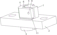
FIG. 1 is a schematic diagram of the overall structure of a CNC machining fixture of the present utility model;
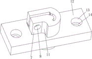
FIG. 2 is a schematic view of the workpiece plate shown in FIG. 1;
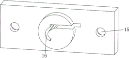
fig. 3 is a schematic structural view of the station base shown in fig. 1.
Description of the embodiments
In order to make the technical solution of the present utility model better understood by those skilled in the art, the following further details of the present utility model will be described with reference to examples and drawings.
It will be understood that when an element is referred to as being "fixed to" another element, it can be directly on the other element or intervening elements may also be present; when an element is referred to as being "connected" to another element, it can be directly connected to the other element or intervening elements may also be present. The terms "vertical," "horizontal," "left," "right," and the like are used herein for illustrative purposes only and are not meant to be the only embodiment.
Unless defined otherwise, all technical and scientific terms used herein have the same meaning as commonly understood by one of ordinary skill in the art to which this utility model belongs. The terminology used herein in the description of the utility model is for the purpose of describing particular embodiments only and is not intended to be limiting of the utility model. The term "and/or" as used herein includes any and all combinations of one or more of the associated listed items.
As shown in fig. 1, a CNC adds fixed fixture, including location structure 2, fixed base 2 and connection base 3, a terminal surface and the fixed base 2 of location structure 2 are connected, a terminal surface and the connection base 3 that location structure 2 was kept away from to the fixed base 2 are connected, location structure 2 is including locating piece 4 and spacing portion 5, the lower surface of locating piece 4 and the upper surface fixed connection of fixed base 2, spacing portion 5 is located locating piece 4, offer the spacing groove 6 that is used for placing the work piece on the spacing portion 5.
As shown in fig. 1 and 2, the positioning structure 2 further includes a fixing portion 7, where the fixing portion 7 is symmetrically disposed on two sides of the limiting slot 6. The fixing part 7 is provided with a first fixing hole 8 and a second fixing hole 9, the first fixing hole 8 is located on one side of the limiting part 5, the second fixing hole 9 is located on one side, far away from the first fixing hole 8, of the limiting part 5, and the first fixing hole 8 and the second fixing hole 9 are communicated with the limiting groove 6. The positioning block 4 is further provided with a concave part 10 and an empty groove 11, the concave part 10 is positioned on one side of the first fixing hole 8, the empty groove 11 is positioned below the second fixing hole 9, and the empty groove 11 is communicated with the limiting groove 6. The arrangement of the concave part 10 and the empty groove 11 can reduce the manufacturing materials of the positioning block 4 and save the material cost.
It should be noted that, after the workpiece to be processed is placed in the limit groove 6, the limit groove 6 can perform preliminary limit fixing on the workpiece, and then the workpiece passes through the first fixing hole 8, the workpiece and the second fixing hole 9 by adopting the fastener, so that the stability of the workpiece in the limit groove 6 is further reinforced, and the workpiece is firmer in the processing process.
As shown in fig. 2 and 3, the fixing base 2 is provided with mounting portions 12, and the mounting portions 12 are symmetrically disposed on two sides of the positioning block 4 and are located at two end portions of the fixing base 2. The installation department 12 is equipped with mounting hole 13, goes up mounting hole 14 and hollow joint platform 15, hollow joint platform 15 is located between mounting hole 13 and the last mounting hole 14, the diameter of going up mounting hole 13 is greater than the diameter of last mounting hole 14, all communicate the setting between mounting hole 13, last mounting hole 14 and the hollow joint platform 15. The positioning block 4 is also provided with a connecting groove which is correspondingly communicated with the limit groove 6. The connecting base 3 is circular, an extending groove 16 is formed in the connecting base 3, and the extending groove 16 is correspondingly communicated with the connecting groove. The length of the work piece processed in the current generation is longer, and then the bottom of the work piece can extend into the connecting groove and the extending groove 16, so that the utility model can adapt to the work pieces with multiple sizes and has strong practicability.
It should be noted that the utility model needs to be matched with a CNC index plate for use, the connecting base 3 is connected with the central groove of the CNC index plate, and then the fixing piece is adopted to sequentially fix the base 2 to pass through the upper mounting hole 13, the hollow clamping table 15 and the upper mounting hole 14 to be fixedly connected with the locking groove of the CNC index plate, so that the utility model can be firmly connected with the CNC index plate.
As shown in fig. 1 to 3, the working principle of the present utility model is as follows:
after a workpiece to be processed is placed in the limit groove 6, the workpiece is stably installed in the limit groove 6 by penetrating the first fixing hole 8, the workpiece and the second fixing hole 9 through fasteners, the connecting base 3 is inserted into the central groove of the CNC index plate, and then the fixing pieces sequentially penetrate through the upper mounting hole 13, the hollow clamping table 15 and the upper mounting hole 14 of the fixing base 2 to be fixedly connected with the locking groove of the CNC index plate, so that the workpiece can be stably connected with the CNC index plate, and the workpiece can be subjected to multi-surface processing under the driving of the CNC index plate.
The above description is only of the preferred embodiments of the present utility model, and is not intended to limit the present utility model in any way; those skilled in the art will readily appreciate that the present utility model may be implemented as shown in the drawings and described above; however, those skilled in the art should appreciate that many modifications, adaptations, and variations of the present utility model can be made without departing from the scope of the present utility model as set forth in the above-described aspects; meanwhile, any equivalent changes, modifications and evolution of the above embodiments according to the essential technology of the present utility model still fall within the scope of the present utility model.
Claims (8)
1. CNC adds clamping apparatus, its characterized in that: the positioning structure comprises a positioning block and a limiting part, wherein the lower surface of the positioning block is fixedly connected with the upper surface of the fixing base, the limiting part is positioned in the positioning block, and a limiting groove is formed in the limiting part.
2. The CNC machining fixture of claim 1, wherein: the positioning structure further comprises fixing portions, and the fixing portions are symmetrically arranged on two sides of the limiting groove.
3. The CNC machining fixture of claim 2, wherein: the fixing part is provided with a first fixing hole and a second fixing hole, the first fixing hole is positioned on one side of the limiting part, the second fixing hole is positioned on one side of the limiting part away from the first fixing hole, and the first fixing hole and the second fixing hole are communicated with the limiting groove.
4. The CNC machining fixture of claim 3, wherein: the positioning block is further provided with a concave part and an empty groove, the concave part is located at one side of the first fixing hole, the empty groove is located below the second fixing hole, and the empty groove is communicated with the limiting groove.
5. The CNC machining fixture of claim 4, wherein: the fixed base is provided with mounting parts which are symmetrically arranged on two sides of the positioning block and are positioned at two end parts of the fixed base.
6. The CNC machining fixture of claim 5, wherein: the installation department is equipped with mounting hole, lower mounting hole and hollow joint platform down, hollow joint platform is located between mounting hole and the lower mounting hole, the diameter of going up the mounting hole is greater than the diameter of mounting hole down, go up all the intercommunication setting between mounting hole, lower mounting hole and the hollow joint platform.
7. The CNC machining fixture of claim 6, wherein: and the positioning block is also provided with a connecting groove which is correspondingly communicated with the limiting groove.
8. The CNC machining fixture of claim 7, wherein: the connecting base is circular, an extending groove is formed in the connecting base, and the extending groove is correspondingly communicated with the connecting groove.
Priority Applications (1)
| Application Number | Priority Date | Filing Date | Title |
|---|---|---|---|
| CN202320182467.7U CN218904376U (en) | 2023-02-10 | 2023-02-10 | CNC adds clamping apparatus |
Applications Claiming Priority (1)
| Application Number | Priority Date | Filing Date | Title |
|---|---|---|---|
| CN202320182467.7U CN218904376U (en) | 2023-02-10 | 2023-02-10 | CNC adds clamping apparatus |
Publications (1)
| Publication Number | Publication Date |
|---|---|
| CN218904376U true CN218904376U (en) | 2023-04-25 |
Family
ID=86009312
Family Applications (1)
| Application Number | Title | Priority Date | Filing Date |
|---|---|---|---|
| CN202320182467.7U Active CN218904376U (en) | 2023-02-10 | 2023-02-10 | CNC adds clamping apparatus |
Country Status (1)
| Country | Link |
|---|---|
| CN (1) | CN218904376U (en) |
-
2023
- 2023-02-10 CN CN202320182467.7U patent/CN218904376U/en active Active
Similar Documents
| Publication | Publication Date | Title |
|---|---|---|
| CN210938223U (en) | Multifunctional clamp for sawing machine | |
| CN218856272U (en) | Magnet fixing tool clamp | |
| CN218397970U (en) | Portable universal machine platform | |
| CN216633446U (en) | Multifunctional clamp structure | |
| CN213672017U (en) | A stringer frock for aircraft manufacturing | |
| CN212635100U (en) | Radial drilling clamp for guide sleeve | |
| CN215880864U (en) | Aviation seat support adds clamping apparatus | |
| CN219465475U (en) | Combined machining center clamp | |
| CN209491535U (en) | A kind of four hole machined Special rotating Working table clamps | |
| CN202780584U (en) | Positioning jig for processing end parts of cylinder workpieces | |
| CN214080299U (en) | Tool for realizing repeated positioning of machining | |
| CN220462977U (en) | Clamp special for machining large C angle of workpiece | |
| CN213592258U (en) | Tool shank part machining clamp | |
| CN214392707U (en) | Clamping device for electric spark machining of duplex blades | |
| CN219484938U (en) | Lateral positioning tool | |
| CN223629966U (en) | A type of machining fixture for thin-walled aerospace applications | |
| CN215315918U (en) | Special support milling end face boring machine | |
| CN223419353U (en) | A valve head four-sided integrated processing tool | |
| CN213731253U (en) | Fixture tool for four-blade flat cutter | |
| CN215035645U (en) | Special tool for detecting assembly | |
| CN215880756U (en) | Special fixture for drilling and milling groove of cutter shaft of steel bar cutting machine | |
| CN222114333U (en) | CNC four-axis processing jig for mobile phone accessories | |
| CN224043169U (en) | Frock and five CNC processing system | |
| CN221210691U (en) | Double-station machining tool | |
| CN219152222U (en) | Four-axis fixture of high-efficient CNC frock |
Legal Events
| Date | Code | Title | Description |
|---|---|---|---|
| GR01 | Patent grant | ||
| GR01 | Patent grant |