CN218893896U - Double-layer steel cord structure for tire carcass - Google Patents
Double-layer steel cord structure for tire carcass Download PDFInfo
- Publication number
- CN218893896U CN218893896U CN202223164494.6U CN202223164494U CN218893896U CN 218893896 U CN218893896 U CN 218893896U CN 202223164494 U CN202223164494 U CN 202223164494U CN 218893896 U CN218893896 U CN 218893896U
- Authority
- CN
- China
- Prior art keywords
- steel
- steel wires
- wires
- tire carcass
- double
- Prior art date
- Legal status (The legal status is an assumption and is not a legal conclusion. Google has not performed a legal analysis and makes no representation as to the accuracy of the status listed.)
- Active
Links
- 229910000831 Steel Inorganic materials 0.000 title claims abstract description 180
- 239000010959 steel Substances 0.000 title claims abstract description 180
- 238000005299 abrasion Methods 0.000 abstract description 4
- 230000002035 prolonged effect Effects 0.000 abstract description 2
- OKTJSMMVPCPJKN-UHFFFAOYSA-N Carbon Chemical compound [C] OKTJSMMVPCPJKN-UHFFFAOYSA-N 0.000 description 2
- 229910052799 carbon Inorganic materials 0.000 description 2
- 238000000034 method Methods 0.000 description 2
- 229910000677 High-carbon steel Inorganic materials 0.000 description 1
- 230000006978 adaptation Effects 0.000 description 1
- 239000003292 glue Substances 0.000 description 1
- 230000003993 interaction Effects 0.000 description 1
- 238000004519 manufacturing process Methods 0.000 description 1
- 239000000463 material Substances 0.000 description 1
- 238000012986 modification Methods 0.000 description 1
- 230000004048 modification Effects 0.000 description 1
Images

Classifications
-
- Y—GENERAL TAGGING OF NEW TECHNOLOGICAL DEVELOPMENTS; GENERAL TAGGING OF CROSS-SECTIONAL TECHNOLOGIES SPANNING OVER SEVERAL SECTIONS OF THE IPC; TECHNICAL SUBJECTS COVERED BY FORMER USPC CROSS-REFERENCE ART COLLECTIONS [XRACs] AND DIGESTS
- Y02—TECHNOLOGIES OR APPLICATIONS FOR MITIGATION OR ADAPTATION AGAINST CLIMATE CHANGE
- Y02T—CLIMATE CHANGE MITIGATION TECHNOLOGIES RELATED TO TRANSPORTATION
- Y02T10/00—Road transport of goods or passengers
- Y02T10/80—Technologies aiming to reduce greenhouse gasses emissions common to all road transportation technologies
- Y02T10/86—Optimisation of rolling resistance, e.g. weight reduction
Landscapes
- Ropes Or Cables (AREA)
Abstract
The utility model relates to the technical field of steel cords, in particular to a double-layer steel cord structure for a tire carcass; comprising the following steps: two layers of intertwined strands form a steel cord comprising an inner layer of strand cores and an outer layer of strand cores: the inner layer strand core comprises three first steel wires which are mutually twisted, so that the cross-sectional structure of the connecting line of the central points of the three first steel wires is distributed in a triangle shape, and one side of the triangle is defined by every two first steel wires; the steel cord is twisted by adopting a 3+9 structure, and three first steel wires are used as a strand core and nine second steel wires twisted on the outer wall of the strand core are twisted by adopting the same twisting distance and twisting direction, so that the first steel wires and the second steel wires form line contact, the contact area and the contact pressure between the first steel wires and the second steel wires are reduced, the stress concentration phenomenon generated between the first steel wires and the second steel wires is reduced, the abrasion between the steel wires and the fracture linearity of the steel wires are effectively reduced, and the service life of the tire is prolonged.
Description
Technical Field
The utility model relates to the technical field of steel cords, in particular to a double-layer steel cord structure for a tire carcass.
Background
Currently, steel cords are a common framework material of tires and are developed along with development of radial tires, which are associated with the automobile industry and highways, and the demand for steel cords for manufacturing radial tires is continuously increasing along with the development of the automobile industry. However, in all steel truck radial tire carcass ply, steel cord specifications of 3+9+15×0.175+0.15nt and the like of ordinary strength are generally adopted.
In the conventional 3+9 structure steel cord, in order to reduce the linear density, the outer layer steel wires and the inner layer steel wires have different lay lengths, so that point contact is presented between the inner layer steel wires and the outer layer steel wires, nine steel wires are densely arranged around three core wire steel wires, and there is little gap between the outer layer steel wires, so that rubber is hard to penetrate into the core wire steel wires, and the fatigue performance of the cord is poor, and therefore, there is a need for a double layer steel cord structure for a tire carcass.
Disclosure of Invention
The utility model provides a double-layer steel cord structure for a tire carcass, which comprises an inner layer strand core and an outer layer strand core;
the inner layer strand core comprises three first steel wires which are mutually twisted, so that the cross-section structure of the connecting line of the central points of the three first steel wires is distributed in a triangle shape, and one side of the triangle is defined by every two first steel wires;
the outer layer strand core comprises nine second steel wires which are twisted outside the first steel wires, and each three second steel wires are taken as a group and are linearly arranged on one side of the triangle;
the second steel wires of each group are positioned in the middle and are tangent to the two first steel wires at the corresponding sides of the triangle, and the lay lengths of the inner layer strand core and the outer layer strand core are the same, so that the first steel wires and the second steel wires form line contact.
Preferably, the lay lengths of the first steel wire and the second steel wire are 9.5-15 mm.
Preferably, the lay lengths of the first steel wire and the second steel wire are 12.5mm.
Preferably, the twisting directions of the first steel wire and the second steel wire are S twisting.
Preferably, the diameter of the first steel wire is 0.20-0.24 mm, and the diameter of the second steel wire is 0.17-0.22 mm.
Preferably, the diameter of the first steel wire is 0.24mm, and the diameter of the second steel wire is 0.20mm.
Preferably, the tensile strength of the first steel wire and the second steel wire is 3900-4050 Mpa.
Preferably, the carbon content of the first steel wire and the second steel wire is 0.82% -0.85%.
Preferably, the steel cord has a linear density of 3.38g/m.
Preferably, the steel cord breaking force is 1500N.
Compared with the prior art, the double-layer steel cord structure for the tire carcass has the advantages that:
in the double-layer steel cord structure for the tire carcass, the steel cord adopts a 3+9 structure for twisting, and three first steel wires are used as a strand core and nine second steel wires twisted on the outer wall of the strand core adopt the same twisting distance and twisting direction for twisting, so that the first steel wires and the second steel wires form line contact, the contact area and the contact pressure between the first steel wires and the second steel wires are reduced, the phenomenon of stress concentration generated between the first steel wires and the second steel wires is reduced, abrasion between the steel wires and the fracture linearity of the steel wires are effectively reduced to improve the service life of the tire, and meanwhile, the diameter of the second steel wires is smaller than that of the first steel wires, the gap between the second steel wires can be increased, and the weight and the line density of the tire cord are reduced.
Drawings
The drawings are not intended to be drawn to scale. In the drawings, each identical or nearly identical component that is illustrated in various figures may be represented by a like numeral. For purposes of clarity, not every component may be labeled in every drawing. Embodiments of various aspects of the utility model will now be described, by way of example, with reference to the accompanying drawings.
Fig. 1 is a schematic structural view of a double layer steel cord structure for a tire carcass according to the present utility model.
Detailed Description
For a better understanding of the technical content of the present utility model, specific examples are set forth below, along with the accompanying drawings.
As shown in fig. 1, a double-layer steel cord structure for a tire carcass according to the present utility model includes an inner layer strand core 1 and an outer layer strand core 2, wherein the inner layer strand core 1 includes three first steel wires 11, the outer layer strand core 2 includes nine second steel wires 21, and the second steel wires 21 are twisted on the outer walls of the first steel wires 11, to finally form a steel cord 10.
Specifically, the inner layer strand core 1 comprises three first steel wires 11, the three first steel wires 11 are twisted with each other, so that the cross-section structure of the connecting line of the central points of the three first steel wires 11 is distributed in a triangle shape, and one side of the triangle is defined by every two first steel wires 11; the outer-layer strand core 2 includes nine second steel wires 21, the nine second steel wires 21 being twisted on the outside of the first steel wire 11 and each three being arranged as a group in a linear manner on one side of a triangle. Wherein the second steel filaments 21 of each group are tangent to the two first steel filaments 11 of the corresponding side of the triangle at the middle one, and the first steel filaments 11 and the second steel filaments 21 are mutually twisted into a steel cord 10.
Further, in order to reduce the linear density of the overall cord, the diameter of the first steel wire 11 is in the range of 0.17 to 0.22mm, and the diameter of the second steel wire 21 is in the range of 0.20 to 0.24mm, wherein the diameter of the first steel wire 11 is preferably 0.22mm and the diameter of the second steel wire 21 is preferably 0.20mm. So that the diameter of the steel cord 10 after twisting is finer than 0.87mm.
Thus, the diameter of the second steel wires 21 is smaller than that of the first steel wires 11, so that the gaps between the second steel wires 21 can be increased, the glue seepage capability is improved, and the weight and the linear density of the cord are further reduced.
Wherein the wire cord 10 has a linear density of 3.38g/m, which is less than 3.39g/m in the prior art.
Specifically, the first steel wire 11 and the second steel wire 21 have a lay length of 9.5 to 15mm, the lay direction is S lay, and the S lay is forward lay.
In this way, in the twisting process of the first steel wires 11 and the second steel wires 21, the three first steel wires 11 and the nine second steel wires 21 form line contact, so that the stress concentration phenomenon generated between the first steel wires 11 and the second steel wires 21 is reduced, abrasion among the steel wires is reduced, and the service life of the tire is prolonged.
The twisting directions of the first steel wire 11 and the second steel wire 21 are both S twisting, and the second steel wire 21 is uniformly arranged outside the first steel wire 11 through a stranding process, so that the first steel wire 11 is also uniformly arranged, and the interaction stress between the inner layer strand core wire and the outer layer strand core wire is reduced.
Further, the carbon content of the first steel wire 11 and the second steel wire 21 is 0.82% -0.85%, and is preferably a high carbon steel wire, the tensile strength of the whole steel cord is improved by the steel wire strength of the first steel wire 11 and the second steel wire 21, and meanwhile, the phenomenon of breakage is not easy to occur when the steel cord is subjected to tensile force.
Specifically, the tensile strength of the first steel wire 11 and the second steel wire 21 can reach 3900-4050 Mpa, which is obviously improved compared with the prior art, wherein the breaking force of the steel cord 10 is 1500N.
The steel cord 10 embodiment is as shown in table 1:
TABLE 1
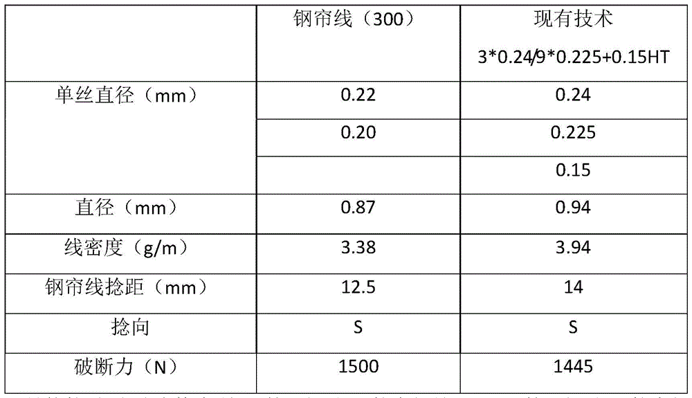
Specifically, as shown in the above table, the diameter of the first steel wire 11 is 0.22mm, the diameter of the second steel wire 21 is 0.20mm, and the first steel wire 11 and the second steel wire 21 are twisted with a twisting length S of 12.5mm to form a steel cord 10 with a diameter of 12.5mm, wherein the breaking force of the steel cord 10 is 1500N.
In combination with the above embodiment, the steel cord of the present utility model adopts a 3+9 structure for twisting, and three first steel wires are used as a strand core and nine second steel wires twisted on the outer wall of the strand core are twisted with the same twisting distance and twisting direction, so that the first steel wires and the second steel wires form line contact, the contact area and contact pressure between the first steel wires and the second steel wires are reduced, and the stress concentration phenomenon generated between the first steel wires and the second steel wires is reduced, thereby effectively reducing abrasion between the steel wires and fracture linearity of the steel wires to improve the service life of the tire.
While the utility model has been described with reference to preferred embodiments, it is not intended to be limiting. Those skilled in the art will appreciate that various modifications and adaptations can be made without departing from the spirit and scope of the present utility model. Accordingly, the scope of the utility model is defined by the appended claims.
Claims (9)
1. A double-layer steel cord structure for a tire carcass, characterized by comprising an inner layer strand core (1) and an outer layer strand core (2);
the inner layer strand core (1) comprises three first steel wires (11), the three first steel wires (11) are twisted with each other, so that the cross-section structure of the connecting line of the central points of the three first steel wires (11) is distributed in a triangle shape, and one side of the triangle is defined by every two first steel wires (11);
the outer layer strand core (2) comprises nine second steel wires (21), wherein the nine second steel wires (21) are twisted outside the first steel wires (11), and each three are used as a group and are linearly arranged on one side of the triangle;
the second steel wires (21) of each group are positioned in the middle and are tangent to the two first steel wires at the corresponding sides of the triangle, the lay lengths of the inner layer strand core (1) and the outer layer strand core (2) are the same, and the first steel wires (11) and the second steel wires (21) form line contact.
2. A double layer steel cord structure for a tire carcass according to claim 1, characterized in that the lay lengths of the first steel wire (11) and the second steel wire (21) are each 9.5 to 15mm.
3. A double layer steel cord structure for a tire carcass according to claim 1, characterized in that the lay lengths of the first steel wire (11) and the second steel wire (21) are each 12.5mm.
4. A double layer steel cord structure for a tire carcass according to claim 1, characterized in that the twisting directions of the first steel filaments (11) and the second steel filaments (21) are both S-twists.
5. A double-layer steel cord structure for a tire carcass according to claim 1, characterized in that the diameter of the first steel wire (11) is 0.20 to 0.24mm and the diameter of the second steel wire (21) is 0.17 to 0.22mm.
6. A double-layer steel cord structure for a tire carcass according to claim 1, characterized in that the diameter of the first steel wire (11) is 0.24mm and the diameter of the second steel wire (21) is 0.20mm.
7. A double-layer steel cord structure for a tire carcass according to claim 1, characterized in that the tensile strength of the first steel wire (11) and the second steel wire (21) is 3900 to 40 mpa.
8. A double layer steel cord structure for a tire carcass according to claim 1, characterized in that the wire cord (10) has a linear density of 3.38g/m.
9. A double layer steel cord structure for a tire carcass according to claim 1, characterized in that the steel cord (10) breaking force is 1500N.
Priority Applications (1)
| Application Number | Priority Date | Filing Date | Title |
|---|---|---|---|
| CN202223164494.6U CN218893896U (en) | 2022-11-28 | 2022-11-28 | Double-layer steel cord structure for tire carcass |
Applications Claiming Priority (1)
| Application Number | Priority Date | Filing Date | Title |
|---|---|---|---|
| CN202223164494.6U CN218893896U (en) | 2022-11-28 | 2022-11-28 | Double-layer steel cord structure for tire carcass |
Publications (1)
| Publication Number | Publication Date |
|---|---|
| CN218893896U true CN218893896U (en) | 2023-04-21 |
Family
ID=85996017
Family Applications (1)
| Application Number | Title | Priority Date | Filing Date |
|---|---|---|---|
| CN202223164494.6U Active CN218893896U (en) | 2022-11-28 | 2022-11-28 | Double-layer steel cord structure for tire carcass |
Country Status (1)
| Country | Link |
|---|---|
| CN (1) | CN218893896U (en) |
-
2022
- 2022-11-28 CN CN202223164494.6U patent/CN218893896U/en active Active
Similar Documents
| Publication | Publication Date | Title |
|---|---|---|
| EP2065511B1 (en) | Rubber reinforcing steel cord and pneumatic radial tire | |
| EP3202977B1 (en) | Steel cord for reinforcing rubber article, and pneumatic tire using same | |
| WO2009151127A1 (en) | Steel cord for reinforcement of rubber product and pneumatic tire using same | |
| JP6400972B2 (en) | Steel cord for rubber article reinforcement | |
| CN109281026B (en) | Meridian steel cord with high rubber permeability | |
| CN110735340A (en) | A seventeen-strand radial tire steel cord | |
| CN113550037A (en) | Nylon cord and tire thereof | |
| CN222923516U (en) | Steel cord structure for engineering radial tire | |
| CN111535062A (en) | Steel wire cord for 1+ 7-ply radial tire | |
| CN112359623A (en) | Steel wire cord for improving glue layer infiltration | |
| CN112127187A (en) | A kind of steel cord for radial engineering tire | |
| CN218893892U (en) | Steel cord structure for all-steel radial tire body | |
| US6119747A (en) | 2+9 Steel cords for the reinforcement of rubber articles and pneumatic radial tires using the same | |
| JP2007107136A (en) | Steel cord for reinforcing rubber article and pneumatic radial tire | |
| CN217419126U (en) | Compact steel cord with 2+ N structure | |
| CN117758526A (en) | Steel cord for hypertonic rubber radial engineering tire and preparation method thereof | |
| CN112359624A (en) | N-layer intensive reinforced steel wire cord | |
| CN214219196U (en) | N-layer intensive reinforced steel wire cord | |
| CN113293632A (en) | Compact steel cord with 2+ M + N structure and manufacturing method thereof | |
| JP4097812B2 (en) | Steel cords for reinforcing rubber articles and pneumatic tires | |
| JP2006291376A (en) | Steel cord for rubber reinforcement and pneumatic radial tire | |
| CN222251503U (en) | Multilayer high-strength steel cord | |
| JP2018176923A (en) | Pneumatic radial tire | |
| CN112359621A (en) | Steel wire cord for engineering tire | |
| CN222923515U (en) | Steel cord structure for engineering radial tire framework material |
Legal Events
| Date | Code | Title | Description |
|---|---|---|---|
| GR01 | Patent grant | ||
| GR01 | Patent grant |