CN218868932U - A garden watering device for municipal engineering - Google Patents
A garden watering device for municipal engineering Download PDFInfo
- Publication number
- CN218868932U CN218868932U CN202222957521.9U CN202222957521U CN218868932U CN 218868932 U CN218868932 U CN 218868932U CN 202222957521 U CN202222957521 U CN 202222957521U CN 218868932 U CN218868932 U CN 218868932U
- Authority
- CN
- China
- Prior art keywords
- control box
- water storage
- spray
- storage control
- municipal engineering
- Prior art date
- Legal status (The legal status is an assumption and is not a legal conclusion. Google has not performed a legal analysis and makes no representation as to the accuracy of the status listed.)
- Expired - Fee Related
Links
Images


Classifications
-
- Y—GENERAL TAGGING OF NEW TECHNOLOGICAL DEVELOPMENTS; GENERAL TAGGING OF CROSS-SECTIONAL TECHNOLOGIES SPANNING OVER SEVERAL SECTIONS OF THE IPC; TECHNICAL SUBJECTS COVERED BY FORMER USPC CROSS-REFERENCE ART COLLECTIONS [XRACs] AND DIGESTS
- Y02—TECHNOLOGIES OR APPLICATIONS FOR MITIGATION OR ADAPTATION AGAINST CLIMATE CHANGE
- Y02A—TECHNOLOGIES FOR ADAPTATION TO CLIMATE CHANGE
- Y02A40/00—Adaptation technologies in agriculture, forestry, livestock or agroalimentary production
- Y02A40/10—Adaptation technologies in agriculture, forestry, livestock or agroalimentary production in agriculture
- Y02A40/22—Improving land use; Improving water use or availability; Controlling erosion
Landscapes
- Nozzles (AREA)
Abstract
本实用新型涉及园林浇灌装置技术领域,公开了一种市政工程用园林浇灌装置,包括储水控制箱,所述储水控制箱的底部安装有安装板,所述安装板的底部设置有多个安装套;本装置设置在使用时,可通过喷洒控制箱内的高压泵将水抽出,再配合喷雾灌溉喷头内的喷嘴将水珠大范围喷出,通过加固套与弧形槽的配合使用,确保洒水管支撑结构稳固,还可确保手持喷枪进行市政工程园林浇灌时结构稳定,实现了能够同时进行大范围的喷洒和小范围地浇灌的目的,使用时较为灵活;本装置设置有放置稳定机构,可方便地完成踩踏板和定位柱位置的固定,且通过踩踏板和定位柱增强储水控制箱锁死后放置的稳定性,提升了本装置放置使用时的稳定性。
The utility model relates to the technical field of garden watering devices, and discloses a garden watering device for municipal engineering, comprising a water storage control box, the bottom of the water storage control box is installed with a mounting plate, and the bottom of the Installation sleeve; when the device is set in use, the water can be pumped out through the high-pressure pump in the spray control box, and then the nozzles in the spray irrigation nozzle can be used to spray water droplets in a wide range. To ensure the stability of the support structure of the sprinkler pipe, it can also ensure the stability of the structure when the hand-held spray gun is used for watering municipal engineering gardens, achieving the purpose of simultaneously spraying in a large area and watering in a small area, and it is more flexible in use; this device is equipped with a stable placement mechanism , can conveniently complete the fixing of the position of the pedal and the positioning post, and enhance the stability of the water storage control box after being locked by stepping on the pedal and the positioning post, and improve the stability of the device when it is placed and used.
Description
技术领域technical field
本实用新型涉及园林浇灌装置技术领域,具体是一种市政工程用园林浇灌装置。The utility model relates to the technical field of garden watering devices, in particular to a garden watering device for municipal engineering.
背景技术Background technique
市政工程是指市政基础设施建设工程,园林指特定培养的自然环境和游憩境域。在一定的地域运用工程技术和艺术手段,通过改造地形(或进一步筑山、叠石、理水)、种植树木花草、营造建筑和布置园路等途径创作而成的美的自然环境和游憩境域,就称为园林,园林是常见的市政工程建筑,市政工程园林在对植物浇灌时,不同观赏植物的需水规律不同,应根据植物类型和对灌溉的要求采用适当的方法和设备;Municipal engineering refers to municipal infrastructure construction projects, and gardens refer to specially cultivated natural environments and recreational areas. Using engineering technology and artistic means in a certain area to create a beautiful natural environment and recreational environment by transforming the terrain (or further building mountains, stacking stones, and water management), planting trees and flowers, building buildings, and arranging garden roads, etc. It is called a garden. Gardens are common municipal engineering buildings. When watering plants in municipal engineering gardens, different ornamental plants have different water requirements. Appropriate methods and equipment should be used according to plant types and irrigation requirements;
但是,现有的浇灌设备在使用过程中,不易同时进行大范围的喷洒和小范围地浇灌,使用时具有一定局限性,使用不够灵活。因此,本领域技术人员提供了一种市政工程用园林浇灌装置,以解决上述背景技术中提出的问题。However, the existing watering equipment is not easy to perform large-scale spraying and small-scale watering at the same time during use, and has certain limitations during use, and the use is not flexible enough. Therefore, those skilled in the art provide a garden watering device for municipal engineering to solve the problems raised in the above-mentioned background technology.
实用新型内容Utility model content
本实用新型的目的在于提供一种市政工程用园林浇灌装置,以解决上述背景技术中提出的问题。The purpose of this utility model is to provide a garden watering device for municipal engineering, so as to solve the problems raised in the above-mentioned background technology.
为实现上述目的,本实用新型提供如下技术方案:In order to achieve the above object, the utility model provides the following technical solutions:
一种市政工程用园林浇灌装置,包括储水控制箱,所述储水控制箱的底部安装有安装板,所述安装板的底部设置有多个安装套,所述安装套的内部通过转轴转动连接有滚轮,所述储水控制箱的顶部安装有喷洒控制箱,所述喷洒控制箱的顶部设置有喷雾灌溉喷头,所述喷洒控制箱的外侧安装有稳固机构,所述储水控制箱的两侧均设置有放置稳定机构,所述喷洒控制箱的顶部固定有把手架,所述储水控制箱的顶部连接有洒水管,所述洒水管的一端安装有球阀,所述球阀的外侧连接有喷枪接管,所述喷枪接管的一端连接有手持喷枪;A garden watering device for municipal engineering, comprising a water storage control box, a mounting plate is installed on the bottom of the water storage control box, and a plurality of mounting sleeves are arranged on the bottom of the mounting plate, and the inside of the mounting sleeve is rotated by a rotating shaft Connected with rollers, the top of the water storage control box is equipped with a spray control box, the top of the spray control box is provided with a spray irrigation nozzle, the outside of the spray control box is equipped with a stabilizing mechanism, the water storage control box Both sides are provided with a stable mechanism, the top of the spraying control box is fixed with a handle frame, the top of the water storage control box is connected with a sprinkler pipe, one end of the sprinkler pipe is installed with a ball valve, and the outside of the ball valve is connected to A spray gun connection is provided, and one end of the spray gun connection is connected with a hand-held spray gun;
所述稳固机构包括金属壳体,所述金属壳体的内底壁设置有安装弹簧,所述安装弹簧的顶部设置有移动板,所述移动板的顶部固定有移动柱,所述移动柱的顶部设置有防滑板,所述移动柱的外侧设置有定位块,所述金属壳体的内部开设有弧形槽,所述移动板的底部安装有加固套,所述金属壳体的内部滑动连接有导向块,所述导向块的顶部固定有限位垫。The stabilizing mechanism includes a metal shell, the inner bottom wall of the metal shell is provided with a mounting spring, the top of the mounting spring is provided with a moving plate, the top of the moving plate is fixed with a moving column, and the moving column is fixed on the top of the moving plate. An anti-skid plate is provided on the top, a positioning block is provided on the outside of the moving column, an arc-shaped groove is opened inside the metal shell, a reinforcing sleeve is installed on the bottom of the moving plate, and the inside of the metal shell is slidingly connected There is a guide block, and the top of the guide block is fixed with a spacer pad.
作为本实用新型再进一步的方案:所述放置稳定机构包括固定板,所述固定板的顶部设置有贯穿其底部的螺纹柱,所述螺纹柱的底部固定有踩踏板,所述踩踏板的底部设置有定位柱,所述螺纹柱的外侧安装有防滑垫,所述螺纹柱的外侧活动套接有两个垫片,所述螺纹柱的外侧螺纹连接有两个金属螺母。As a further solution of the present utility model: the placement stabilization mechanism includes a fixed plate, the top of the fixed plate is provided with a threaded column that runs through the bottom of the fixed plate, the bottom of the threaded column is fixed with a pedal, and the bottom of the pedal is A positioning post is provided, an anti-skid pad is installed on the outside of the threaded post, two gaskets are movably sleeved on the outside of the threaded post, and two metal nuts are threaded on the outside of the threaded post.
作为本实用新型再进一步的方案:所述固定板的一侧嵌入固定在所述储水控制箱的内部,所述金属螺母的外侧设置有防滑纹。As a further solution of the present invention: one side of the fixing plate is embedded and fixed inside the water storage control box, and the outer side of the metal nut is provided with anti-slip lines.
作为本实用新型再进一步的方案:所述固定板的内部开设有通孔,且该通孔的尺寸与所述螺纹柱的尺寸适配。As a further solution of the present invention: a through hole is opened inside the fixing plate, and the size of the through hole is adapted to the size of the threaded column.
作为本实用新型再进一步的方案:所述金属壳体的内部开设有与所述定位块尺寸适配的凹槽,所述金属壳体与所述储水控制箱之间焊接固定。As a further solution of the present invention: the metal housing is provided with a groove matching the size of the positioning block, and the metal housing is welded and fixed to the water storage control box.
作为本实用新型再进一步的方案:所述喷洒控制箱的内部安装有高压泵,所述喷雾灌溉喷头的内部设置有喷嘴。As a further solution of the utility model: a high-pressure pump is installed inside the spray control box, and a nozzle is arranged inside the spray irrigation nozzle.
与现有技术相比,本实用新型的有益效果是:Compared with the prior art, the beneficial effects of the utility model are:
1、本装置设置在使用时,可通过喷洒控制箱内的高压泵将水抽出,再配合喷雾灌溉喷头内的喷嘴将水珠大范围喷出,实现将水珠送到大范围和远距离喷灌的效果,通过加固套与弧形槽的配合使用,确保洒水管支撑结构稳固,还可确保手持喷枪进行市政工程园林浇灌时结构稳定,实现了能够同时进行大范围的喷洒和小范围地浇灌的目的,使用时较为灵活;1. When the device is set in use, the water can be pumped out through the high-pressure pump in the spray control box, and then cooperate with the nozzles in the spray irrigation nozzle to spray the water droplets in a wide range, so as to realize the delivery of water droplets to a wide range and long-distance spray irrigation Through the combined use of the reinforcement sleeve and the arc-shaped groove, the support structure of the sprinkler pipe is ensured to be stable, and the structure is also ensured to be stable when the hand-held spray gun is used for watering municipal engineering gardens. Purpose, more flexible in use;
2、本装置设置有放置稳定机构,当储水控制箱需要放置在固定位置并使用时,可方便地完成踩踏板和定位柱位置的固定,且通过踩踏板和定位柱增强储水控制箱锁死后放置的稳定性,提升了本装置放置使用时的稳定性。2. The device is equipped with a stable placement mechanism. When the water storage control box needs to be placed in a fixed position and used, it can conveniently complete the fixing of the position of the pedal and the positioning post, and strengthen the lock of the water storage control box by stepping on the pedal and the positioning post The stability of placing after death improves the stability of the device when placed in use.
附图说明Description of drawings
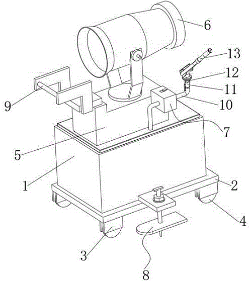
图1为一种市政工程用园林浇灌装置的立体图;Fig. 1 is a perspective view of a garden watering device for municipal engineering;
图2为一种市政工程用园林浇灌装置中稳固机构的结构示意图;Fig. 2 is a structural schematic diagram of a stabilizing mechanism in a garden watering device for municipal engineering;
图3为一种市政工程用园林浇灌装置中放置稳定机构的立体图。Fig. 3 is a perspective view of a stabilizing mechanism placed in a garden watering device for municipal engineering.
图中:1、储水控制箱;2、安装板;3、安装套;4、滚轮;5、喷洒控制箱;6、喷雾灌溉喷头;7、稳固机构;71、金属壳体;72、安装弹簧;73、移动板;74、移动柱;75、防滑板;76、定位块;77、弧形槽;78、加固套;79、导向块;710、限位垫;8、放置稳定机构;81、固定板;82、螺纹柱;83、踩踏板;84、定位柱;85、防滑垫;86、垫片;87、金属螺母;9、把手架;10、洒水管;11、球阀;12、喷枪接管;13、手持喷枪。In the figure: 1. Water storage control box; 2. Mounting plate; 3. Mounting sleeve; 4. Roller; 5. Sprinkling control box; 6. Spray irrigation nozzle; 7. Stabilizing mechanism; Spring; 73, moving plate; 74, moving column; 75, anti-skid plate; 76, positioning block; 77, arc groove; 78, reinforcement sleeve; 79, guide block; 710, limit pad; 81, fixed plate; 82, threaded column; 83, pedal; 84, positioning column; 85, anti-skid pad; 86, gasket; 87, metal nut; 9, handle frame; 10, sprinkler pipe; 11, ball valve; 12 , Spray gun to take over; 13, Hand-held spray gun.
具体实施方式Detailed ways
下面将结合本实用新型实施例中的附图,对本实用新型实施例中的技术方案进行清楚、完整地描述,显然,所描述的实施例仅仅是本实用新型一部分实施例,而不是全部的实施例。基于本实用新型中的实施例,本领域普通技术人员在没有做出创造性劳动前提下所获得的所有其他实施例,都属于本实用新型保护的范围。The technical solutions in the embodiments of the present invention will be clearly and completely described below in conjunction with the accompanying drawings in the embodiments of the present invention. Obviously, the described embodiments are only part of the embodiments of the present invention, not all of them. example. Based on the embodiments of the present utility model, all other embodiments obtained by persons of ordinary skill in the art without making creative efforts belong to the scope of protection of the present utility model.
请参阅图1-3,本实用新型实施例中,一种市政工程用园林浇灌装置,包括储水控制箱1,储水控制箱1的底部安装有安装板2,安装板2的底部设置有多个安装套3,安装套3的内部通过转轴转动连接有滚轮4,储水控制箱1的顶部安装有喷洒控制箱5,喷洒控制箱5的顶部设置有喷雾灌溉喷头6,喷洒控制箱5的内部安装有高压泵,喷雾灌溉喷头6的内部设置有喷嘴,喷洒控制箱5的外侧安装有稳固机构7,储水控制箱1的两侧均设置有放置稳定机构8,喷洒控制箱5的顶部固定有把手架9,储水控制箱1的顶部连接有洒水管10,洒水管10的一端安装有球阀11,球阀11的外侧连接有喷枪接管12,喷枪接管12的一端连接有手持喷枪13;Please refer to Fig. 1-3, in the embodiment of the present utility model, a kind of garden watering device for municipal engineering, comprises water
稳固机构7包括金属壳体71,金属壳体71的内底壁设置有安装弹簧72,安装弹簧72的顶部设置有移动板73,移动板73的顶部固定有移动柱74,移动柱74的顶部设置有防滑板75,移动柱74的外侧设置有定位块76,金属壳体71的内部开设有与定位块76尺寸适配的凹槽,金属壳体71与储水控制箱1之间焊接固定,金属壳体71的内部开设有弧形槽77,移动板73的底部安装有加固套78,金属壳体71的内部滑动连接有导向块79,导向块79的顶部固定有限位垫710,可通过喷洒控制箱5内的高压泵将水抽出,再配合喷雾灌溉喷头6内的喷嘴将水珠大范围喷出,实现将水珠送到大范围和远距离喷灌的效果,同时通过喷枪接管12和手持喷枪13的配合使用,操作者可握持手持喷枪13的外侧,并在启动洒水管10后使用手持喷枪13进行小范围地浇灌,且洒水管10在使用时能够贯穿金属壳体71,按压防滑板75时可带动移动柱74和移动板73竖直方向移动,移动柱74外侧的定位块76能够卡入金属壳体71预设的凹槽内,而移动板73底部的加固套78能够贴合在对应洒水管10的外侧,水平方向推动限位垫710后,限位垫710的下底面与防滑板75的上顶面贴合,起到对防滑板75和移动柱74限位的目的,通过加固套78与弧形槽77的配合使用,确保洒水管10支撑结构稳固,还可确保手持喷枪13进行市政工程园林浇灌时结构稳定。The stabilizing
作为本实用新型的一种实施方式,放置稳定机构8包括固定板81,固定板81的顶部设置有贯穿其底部的螺纹柱82,固定板81的内部开设有通孔,且该通孔的尺寸与螺纹柱82的尺寸适配,螺纹柱82的底部固定有踩踏板83,踩踏板83的底部设置有定位柱84,螺纹柱82的外侧安装有防滑垫85,螺纹柱82的外侧活动套接有两个垫片86,螺纹柱82的外侧螺纹连接有两个金属螺母87,固定板81的一侧嵌入固定在储水控制箱1的内部,金属螺母87的外侧设置有防滑纹,当储水控制箱1需要放置在固定位置并使用时,安装套3一般本身具有锁死滚轮4的锁死机构,但锁死后仍可能小幅度晃动,此时螺纹柱82外侧的两个金属螺母87均远离固定板81,可竖直方向踩踏对应的踩踏板83,使踩踏板83底部的定位柱84插入泥土内,随后可转动两个金属螺母87,使垫片86的对应面牢固贴合在固定板81外侧,从而方便地完成踩踏板83和定位柱84位置的固定,且通过踩踏板83和定位柱84增大储水控制箱1锁死后放置的稳定性。As an embodiment of the present utility model, the
本实用新型的工作原理是:本装置设置在使用时,可通过喷洒控制箱5内的高压泵将水抽出,再配合喷雾灌溉喷头6内的喷嘴将水珠大范围喷出,实现将水珠送到大范围和远距离喷灌的效果,同时通过喷枪接管12和手持喷枪13的配合使用,操作者可握持手持喷枪13的外侧,并在启动洒水管10后使用手持喷枪13进行小范围地浇灌,且洒水管10在使用时能够贯穿金属壳体71,按压防滑板75时可带动移动柱74和移动板73竖直方向移动,移动柱74外侧的定位块76能够卡入金属壳体71预设的凹槽内,而移动板73底部的加固套78能够贴合在对应洒水管10的外侧,水平方向推动限位垫710后,限位垫710的下底面与防滑板75的上顶面贴合,起到对防滑板75和移动柱74限位的目的,通过加固套78与弧形槽77的配合使用,确保洒水管10支撑结构稳固,还可确保手持喷枪13进行市政工程园林浇灌时结构稳定,实现了能够同时进行大范围的喷洒和小范围地浇灌的目的,使用时较为灵活;本装置设置有放置稳定机构8,当储水控制箱1需要放置在固定位置并使用时,安装套3一般本身具有锁死滚轮4的锁死机构,但锁死后仍可能小幅度晃动,此时螺纹柱82外侧的两个金属螺母87均远离固定板81,可竖直方向踩踏对应的踩踏板83,使踩踏板83底部的定位柱84插入泥土内,随后可转动两个金属螺母87,使垫片86的对应面牢固贴合在固定板81外侧,从而方便地完成踩踏板83和定位柱84位置的固定,且通过踩踏板83和定位柱84增大储水控制箱1锁死后放置的稳定性,提升了本装置放置使用时的稳定性。The working principle of the utility model is: when the device is set in use, the water can be pumped out by the high-pressure pump in the
以上的,仅为本实用新型较佳的具体实施方式,但本实用新型的保护范围并不局限于此,任何熟悉本技术领域的技术人员在本实用新型揭露的技术范围内,根据本实用新型的技术方案及其实用新型构思加以等同替换或改变,都应涵盖在本实用新型的保护范围之内。The above are only preferred specific implementations of the utility model, but the scope of protection of the utility model is not limited thereto, and any skilled person familiar with the technical field within the technical scope disclosed in the utility model, according to the utility model Any equivalent replacement or change of the technical solution and the concept of the utility model shall be covered by the protection scope of the utility model.
Claims (6)
Priority Applications (1)
| Application Number | Priority Date | Filing Date | Title |
|---|---|---|---|
| CN202222957521.9U CN218868932U (en) | 2022-11-07 | 2022-11-07 | A garden watering device for municipal engineering |
Applications Claiming Priority (1)
| Application Number | Priority Date | Filing Date | Title |
|---|---|---|---|
| CN202222957521.9U CN218868932U (en) | 2022-11-07 | 2022-11-07 | A garden watering device for municipal engineering |
Publications (1)
| Publication Number | Publication Date |
|---|---|
| CN218868932U true CN218868932U (en) | 2023-04-18 |
Family
ID=85952332
Family Applications (1)
| Application Number | Title | Priority Date | Filing Date |
|---|---|---|---|
| CN202222957521.9U Expired - Fee Related CN218868932U (en) | 2022-11-07 | 2022-11-07 | A garden watering device for municipal engineering |
Country Status (1)
| Country | Link |
|---|---|
| CN (1) | CN218868932U (en) |
Cited By (1)
| Publication number | Priority date | Publication date | Assignee | Title |
|---|---|---|---|---|
| CN121713844A (en) * | 2026-01-22 | 2026-03-24 | 宝鸡植物园 | Intelligent irrigation device and method for garden engineering |
-
2022
- 2022-11-07 CN CN202222957521.9U patent/CN218868932U/en not_active Expired - Fee Related
Cited By (1)
| Publication number | Priority date | Publication date | Assignee | Title |
|---|---|---|---|---|
| CN121713844A (en) * | 2026-01-22 | 2026-03-24 | 宝鸡植物园 | Intelligent irrigation device and method for garden engineering |
Similar Documents
| Publication | Publication Date | Title |
|---|---|---|
| CN107231831A (en) | Plant equipment in a kind of gardens meadow for municipal works | |
| CN115644024A (en) | A water-saving irrigation equipment for afforestation | |
| CN214801329U (en) | Afforestation conversion equipment that waters | |
| CN205052615U (en) | Landscape plant sprinkling irrigation equipment | |
| CN207428050U (en) | A kind of municipal administration gardens water injector | |
| CN215223689U (en) | Watering device for view engineering | |
| CN221749217U (en) | A garden plant maintenance sprinkler system | |
| CN217771064U (en) | Irrigation equipment for afforestation | |
| CN116548284A (en) | A sprinkler device for gardens with adjustable spraying range | |
| CN217826221U (en) | Water-saving irrigation equipment for landscaping engineering | |
| CN205727418U (en) | Portable movable gardens rainer | |
| CN205695202U (en) | A kind of farmland pouring chemical spraying device | |
| CN220965902U (en) | Portable sprinkler of trees watering for afforestation | |
| CN219628532U (en) | An easily adjustable sprinkler irrigation device for landscaping | |
| CN219042507U (en) | Garden Slope Greening Structure | |
| CN218163855U (en) | A portable watering device for landscaping maintenance | |
| CN214430816U (en) | Gardens sprinkling irrigation equipment that shower nozzle can carry out rotation regulation | |
| CN219373326U (en) | Irrigation equipment that gardens were used | |
| CN221784899U (en) | A landscaping maintenance device | |
| CN222532415U (en) | Gardens flowers maintenance spraying equipment | |
| CN218104405U (en) | A sprinkler water-saving device for landscaping | |
| CN223322660U (en) | A precise irrigation device for Chinese medicinal material planting | |
| CN215422439U (en) | A convenient laxative device for afforestation | |
| CN217850564U (en) | Lawn paver for landscaping | |
| CN219046953U (en) | An adjustable irrigation device |
Legal Events
| Date | Code | Title | Description |
|---|---|---|---|
| GR01 | Patent grant | ||
| GR01 | Patent grant | ||
| CF01 | Termination of patent right due to non-payment of annual fee |
Granted publication date: 20230418 |
|
| CF01 | Termination of patent right due to non-payment of annual fee |