CN218857702U - Welding table - Google Patents
Welding table Download PDFInfo
- Publication number
- CN218857702U CN218857702U CN202222678936.2U CN202222678936U CN218857702U CN 218857702 U CN218857702 U CN 218857702U CN 202222678936 U CN202222678936 U CN 202222678936U CN 218857702 U CN218857702 U CN 218857702U
- Authority
- CN
- China
- Prior art keywords
- fixedly connected
- sliding
- screw rod
- seat
- plate
- Prior art date
- Legal status (The legal status is an assumption and is not a legal conclusion. Google has not performed a legal analysis and makes no representation as to the accuracy of the status listed.)
- Active
Links
- 238000003466 welding Methods 0.000 title claims abstract description 25
- 230000001105 regulatory effect Effects 0.000 claims abstract description 8
- 230000002457 bidirectional effect Effects 0.000 claims description 20
- 230000005540 biological transmission Effects 0.000 claims description 13
- 239000004033 plastic Substances 0.000 abstract description 18
- 229920003023 plastic Polymers 0.000 abstract description 18
- 230000009286 beneficial effect Effects 0.000 abstract description 2
- 238000000034 method Methods 0.000 description 3
- 230000008569 process Effects 0.000 description 3
- 238000012644 addition polymerization Methods 0.000 description 1
- 230000004075 alteration Effects 0.000 description 1
- 150000001875 compounds Chemical class 0.000 description 1
- 238000010586 diagram Methods 0.000 description 1
- 239000000835 fiber Substances 0.000 description 1
- 230000007246 mechanism Effects 0.000 description 1
- 238000012986 modification Methods 0.000 description 1
- 230000004048 modification Effects 0.000 description 1
- 239000000178 monomer Substances 0.000 description 1
- 238000012643 polycondensation polymerization Methods 0.000 description 1
- 239000002994 raw material Substances 0.000 description 1
- 238000006467 substitution reaction Methods 0.000 description 1
- 230000007306 turnover Effects 0.000 description 1
Images

Landscapes
- Tables And Desks Characterized By Structural Shape (AREA)
Abstract
The utility model discloses a welding table, which comprises a fixed plate, wherein a supporting seat is symmetrically and fixedly connected with the outer side of the fixed plate, a sliding seat is slidably connected with the inner part of the supporting seat, an adjusting seat is fixedly connected with the top of the sliding seat, a workbench is fixedly connected with the top of the adjusting seat, a sliding block is symmetrically and slidably connected with the top of the workbench, a sliding plate is fixedly connected with the top of the sliding block, a rotating shaft is rotatably connected with one side of the sliding plate, a rotating plate is fixedly connected with one end of the rotating shaft, and an adjusting block is symmetrically and slidably connected with one side of the rotating plate; the utility model discloses the beneficial effect who reaches is: the sliding seat, the adjusting seat and the connecting screw rod are arranged to realize the function of adjusting the height of the workbench, so that people with different heights can use the workbench conveniently; the rotating shaft and the rotating plate are arranged to realize the function of overturning the plastic accessories; through having set up regulating block and grip block and realized carrying out the fixed function of centre gripping to the plastics accessory, conveniently weld convenient to use.
Description
Technical Field
The utility model relates to a welding bench technical field specifically is a welding bench.
Background
The plastic is a high molecular compound which is polymerized by monomer serving as a raw material through addition polymerization or condensation polymerization, the deformation resistance of the plastic is moderate and is between fiber and rubber, the non-stick plastic is one of plastics, and a welding table is needed in the welding process of plastic accessories; in chinese utility model patent application no: CN202120759154.4 discloses an ultrasonic welding device for plastic accessories, wherein a clamping mechanism is arranged on the surface of a workbench below an ultrasonic welding machine, a control power supply of an electric pushing cylinder is switched on, the plastic accessories are placed between clamping plates, a front end telescopic rod of the electric pushing cylinder is electrified to extend outwards to push the clamping plates, the clamping plates transversely move in a guide groove through a guide block, the two clamping plates which transversely move can be stably clamped on two sides of the plastic accessories for clamping and fixing, the plastic accessories can be clamped and welded, the telescopic rod of the electric pushing cylinder can pull the clamping plates backwards to return to the original position after retracting, and clamping force of the plastic accessories is relieved. Although above-mentioned patent has realized the grip function to plastic accessories, current welding bench highly most fixed, be not convenient for adjust according to user's height, and can't overturn plastic accessories, need artifical upset when accomplishing the welding of a face and just can carry out subsequent welding after fixing again, the step is loaded down with trivial details, the use in the reality of not being convenient for.
SUMMERY OF THE UTILITY MODEL
An object of the utility model is to provide a welding bench to the high most fixed that proposes in solving above-mentioned background art, be not convenient for adjust according to user's height, and can't overturn the plastic accessories, need artifical upset when accomplishing the welding of a face and just can carry out subsequent welding after fixing again, the loaded down with trivial details problem of step.
In order to achieve the above purpose, the utility model provides a following technical scheme:
the utility model provides a welding table, includes the fixed plate, the outside symmetry fixedly connected with supporting seat of fixed plate, the inside sliding connection of supporting seat has the sliding seat, the top fixedly connected with of sliding seat adjusts the seat, the top fixedly connected with workstation of adjusting the seat, the top symmetry sliding connection of workstation has the slider, the top fixedly connected with sliding plate of slider, one side of sliding plate is rotated and is connected with the pivot, the one end fixedly connected with rotor plate of pivot, one side symmetry sliding connection of rotor plate has the regulating block, one side fixedly connected with grip block of regulating block, one side of grip block is equipped with the rubber pad.
Preferably, the inside of the supporting seat is rotatably connected with a connecting screw rod, and the sliding seat is in threaded connection with the connecting screw rod.
Preferably, the outer side of the fixing plate is rotatably connected with a transmission shaft, the outer side of the transmission shaft is fixedly connected with second bevel gears at equal intervals, one end of the connecting screw rod is fixedly connected with a first bevel gear matched with the second bevel gear for use, and one end of the transmission shaft is fixedly connected with a handle.
Preferably, a tool box is fixedly connected to the top of the fixing plate.
Preferably, the inside of the workbench is rotatably connected with a first bidirectional screw rod, and the sliding block is in threaded connection with the first bidirectional screw rod.
Preferably, the outer side of the sliding plate is fixedly connected with a motor, the output end of the motor is fixedly connected with the rotating shaft, the outer side of the workbench is provided with a control panel, and the motor is electrically connected with the control panel.
Preferably, a second bidirectional screw rod is rotatably connected to the inside of the rotating plate, the adjusting block is in threaded connection with the second bidirectional screw rod, and one end of the second bidirectional screw rod is fixedly connected with a knob.
The utility model discloses the beneficial effect who reaches is: the sliding seat, the adjusting seat and the connecting screw rod are arranged to realize the function of adjusting the height of the workbench, so that people with different heights can use the workbench conveniently; the rotating shaft and the rotating plate are arranged to realize the function of overturning the plastic accessories; through having set up regulating block and grip block and realized carrying out the fixed function of centre gripping to the plastics accessory, conveniently weld convenient to use.
Drawings
The accompanying drawings are included to provide a further understanding of the invention, and are incorporated in and constitute a part of this specification, illustrate embodiments of the invention, and together with the description serve to explain the invention and not to limit the invention. In the drawings:
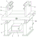
fig. 1 is a schematic structural diagram of the present invention;
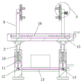
fig. 2 is a cross-sectional view of the present invention;
fig. 3 is an enlarged view of a part a of the present invention.
In the figure: 1. a work table; 2. an adjusting seat; 3. a supporting base; 4. a fixing plate; 5. a tool box; 6. a motor; 7. a clamping plate; 8. a rotating plate; 9. a sliding plate; 10. connecting a screw rod; 11. a sliding seat; 12. a first bevel gear; 13. a drive shaft; 14. a second bevel gear; 15. a slider; 16. a first bidirectional screw; 17. an adjusting block; 18. a second bidirectional screw rod; 19. a rotating shaft; 20. a control panel.
Detailed Description
The technical solutions in the embodiments of the present invention will be described clearly and completely with reference to the drawings in the embodiments of the present invention, and it is obvious that the described embodiments are only some embodiments of the present invention, not all embodiments. Based on the embodiments in the present invention, all other embodiments obtained by a person skilled in the art without creative efforts all belong to the protection scope of the present invention.
Referring to fig. 1 to 3, the present invention provides a technical solution:
a welding table comprises a fixed plate 4, wherein supporting seats 3 are symmetrically and fixedly connected to the outer side of the fixed plate 4, sliding seats 11 are slidably connected to the inner portions of the supporting seats 3, adjusting seats 2 are fixedly connected to the tops of the sliding seats 11, a workbench 1 is fixedly connected to the tops of the adjusting seats 2, the adjusting seats 2 are driven to move through the movement of the sliding seats 11, and the workbench 1 is driven to move through the adjusting seats 2, so that the height is adjusted; the top of the workbench 1 is symmetrically connected with sliding blocks 15 in a sliding manner, the top of each sliding block 15 is fixedly connected with a sliding plate 9, and the sliding plates 9 are driven to move by the movement of the sliding blocks 15, so that the distance between the two sliding plates 9 is adjusted according to the size of an accessory; one side of the sliding plate 9 is rotatably connected with a rotating shaft 19, one end of the rotating shaft 19 is fixedly connected with a rotating plate 8, and the rotating plate 8 is driven to rotate through the rotating shaft 19 so as to turn over the accessory; one side of the rotating plate 8 is symmetrically and slidably connected with an adjusting block 17, one side of the adjusting block 17 is fixedly connected with a clamping plate 7, one side of the clamping plate 7 is provided with a rubber pad, the adjusting block 17 drives the clamping plate 7 to move, and the clamping plate 7 is used for clamping and fixing the accessory.
Furthermore, the inside of the supporting seat 3 is rotatably connected with a connecting screw rod 10, the sliding seat 11 is in threaded connection with the connecting screw rod 10, and the sliding seat 11 is driven to move by the rotation of the connecting screw rod 10.
Furthermore, the outer side of the fixing plate 4 is rotatably connected with a transmission shaft 13, the outer side of the transmission shaft 13 is fixedly connected with second bevel gears 14 at equal intervals, one end of the connecting screw rod 10 is fixedly connected with a first bevel gear 12 used in cooperation with the second bevel gears 14, one end of the transmission shaft 13 is fixedly connected with a handle, the transmission shaft 13 is driven to rotate through the handle, the transmission shaft 13 drives the second bevel gears 14 to rotate, the second bevel gears 14 drive the first bevel gears 12 to rotate, and the first bevel gears 12 drive the connecting screw rod 10 to rotate.
Furthermore, a tool box 5 is fixedly connected to the top of the fixing plate 4, so that tools can be conveniently placed.
Further, a first bidirectional screw rod 16 is rotatably connected inside the workbench 1, the slider 15 is in threaded connection with the first bidirectional screw rod 16, and the slider 15 is driven to move by the rotation of the first bidirectional screw rod 16.
Further, the outside fixedly connected with motor 6 of sliding plate 9, motor 6's output and pivot 19 fixed connection, the outside of workstation 1 is equipped with control panel 20, and motor 6 and control panel 20 electric connection drive pivot 19 through motor 6 and rotate, control the operating condition of motor 6 through control panel 20.
Furthermore, a second bidirectional screw rod 18 is rotatably connected inside the rotating plate 8, the adjusting block 17 is in threaded connection with the second bidirectional screw rod 18, one end of the second bidirectional screw rod 18 is fixedly connected with a knob, the knob drives the second bidirectional screw rod 18 to rotate, and the adjusting block 17 is driven to move through the rotation of the second bidirectional screw rod 18.
Specifically, when the utility model is used, the height of the workbench 1 needs to be adjusted, the transmission shaft 13 is rotated, the second bevel gear 14 is driven to rotate through the rotation of the transmission shaft 13, the second bevel gear 14 drives the first bevel gear 12 to rotate, the first bevel gear 12 drives the connecting lead screw 10 to rotate, the sliding seat 11 is driven to move through the rotation of the connecting lead screw 10, the sliding seat 11 drives the adjusting seat 2 to move, the adjusting seat 2 drives the workbench 1 to move, so that the height is adjusted, and the use of people with different heights is facilitated; rotate first two-way lead screw 16, it removes to drive slider 15 through the rotation of first two-way lead screw 16, slider 15 drives sliding plate 9 and removes, adjust the interval between two sliding plates 9 according to the size of the plastics accessory of will processing, be close to rotor plate 8 with the accessory, rotate second two-way lead screw 18, it removes to drive regulating block 17 through the rotation of second two-way lead screw 18, regulating block 17 drives grip block 7 and removes and carries out the centre gripping to the accessory and fix, can carry out welding process, when needing the upset, starting motor 6, drive pivot 19 through motor 6 and rotate, pivot 19 drives rotor plate 8 and rotates and can overturn the accessory, be convenient for process.
In the description of the present invention, it is to be understood that the terms "coaxial", "bottom", "one end", "top", "middle", "other end", "upper", "one side", "top", "inner", "front", "center", "both ends", and the like, indicate orientations or positional relationships based on the orientations or positional relationships shown in the drawings, and are only for convenience of description and simplicity of description, and do not indicate or imply that the device or element referred to must have a particular orientation, be constructed and operated in a particular orientation, and therefore, should not be construed as limiting the present invention.
Furthermore, the terms "first", "second", "third", "fourth" are used for descriptive purposes only and are not to be construed as indicating or implying relative importance or as implying any number of indicated technical features, whereby the features defined as "first", "second", "third", "fourth" may explicitly or implicitly include at least one such feature.
In the present invention, unless otherwise explicitly specified or limited, the terms "mounted", "disposed", "connected", "fixed", "screwed" and the like are to be understood broadly, and may be, for example, a fixed connection, a detachable connection, or an integral body; can be mechanically or electrically connected; the terms may be directly connected or indirectly connected through an intermediate medium, and may be used for communicating the inside of two elements or for interacting with each other, unless otherwise specifically defined, and the specific meaning of the terms in the present invention will be understood by those skilled in the art according to the specific circumstances.
Although embodiments of the present invention have been shown and described, it will be appreciated by those skilled in the art that changes, modifications, substitutions and alterations can be made in these embodiments without departing from the principles and spirit of the invention, the scope of which is defined in the appended claims and their equivalents.
Claims (7)
1. A welding station, comprising a fixed plate (4), characterized in that: the utility model discloses a sliding table, including fixed plate (4), the outside symmetry fixedly connected with supporting seat (3) of fixed plate (4), the inside sliding connection of supporting seat (3) has sliding seat (11), the top fixedly connected with of sliding seat (11) adjusts seat (2), the top fixedly connected with workstation (1) of adjusting seat (2), the top symmetry sliding connection of workstation (1) has slider (15), the top fixedly connected with sliding plate (9) of slider (15), one side of sliding plate (9) is rotated and is connected with pivot (19), one end fixedly connected with rotor plate (8) of pivot (19), one side symmetry sliding connection of rotor plate (8) has regulating block (17), one side fixedly connected with grip block (7) of regulating block (17), one side of grip block (7) is equipped with the rubber pad.
2. A welding station according to claim 1, characterized in that: the inside of supporting seat (3) rotates and is connected with connecting screw rod (10), sliding seat (11) and connecting screw rod (10) threaded connection.
3. A welding station according to claim 2, characterized in that: the outside of fixed plate (4) is rotated and is connected with transmission shaft (13), the outside equidistance fixedly connected with second bevel gear (14) of transmission shaft (13), the one end fixedly connected with of connecting screw rod (10) and first bevel gear (12) that second bevel gear (14) cooperation was used, the one end fixedly connected with handle of transmission shaft (13).
4. A welding station according to claim 1, characterized in that: the top of the fixed plate (4) is fixedly connected with a tool box (5).
5. A welding station according to claim 1, characterized in that: the inner part of the workbench (1) is rotatably connected with a first bidirectional screw rod (16), and the sliding block (15) is in threaded connection with the first bidirectional screw rod (16).
6. A welding station according to claim 1, characterized in that: the outer side of the sliding plate (9) is fixedly connected with a motor (6), the output end of the motor (6) is fixedly connected with a rotating shaft (19), a control panel (20) is arranged on the outer side of the workbench (1), and the motor (6) is electrically connected with the control panel (20).
7. A welding station according to claim 1, characterized in that: a second bidirectional screw rod (18) is rotatably connected inside the rotating plate (8), the adjusting block (17) is in threaded connection with the second bidirectional screw rod (18), and one end of the second bidirectional screw rod (18) is fixedly connected with a knob.
Priority Applications (1)
| Application Number | Priority Date | Filing Date | Title |
|---|---|---|---|
| CN202222678936.2U CN218857702U (en) | 2022-10-12 | 2022-10-12 | Welding table |
Applications Claiming Priority (1)
| Application Number | Priority Date | Filing Date | Title |
|---|---|---|---|
| CN202222678936.2U CN218857702U (en) | 2022-10-12 | 2022-10-12 | Welding table |
Publications (1)
| Publication Number | Publication Date |
|---|---|
| CN218857702U true CN218857702U (en) | 2023-04-14 |
Family
ID=87364165
Family Applications (1)
| Application Number | Title | Priority Date | Filing Date |
|---|---|---|---|
| CN202222678936.2U Active CN218857702U (en) | 2022-10-12 | 2022-10-12 | Welding table |
Country Status (1)
| Country | Link |
|---|---|
| CN (1) | CN218857702U (en) |
-
2022
- 2022-10-12 CN CN202222678936.2U patent/CN218857702U/en active Active
Similar Documents
| Publication | Publication Date | Title |
|---|---|---|
| CN111531382B (en) | Fixed limiting mechanism for machining convenient to adjust limiting force | |
| CN219945885U (en) | Fixed centre gripping frock | |
| CN209850682U (en) | Multi-angle grinding device | |
| CN111170090A (en) | Electric power cable take-up is used in electrical engineering | |
| CN220498230U (en) | Welding operation auxiliary device with adjustable | |
| CN212121516U (en) | Cable cutting device for power maintenance | |
| CN211978583U (en) | Electronic components hardness detection device | |
| CN217194945U (en) | Positioning fixture for thin-wall part machining | |
| CN219052730U (en) | Positive lug bending device for processing cylindrical battery | |
| CN214867663U (en) | Automatic cutting device for machining | |
| CN215357670U (en) | End face chamfering equipment capable of processing iron cores with different diameters | |
| CN217254553U (en) | Rapid clamping tool for machining pipe shaft parts | |
| CN218765722U (en) | Gear box moment testing device | |
| CN221247578U (en) | Crystallizer copper pipe processing welding device for high-drawing-speed continuous casting machine | |
| CN222051545U (en) | Part fixing device for transformer production | |
| CN217702692U (en) | Polishing device for furniture manufacturing | |
| CN215395095U (en) | A clamping device for a compressor rear end bearing improvement device | |
| CN221614803U (en) | New energy automobile motor rotor equipment | |
| CN221249039U (en) | Automatic trimming die for plastic products | |
| CN219403040U (en) | Welding auxiliary device for charger processing | |
| CN221418455U (en) | Tire assembly fixture | |
| CN218778846U (en) | Auxiliary fixing device | |
| CN218776451U (en) | Device convenient to work piece is fixed | |
| CN215294434U (en) | Lifting device with adjustable hot riveting welding machine is used | |
| CN218855998U (en) | Wind-powered electricity generation sliding ring welding set with mechanism of rectifying |
Legal Events
| Date | Code | Title | Description |
|---|---|---|---|
| GR01 | Patent grant | ||
| GR01 | Patent grant |