CN218844744U - A leak-proof hydraulic station - Google Patents
A leak-proof hydraulic station Download PDFInfo
- Publication number
- CN218844744U CN218844744U CN202320004441.3U CN202320004441U CN218844744U CN 218844744 U CN218844744 U CN 218844744U CN 202320004441 U CN202320004441 U CN 202320004441U CN 218844744 U CN218844744 U CN 218844744U
- Authority
- CN
- China
- Prior art keywords
- fixedly connected
- control valve
- block
- sliding block
- oil
- Prior art date
- Legal status (The legal status is an assumption and is not a legal conclusion. Google has not performed a legal analysis and makes no representation as to the accuracy of the status listed.)
- Expired - Fee Related
Links
Images


Landscapes
- Supply Devices, Intensifiers, Converters, And Telemotors (AREA)
Abstract
本申请公开了一种防泄漏的液压站,具体涉及液压站领域,本申请包括油箱,所述油箱的上表面固定安装有电机,所述油箱的上表面固定安装有液压泵,所述电机的一端与液压泵相连接,所述油箱的上表面固定安装有液压表,所述油箱的上表面固定安装有控制阀,所述控制阀的一侧固定安装有两个控制旋钮,所述控制阀的表面固定安装有两个管道接头,所述管道接头内壁螺纹连接有油管,所述控制阀表面位于管道接头上侧的位置均设有限位装置,本申请达到了当操作人员使用液压站根据驱动装置要求的流向、压力和流量供油时,因设置有限位装置,可以通过限位块,对油管的松动倾向进行抑制,从而避免油管连接处因连接件松动发生液压油泄漏的效果。
The application discloses a leak-proof hydraulic station, specifically relating to the field of hydraulic stations. The application includes an oil tank, a motor is fixedly installed on the upper surface of the oil tank, a hydraulic pump is fixedly installed on the upper surface of the oil tank, and a hydraulic pump is fixedly installed on the upper surface of the oil tank. One end is connected with a hydraulic pump, a hydraulic gauge is fixedly installed on the upper surface of the oil tank, a control valve is fixedly installed on the upper surface of the oil tank, two control knobs are fixedly installed on one side of the control valve, and the control valve Two pipe joints are fixedly installed on the surface of the pipe joint, and the inner wall of the pipe joint is threadedly connected with the oil pipe. The surface of the control valve is located on the upper side of the pipe joint. When supplying oil according to the flow direction, pressure and flow rate required by the device, due to the setting of the limit device, the loosening tendency of the oil pipe can be restrained through the limit block, so as to avoid the effect of hydraulic oil leakage at the joint of the oil pipe due to loose connectors.
Description
技术领域technical field
本申请涉及液压站领域,尤其是涉及一种防泄漏的液压站。The present application relates to the field of hydraulic stations, in particular to a leak-proof hydraulic station.
背景技术Background technique
液压站是一种由液压泵、电机、油箱、控制阀等组件构成的一种液压装置。能够根据驱动装置要求的流向、压力和流量供油。The hydraulic station is a hydraulic device composed of hydraulic pumps, motors, fuel tanks, control valves and other components. It can supply oil according to the flow direction, pressure and flow required by the driving device.
在实际操作中,液压站运行时,会持续发生振动,且油管内压力较高,在长时间使用后,油管连接处容易发生松动,从而致使液压油泄漏,进而导致油箱内油量不足,无法执行各种指定动作。In actual operation, when the hydraulic station is running, it will continue to vibrate, and the pressure in the oil pipe is high. After a long time of use, the connection of the oil pipe is prone to loosening, which will cause hydraulic oil leakage, which will lead to insufficient oil in the oil tank, and cannot Perform various specified actions.
在现有技术情况下,操作人员通常是间歇性检查油管连接处的连接情况,若有松动倾向,则手动拧紧油管,这种处理方法虽然能够在一定程度上保障液压站的正常运行,但因检查存在一定滞后性部分情况下,油管容易因未及时拧紧,导致液压油泄漏,对液压站的使用造成了一定的不便。综上所述,现有技术仍有着部分局限性,存在一定的改进空间,因此,发明人提出了另一种解决思路,并由此而提出了一种防泄漏的液压站。In the prior art, the operator usually checks the connection of the oil pipe intermittently, and manually tightens the oil pipe if there is a tendency to loosen. In some cases where there is a certain lag in the inspection, the oil pipe is easy to be tightened in time, resulting in hydraulic oil leakage, which causes some inconvenience to the use of the hydraulic station. To sum up, the existing technology still has some limitations, and there is room for improvement. Therefore, the inventor proposes another solution, and thus proposes a leak-proof hydraulic station.
实用新型内容Utility model content
本申请为解决现有技术情况下的处理方法虽然能够在一定程度上保障液压站的正常运行,但因检查存在一定滞后性,部分情况下,油管容易因未及时拧紧,导致液压油泄漏,对液压站的使用造成了一定不便的问题所提出一种防泄漏的液压站。Although the processing method in this application can guarantee the normal operation of the hydraulic station to a certain extent in order to solve the existing technical situation, there is a certain hysteresis in the inspection. The use of the hydraulic station has caused some inconvenience. A leak-proof hydraulic station is proposed.
为了实现上述目的,本申请采用了如下技术方案:一种防泄漏的液压站,包括油箱,所述油箱的上表面固定安装有电机,所述油箱的上表面固定安装有液压泵,所述电机的一端与液压泵相连接,所述油箱的上表面固定安装有液压表,所述油箱的上表面固定安装有控制阀,所述控制阀的一侧固定安装有两个控制旋钮,所述控制阀的表面固定安装有两个管道接头,所述管道接头内壁螺纹连接有油管,所述控制阀表面位于管道接头上侧的位置均设有限位装置,所述限位装置包括两个L形板,两个所述L形板的一端与控制阀固定连接,两个L形板的内壁滑动连接有滑动块,两个L形板的下端固定连接有挡条,所述滑动块远离控制阀一面的上侧固定连接有挡块,所述挡块的一面与挡条相卡接,所述滑动块的下端固定连接有限位块,所述限位块的下端开设有限位槽,所述油管的圆弧面固定连接有限位套,所述限位槽的内壁与限位套相卡接。In order to achieve the above purpose, the present application adopts the following technical solution: a leak-proof hydraulic station, including a fuel tank, a motor is fixedly installed on the upper surface of the fuel tank, a hydraulic pump is fixedly installed on the upper surface of the fuel tank, and the motor One end of the oil tank is connected with the hydraulic pump, a hydraulic gauge is fixedly installed on the upper surface of the oil tank, a control valve is fixedly installed on the upper surface of the oil tank, and two control knobs are fixedly installed on one side of the control valve. Two pipe joints are fixedly installed on the surface of the valve, and the inner wall of the pipe joints is threadedly connected with oil pipes, and the surface of the control valve is located on the upper side of the pipe joints. One end of the two L-shaped plates is fixedly connected with the control valve, the inner walls of the two L-shaped plates are slidably connected with a sliding block, and the lower ends of the two L-shaped plates are fixedly connected with a retaining bar, and the sliding block is far away from the side of the control valve. The upper side of the sliding block is fixedly connected with a stopper, one side of the stopper is clamped with the stopper bar, the lower end of the sliding block is fixedly connected with a limiter, the lower end of the limiter is provided with a limiter slot, and the oil pipe The arc surface is fixedly connected with the limiting sleeve, and the inner wall of the limiting groove is engaged with the limiting sleeve.
优选的,所述滑动块的两侧均固定连接有限位条,所述限位条的表面与L形板滑动连接。Preferably, both sides of the sliding block are fixedly connected with limiting strips, and the surfaces of the limiting strips are slidably connected with the L-shaped plate.
上述部件所达到的效果为:达到了在对滑动块的滑动状态进行限位,以使限位装置的运行更加稳定效果。The effect achieved by the above components is: to limit the sliding state of the sliding block, so that the operation of the limiting device is more stable.
优选的,所述控制阀的表面固定连接有顶板,所述顶板的下表面固定连接有弹簧,所述弹簧的下端与滑动块固定连接。Preferably, a top plate is fixedly connected to the surface of the control valve, a spring is fixedly connected to the lower surface of the top plate, and a lower end of the spring is fixedly connected to the sliding block.
上述部件所达到的效果为:达到了通过滑动快对限位块施加一个靠近限位套的弹力,从而使限位块对油管的限位更加可靠的效果。The effect achieved by the above-mentioned parts is: the elastic force close to the limit sleeve is applied to the limit block by sliding quickly, so that the position limit of the oil pipe by the limit block is more reliable.
优选的,所述弹簧的内部滑动连接有导向杆,所述导向杆的一端与顶板固定连接,所述导向杆的另一端滑动插入滑动块。Preferably, a guide rod is slidably connected to the inside of the spring, one end of the guide rod is fixedly connected to the top plate, and the other end of the guide rod is slidably inserted into the sliding block.
上述部件所达到的效果为:达到了对弹簧的弹力方向进行限制,使其更好的驱动滑动块,对油管进行限位的效果,此外也能向弹簧提供支撑,以延长弹簧的使用寿命。The effects achieved by the above components are: to limit the elastic force direction of the spring so that it can better drive the sliding block and limit the position of the oil pipe. In addition, it can also provide support to the spring to prolong the service life of the spring.
优选的,所述挡块的表面均匀开设有防滑凸起。Preferably, anti-slip protrusions are evenly provided on the surface of the stopper.
上述部件所达到的效果为:达到了使操作人员更容易移动滑动块的位置,从而更方便操作限位装置对油管进行限位的效果。The effect achieved by the above components is: it is easier for the operator to move the position of the sliding block, so that it is more convenient to operate the limiting device to limit the position of the oil pipe.
优选的,所述滑动块的上表面设有固定装置,所述固定装置包括转动环,所述转动环的下端与滑动块固定连接,所述转动环的内壁转动连接有转动杆,所述转动杆的上端固定连接有卡块,所述顶板表面对应卡块的位置开设有卡孔,所述卡孔的内壁与卡块滑动连接,所述卡块的一面与顶板相卡接。Preferably, the upper surface of the sliding block is provided with a fixing device, the fixing device includes a rotating ring, the lower end of the rotating ring is fixedly connected with the sliding block, the inner wall of the rotating ring is connected to a rotating rod in rotation, and the rotating The upper end of the rod is fixedly connected with a clamping block, and a clamping hole is opened on the surface of the top plate corresponding to the clamping block, the inner wall of the clamping hole is slidably connected with the clamping block, and one side of the clamping block is clamped with the top plate.
上述部件所达到的效果为:达到了当操作人员需要拆装油管时,可以借助固定装置,将限位块临时固定在靠近顶板的位置,从而使操作人员可以更方便的安装或拆卸油管,进而在一定程度上提升了限位装置的易用性。The effect achieved by the above components is: when the operator needs to disassemble the oil pipe, he can use the fixing device to temporarily fix the limit block at a position close to the top plate, so that the operator can install or disassemble the oil pipe more conveniently, and then To a certain extent, the ease of use of the limit device is improved.
优选的,所述顶板的上表面开设有卡槽,所述卡槽的内壁与卡块相卡接。Preferably, the upper surface of the top plate is provided with a locking groove, and the inner wall of the locking groove is engaged with the locking block.
上述部件所达到的效果为:达到了对卡块的位置进行限制,从而使卡快对限位块的临时固定更加可靠的效果。The effect achieved by the above components is: the position of the clamping block is limited, so that the temporary fixing of the clamping block to the limiting block is more reliable.
综上所述,本申请的有益效果为:In summary, the beneficial effects of the application are:
设置有限位装置,可以通过限位块配合限位套,对油管的松动倾向进行抑制,从而避免油管连接处因连接件松动发生液压油泄漏的效果。The limit device is set, and the loosening tendency of the oil pipe can be suppressed through the limit block and the limit sleeve, so as to avoid the hydraulic oil leakage at the joint of the oil pipe due to the loose connection.
附图说明Description of drawings
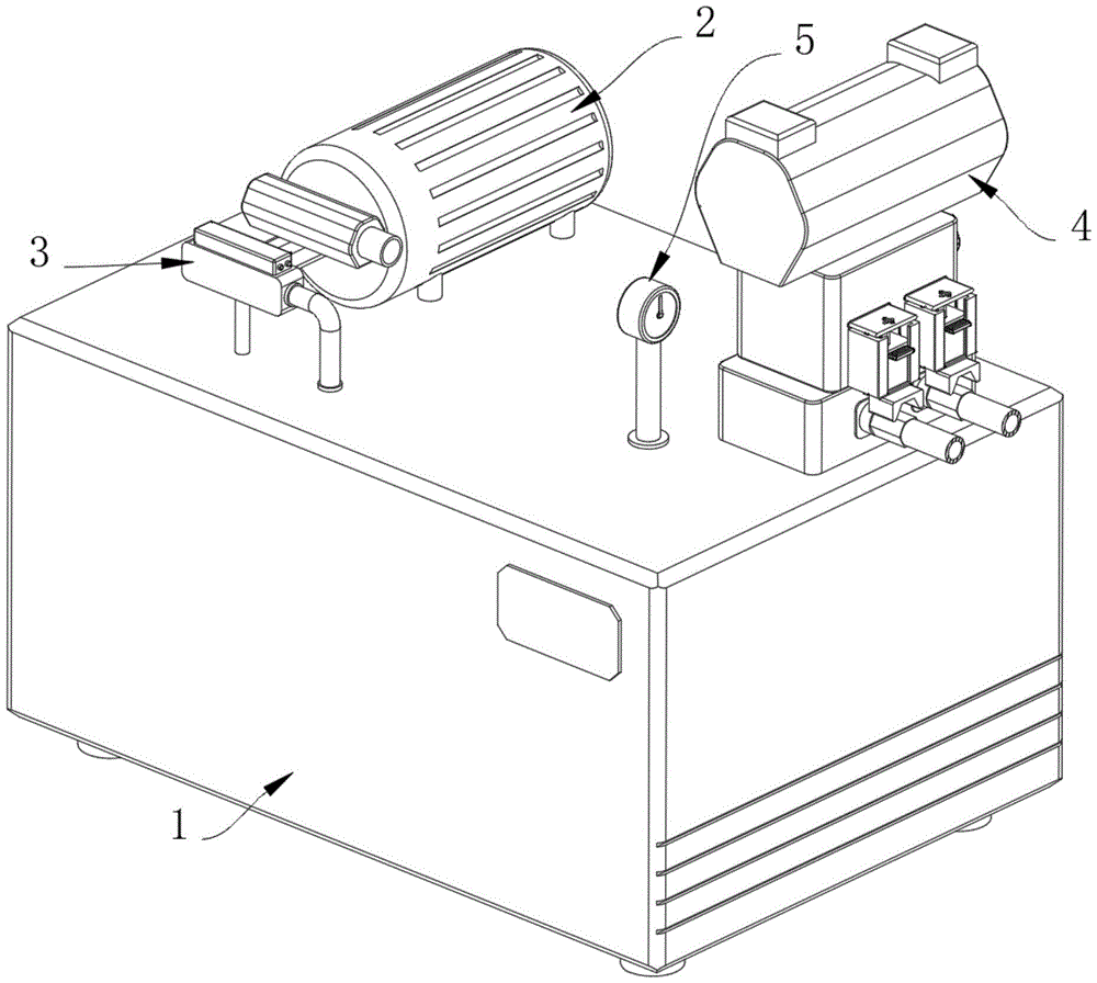
图1是本申请的立体结构示意图。Fig. 1 is a schematic diagram of the three-dimensional structure of the present application.
图2是本申请控制阀处的结构示意图。Fig. 2 is a schematic diagram of the structure of the control valve of the present application.
图3是本申请限位装置的结构示意图。Fig. 3 is a schematic structural diagram of the limiting device of the present application.
图4是本申请滑动块处的拆解结构示意图。Fig. 4 is a schematic diagram of a disassembled structure at the sliding block of the present application.
图5是本申请图2的A处结构示意图。Fig. 5 is a schematic diagram of the structure at A in Fig. 2 of the present application.
附图标记说明:Explanation of reference signs:
1、油箱;2、电机;3、液压泵;4、控制阀;5、液压表;6、控制旋钮;7、管道接头;10、油管;8、限位装置;801、L形板;802、滑动块;803、限位条;804、挡条;805、挡块;806、限位块;807、限位槽;808、限位套;809、顶板;810、弹簧;811、导向杆;9、固定装置;91、转动环;92、转动杆;93、卡块;94、卡孔;95、卡槽。1. Fuel tank; 2. Motor; 3. Hydraulic pump; 4. Control valve; 5. Hydraulic gauge; 6. Control knob; 7. Pipe joint; 10. Oil pipe; 8. Limiting device; 801. L-shaped plate; 802 , sliding block; 803, limit bar; 804, retaining bar; 805, block; 806, limit block; 807, limit groove; 808, limit sleeve; 809, top plate; 810, spring; 811, guide rod ; 9, fixing device; 91, rotating ring; 92, rotating rod; 93, clamping block; 94, clamping hole; 95, clamping slot.
具体实施方式Detailed ways
参照图1和图2所示,本实施例公开了一种防泄漏的液压站,包括油箱1,油箱1的上表面固定安装有电机2,油箱1的上表面固定安装有液压泵3,电机2的一端与液压泵3相连接,油箱1的上表面固定安装有液压表5,油箱1的上表面固定安装有控制阀4,控制阀4的一侧固定安装有两个控制旋钮6,控制阀4的表面固定安装有两个管道接头7,管道接头7内壁螺纹连接有油管10,控制阀4表面位于管道接头7上侧的位置均设有限位装置8当操作人员使用液压站根据驱动装置要求的流向、压力和流量供油时,首先可以将油管10与管道接头7相连,并完成其他安装工作,然后启动电机2,电机2向液压泵3供能,使液压泵3将油箱1内的液压油抽出,并经控制阀4输入管道,在此过程中,可有根据实际情况和液压表5的反馈,使用控制旋钮6调整液压油的流速。1 and 2, the present embodiment discloses a leak-proof hydraulic station, including a fuel tank 1, a
参照图3和图4所示,本实施例公开了限位装置8包括两个L形板801,两个L形板801的一端与控制阀4固定连接,两个L形板801的内壁滑动连接有滑动块802,两个L形板801的下端固定连接有挡条804,滑动块802远离控制阀4一面的上侧固定连接有挡块805,挡块805的一面与挡条804相卡接,滑动块802的下端固定连接有限位块806,限位块806的下端开设有限位槽807,油管10的圆弧面固定连接有限位套808,限位槽807的内壁与限位套808相卡接。达到了当操作人员使用液压站根据驱动装置要求的流向、压力和流量供油时,因设置有限位装置8,滑动块802在限位条803的约束下向下靠近,限位套808卡入限位块806上的限位槽807内,以对油管10的松动倾向进行抑制,从而避免油管10连接处因连接件松动发生液压油泄漏,而在液压站闲置,以及运输的过程中,挡条804会通过阻挡挡块805,避免滑动块802完全滑出L形板801,从而使限位装置8更加实用。3 and 4, the present embodiment discloses that the
参照图3和图4所示,本实施例公开了滑动块802的两侧均固定连接有限位条803,限位条803的表面与L形板801滑动连接。达到了在对滑动块802的滑动状态进行限位,以使限位装置8的运行更加稳定效果,控制阀4的表面固定连接有顶板809,顶板809的下表面固定连接有弹簧810,弹簧810的下端与滑动块802固定连接。达到了通过滑动快对限位块806施加一个靠近限位套808的弹力,从而使限位块806对油管10的限位更加可靠的效果。Referring to FIG. 3 and FIG. 4 , this embodiment discloses that both sides of the
参照图3和图4所示,本实施例公开了弹簧810的内部滑动连接有导向杆811,导向杆811的一端与顶板809固定连接,导向杆811的另一端滑动插入滑动块802。达到了对弹簧810的弹力方向进行限制,使其更好的驱动滑动块802,对油管10进行限位的效果,此外也能向弹簧810提供支撑,以延长弹簧810的使用寿命,挡块805的表面均匀开设有防滑凸起。达到了使操作人员更容易移动滑动块802的位置,从而更方便操作限位装置8对油管10进行限位的效果。3 and 4, the present embodiment discloses that a
参照图3和图5所示,本实施例公开了滑动块802的上表面设有固定装置9,固定装置9包括转动环91,转动环91的下端与滑动块802固定连接,转动环91的内壁转动连接有转动杆92,转动杆92的上端固定连接有卡块93,顶板809表面对应卡块93的位置开设有卡孔94,卡孔94的内壁与卡块93滑动连接,卡块93的一面与顶板809相卡接。达到了当操作人员需要拆装油管10时,可以借助固定装置9,将限位块806临时固定在靠近顶板809的位置,从而使操作人员可以更方便的安装或拆卸油管10,进而在一定程度上提升了限位装置8的易用性,顶板809的上表面开设有卡槽95,卡槽95的内壁与卡块93相卡接。达到了对卡块93的位置进行限制,从而使卡快对限位块806的临时固定更加可靠的效果。3 and 5, the present embodiment discloses that the upper surface of the sliding
工作原理为:The working principle is:
当操作人员使用液压站根据驱动装置要求的流向、压力和流量供油时,首先可以将油管10与管道接头7相连并完成其他安装工作,然后启动电机2,电机2向液压泵3供能,使液压泵3将油箱1内的液压油抽出,并经控制阀4输入管道,在此过程中,可有根据实际情况和液压表5的反馈,使用控制旋钮6调整液压油的流速,且这时弹簧810会沿导向杆811拉伸,驱动滑动块802在限位条803的约束下向下靠近,限位套808卡入限位块806上的限位槽807内,以对油管10的松动倾向进行抑制,从而避免油管10连接处因连接件松动发生液压油泄漏,而在液压站闲置,以及运输的过程中,挡条804会通过阻挡挡块805,避免滑动块802完全滑出L形板801,从而使限位装置8更加实用,此外当操作人员需要拆装油管10时,首先可以拨动挡块805,使滑动块802上移在此过程中,限位块806会与限位套808脱离接触,直至卡块93穿过顶板809上的卡孔94,然后90度旋转转动环91内的转动杆92,随后松开挡块805,卡块93卡入卡槽95,将限位块806临时固定在靠近顶板809的位置,以方便操作人员安装或拆卸油管10,当拆装完成后再次拨动挡块805,将卡块93从卡槽95内移出,并对准卡孔94,随后松开挡块805,限位块806便会向下移动,对油管10进行限位。通过设置限位装置8和固定装置9,以及可以将限位块806临时固定在靠近顶板809的位置,从而使操作人员可以更方便的安装或拆卸油管10,进而在一定程度上提升了限位装置8的易用性。When the operator uses the hydraulic station to supply oil according to the flow direction, pressure and flow required by the driving device, firstly, the
Claims (7)
Priority Applications (1)
| Application Number | Priority Date | Filing Date | Title |
|---|---|---|---|
| CN202320004441.3U CN218844744U (en) | 2023-01-03 | 2023-01-03 | A leak-proof hydraulic station |
Applications Claiming Priority (1)
| Application Number | Priority Date | Filing Date | Title |
|---|---|---|---|
| CN202320004441.3U CN218844744U (en) | 2023-01-03 | 2023-01-03 | A leak-proof hydraulic station |
Publications (1)
| Publication Number | Publication Date |
|---|---|
| CN218844744U true CN218844744U (en) | 2023-04-11 |
Family
ID=87284635
Family Applications (1)
| Application Number | Title | Priority Date | Filing Date |
|---|---|---|---|
| CN202320004441.3U Expired - Fee Related CN218844744U (en) | 2023-01-03 | 2023-01-03 | A leak-proof hydraulic station |
Country Status (1)
| Country | Link |
|---|---|
| CN (1) | CN218844744U (en) |
-
2023
- 2023-01-03 CN CN202320004441.3U patent/CN218844744U/en not_active Expired - Fee Related
Similar Documents
| Publication | Publication Date | Title |
|---|---|---|
| CN216577552U (en) | Pipeline butt joint auxiliary fixtures | |
| CN223035986U (en) | Polyethylene gas pipe plugging device | |
| CN114110193B (en) | A corrosion-resistant and pressure-resistant valve joint and its manufacturing process | |
| CN209892858U (en) | Water tap joint assembly | |
| CN210424172U (en) | Interim leaking stoppage frock | |
| CN220506076U (en) | Hydraulic water pipe connecting device for hydraulic engineering | |
| CN201043665Y (en) | Leakage stopper of petroleum pipeline | |
| CN220540549U (en) | Valve connecting component convenient for overhauling valve | |
| CN217272584U (en) | Quick-connection indoor voltage regulator | |
| CN210940520U (en) | A corrugated pipe connection tool | |
| CN222416343U (en) | Butt joint device for installation of heating power pipeline | |
| CN222669353U (en) | A glue injection type small valve plugging device | |
| CN208719672U (en) | A kind of helical delivery compact form cover board retaining mechanism | |
| CN218063937U (en) | A non-excavation repair equipment for small-diameter in-situ pulling, jacking and replacement | |
| CN221121455U (en) | Pipeline plugging device | |
| CN220699551U (en) | Multi-pipe-diameter clamping device for pipeline production | |
| CN218947295U (en) | A kind of rust removal device for the outer surface of pipeline | |
| CN217473771U (en) | A high-performance pipe iron remover that is easy to connect quickly | |
| CN221665413U (en) | Quick butt joint structure for installing pressure pipeline | |
| CN217843066U (en) | Pipeline convenient to butt joint | |
| CN211083267U (en) | Non-stop pipeline pressured open hole plugging device | |
| CN222142749U (en) | Pipeline leakage detection positioning device | |
| CN223562842U (en) | Hierarchical flow control uninstallation emulsion pump | |
| CN204450673U (en) | Hole tapping aids for fiberglass pipes | |
| CN217153490U (en) | A leakage plugging device for urban water supply network |
Legal Events
| Date | Code | Title | Description |
|---|---|---|---|
| GR01 | Patent grant | ||
| GR01 | Patent grant | ||
| CF01 | Termination of patent right due to non-payment of annual fee | ||
| CF01 | Termination of patent right due to non-payment of annual fee |
Granted publication date: 20230411 |