CN218843670U - Electromechanical installation operation platform - Google Patents
Electromechanical installation operation platform Download PDFInfo
- Publication number
- CN218843670U CN218843670U CN202223239755.6U CN202223239755U CN218843670U CN 218843670 U CN218843670 U CN 218843670U CN 202223239755 U CN202223239755 U CN 202223239755U CN 218843670 U CN218843670 U CN 218843670U
- Authority
- CN
- China
- Prior art keywords
- rod
- plate
- servo motor
- support
- base
- Prior art date
- Legal status (The legal status is an assumption and is not a legal conclusion. Google has not performed a legal analysis and makes no representation as to the accuracy of the status listed.)
- Expired - Fee Related
Links
- 238000009434 installation Methods 0.000 title claims abstract description 31
- 239000002184 metal Substances 0.000 claims description 22
- 230000002457 bidirectional effect Effects 0.000 claims description 7
- 230000005611 electricity Effects 0.000 claims 2
- 238000010586 diagram Methods 0.000 description 6
- 230000000694 effects Effects 0.000 description 2
- 238000000034 method Methods 0.000 description 2
- 229910000831 Steel Inorganic materials 0.000 description 1
- 238000004378 air conditioning Methods 0.000 description 1
- 230000009286 beneficial effect Effects 0.000 description 1
- 238000004891 communication Methods 0.000 description 1
- 238000010276 construction Methods 0.000 description 1
- 238000010616 electrical installation Methods 0.000 description 1
- 238000005516 engineering process Methods 0.000 description 1
- 230000005484 gravity Effects 0.000 description 1
- 238000011900 installation process Methods 0.000 description 1
- 238000009413 insulation Methods 0.000 description 1
- 238000004519 manufacturing process Methods 0.000 description 1
- 238000012986 modification Methods 0.000 description 1
- 230000004048 modification Effects 0.000 description 1
- 238000005057 refrigeration Methods 0.000 description 1
- 230000000630 rising effect Effects 0.000 description 1
- 239000010959 steel Substances 0.000 description 1
- 238000009423 ventilation Methods 0.000 description 1
Images


Landscapes
- Transmission Devices (AREA)
Abstract
本实用新型的机电安装操作平台属于机电安装技术领域,该装置通过升降组件带动支撑板上下移动,支撑板上下移动时的稳定性好,工作人员可直接站在支撑板上进行安装工作,操作较为方便。通过第一伺服电机带动双向丝杆转动,使两组第一滑座沿着双向丝杆做相反方向运动,两组第一滑座分别带动两组第一支撑杆运动,第一支撑杆带动支撑板沿竖直方向运动,可对支撑板的位置高度进行调节。通过第一放置板放置较重的机电器件,通过高度调节组件可对第一放置板的位置高度进行调节,便于较重的机电器件的安装工作,通过固定组件对装置进行固定,使用起来十分的方便。通过设置倾斜报警组件在装置倾斜时进行报警,提高安全性能。

The electromechanical installation and operation platform of the utility model belongs to the technical field of electromechanical installation. The device drives the support plate to move up and down through the lifting component, and the stability of the support plate when it moves up and down is good. convenient. The first servo motor drives the two-way screw to rotate, so that the two sets of first sliding seats move in opposite directions along the two-way screw. The two sets of first sliding seats drive the two sets of first support rods to move respectively, and the first support rod drives the support The board moves in the vertical direction, and the position and height of the supporting board can be adjusted. Place heavier electromechanical devices through the first placement plate, and adjust the position and height of the first placement plate through the height adjustment component, which is convenient for the installation of heavier electromechanical devices, and fix the device through the fixing component, which is very easy to use convenient. By setting the tilt alarm component to alarm when the device is tilted, the safety performance is improved.
Description
技术领域technical field
本实用新型属于机电安装技术领域,具体为一种机电安装操作平台。The utility model belongs to the technical field of electromechanical installation, in particular to an electromechanical installation operation platform.
背景技术Background technique
当今的企业大多数都具有自动化机器设备,机电安装行业因此而诞生。一般工业和公共、民用建设项目的设备、线路、管道的安装,35千伏及以下变配电站工程,非标准钢构件的制作、安装。机电安装是个工程规模比较大的工作,有些大型企业迁移,一个工程就需要花近半年来实施,而且,对于安装的技术要求,也是相当大的。工程内容包括锅炉、通风空调、制冷、电气、仪表、电机、压缩机机组和广播电影、电视播控等设备。Most of today's enterprises have automated machinery and equipment, and the electromechanical installation industry was born. Installation of equipment, lines and pipelines for general industrial and public and civil construction projects, substation projects of 35 kV and below, production and installation of non-standard steel components. Mechanical and electrical installation is a relatively large-scale project. Some large-scale enterprises relocate, and it takes nearly half a year to implement a project. Moreover, the technical requirements for installation are also quite large. The project content includes boilers, ventilation and air conditioning, refrigeration, electrical appliances, instruments, motors, compressor units, radio, film, TV broadcast control and other equipment.
在机电安装过程中需要使用一些设备进行辅助安装,如中国专利网公开号为CN215981628U公开了一种机电安装用辅助升降装置,包括底座。该机电安装用辅助升降装置,升降板内部的第一气缸带动第一活塞杆向上运动,第一活塞杆向上运动的同时带动微调板向上运动,并且升降板顶部两侧的第一活塞杆向上运动的速度相同,以保证微调板向上运动时的稳定性,同时升降板内部设置有第一固定块,微调板向上运动的同时带动第二固定块与伸缩杆向上运动,活动杆内部设置有弹簧保证伸缩杆向上运动的自由,通过弹簧可自由调节伸缩杆与活动杆的使用长度,第一固定块对活动杆一端进行固定,通过活动杆与伸缩杆对微调板上升过程中提供支撑力,进一步提高微调板的稳定性,达到升降装置具备升降后二次微调功能的效果。该申请虽然能够起到辅助升降的作用,但稳定性较为一般,且当安装位置较高时,操作人员操作较为麻烦。In the electromechanical installation process, some equipment needs to be used for auxiliary installation. For example, the Chinese Patent Network Publication No. CN215981628U discloses an auxiliary lifting device for electromechanical installation, including a base. The auxiliary lifting device for electromechanical installation, the first cylinder inside the lifting plate drives the first piston rod to move upwards, the first piston rod moves upwards and at the same time drives the fine adjustment plate to move upwards, and the first piston rods on both sides of the top of the lifting plate move upwards The speed is the same to ensure the stability of the fine-tuning plate when it moves upwards. At the same time, there is a first fixed block inside the lifting plate. When the fine-tuned plate moves upwards, it drives the second fixed block and the telescopic rod to move upwards. A spring is installed inside the movable rod to ensure Freedom of upward movement of the telescopic rod, the use length of the telescopic rod and the movable rod can be freely adjusted through the spring, the first fixed block fixes one end of the movable rod, and the movable rod and the telescopic rod provide support for the fine-tuning plate during the rising process, further improving The stability of the fine-tuning board achieves the effect that the lifting device has the function of secondary fine-tuning after lifting. Although this application can play the role of auxiliary lifting, the stability is relatively general, and when the installation position is high, the operator's operation is relatively troublesome.
实用新型内容Utility model content
本实用新型的目的在于提供一种机电安装操作平台,以解决上述背景技术中提出的问题。The purpose of this utility model is to provide an electromechanical installation and operation platform to solve the problems raised in the above-mentioned background technology.
为此,本实用新型提供一种机电安装操作平台,包括底座,所述底座的底部安装有滚轮,还包括支撑板、高度调节组件和第一放置板,所述高度调节组件包括第二伺服电机、单向丝杆和导向杆,所述第二伺服电机设置在支撑板的顶部并与控制系统电连接;所述单向丝杆竖向连接在第二伺服电机的输出端;所述导向杆竖向连接在支撑板的顶部;所述单向丝杆和所述导向杆分别穿过所述第一放置板的两侧。To this end, the utility model provides an electromechanical installation and operation platform, including a base, the bottom of the base is equipped with rollers, and also includes a support plate, a height adjustment assembly and a first placement plate, and the height adjustment assembly includes a second servo motor , a one-way screw rod and a guide rod, the second servo motor is arranged on the top of the support plate and electrically connected with the control system; the one-way screw rod is vertically connected to the output end of the second servo motor; the guide rod vertically connected to the top of the support plate; the one-way screw rod and the guide rod pass through both sides of the first placement plate respectively.
采用上述方案,通过高度调节组件可对第一放置板的位置高度进行调节,便于较重的机电器件的安装工作。通过第二伺服电机带动单向丝杆转动,第一放置板沿着单向丝杆运动,可对第一放置板的位置高度进行调节。With the above solution, the height of the first placement plate can be adjusted through the height adjustment component, which facilitates the installation of heavy electromechanical devices. The second servo motor drives the one-way screw to rotate, and the first placing plate moves along the one-way screw, so that the position and height of the first placing plate can be adjusted.
优选地,还包括夹持组件,所述夹持组件包括固定板、电动伸缩杆和夹板,所述固定板分别连接在第一放置板的顶部两侧,所述电动伸缩杆分别连接在两块固定板相对的一侧并且所述电动伸缩杆与控制系统电连接,所述夹板分别连接在电动伸缩杆远离固定板的一端。Preferably, a clamping assembly is also included, the clamping assembly includes a fixed plate, an electric telescopic rod and a splint, the fixed plate is respectively connected to both sides of the top of the first placement plate, and the electric telescopic rod is respectively connected to two The opposite side of the fixed plate and the electric telescopic rod are electrically connected to the control system, and the splints are respectively connected to one end of the electric telescopic rod away from the fixed plate.
采用上述方案,通过电动伸缩杆带动夹板运动,通过夹板对第一放置板上的机电器件进行夹持固定。With the above scheme, the splint is driven to move by the electric telescopic rod, and the electromechanical device on the first placement plate is clamped and fixed by the splint.
优选地,每块固定板的一侧连接有两个电动伸缩杆。Preferably, two electric telescopic rods are connected to one side of each fixing plate.
优选地,还包括升降组件,所述升降组件连接在底座的顶部,所述支撑板连接在升降组件的顶部,所述升降组件包括:Preferably, a lifting assembly is also included, the lifting assembly is connected to the top of the base, the support plate is connected to the top of the lifting assembly, and the lifting assembly includes:
第一伺服电机,安装在底座的顶部,所述第一伺服电机与安装在支撑板顶部的控制系统电连接;The first servo motor is installed on the top of the base, and the first servo motor is electrically connected to the control system installed on the top of the support plate;
双向丝杆,水平连接在第一伺服电机的输出端;A bidirectional screw rod is horizontally connected to the output end of the first servo motor;
第一滑座,分别螺接在双向丝杆的两端,所述第一滑座的底部与底座的顶部滑动接触;The first sliding seat is respectively screwed to the two ends of the two-way screw rod, and the bottom of the first sliding seat is in sliding contact with the top of the base;
第一支撑杆,分别连接在两个第一滑座的顶部与支撑板的底部之间,并且第一支撑杆的一端与第一滑座的顶部铰接连接,另一端与支撑板的底部铰接连接。The first support rod is respectively connected between the tops of the two first slide seats and the bottom of the support plate, and one end of the first support rod is hingedly connected with the top of the first slide seat, and the other end is hingedly connected with the bottom of the support plate .
采用上述方案,通过升降组件带动支撑板上下移动,支撑板上下移动时的稳定性好,工作人员可直接站在支撑板上进行安装工作,操作较为方便。通过第一伺服电机带动双向丝杆转动,使两组第一滑座沿着双向丝杆做相反方向运动,两组第一滑座分别带动两组第一支撑杆运动,第一支撑杆带动支撑板沿竖直方向运动,可对支撑板的位置高度进行调节。With the above scheme, the lifting component drives the support plate to move up and down, the stability of the support plate is good when it moves up and down, and the staff can directly stand on the support plate to carry out installation work, and the operation is more convenient. The first servo motor drives the two-way screw to rotate, so that the two sets of first sliding seats move in opposite directions along the two-way screw. The two sets of first sliding seats respectively drive the two sets of first support rods to move, and the first support rods drive the support The board moves in the vertical direction, and the position and height of the supporting board can be adjusted.
优选地,所述升降组件还包括:Preferably, the lift assembly also includes:
连接杆,连接在第一滑座的两侧;connecting rods, connected to both sides of the first sliding seat;
第二滑座,连接在连接杆远离第一滑座的一端;The second sliding seat is connected to the end of the connecting rod away from the first sliding seat;
第二支撑杆,分别连接在第二滑座的顶部与支撑板的底部之间,并且第二支撑杆的一端与第二滑座的顶部铰接连接,另一端与支撑板的底部铰接连接。The second support rod is respectively connected between the top of the second slide seat and the bottom of the support plate, and one end of the second support rod is hingedly connected with the top of the second slide seat, and the other end is hingedly connected with the bottom of the support plate.
采用上述方案,第一滑座通过连接杆带动第二滑座运动,第二滑座带动第二支撑杆运动,第二支撑杆带动支撑板沿竖直方向运动,进一步提高支撑板运动时的稳定性。With the above scheme, the first sliding seat drives the second sliding seat to move through the connecting rod, the second sliding seat drives the second support rod to move, and the second support rod drives the support plate to move in the vertical direction, further improving the stability of the support plate during movement sex.
优选地,双向丝杆同侧的第二滑座之间穿设有一根光杆,所述第二滑座与光杆滑动连接,所述光杆的两端连接有限位板,所述限位板与底座的顶部连接。通过限位板可对第二滑座起到限位作用。Preferably, a polished rod is threaded between the second sliding seat on the same side of the bidirectional screw rod, the second sliding seat is slidably connected to the polished rod, the two ends of the polished rod are connected to a limiting plate, and the limiting plate is connected to the base top connection. The second sliding seat can be limited by the limiting plate.
优选地,所述双向丝杆远离第一伺服电机的一端连接有限位块。通过限位块对第一滑座起到限位作用。Preferably, the end of the bidirectional screw rod away from the first servo motor is connected with a limit block. The first sliding seat is limited by the limit block.
优选地,还包括固定组件,所述固定组件包括连接板、螺纹杆、摩擦块和旋拧块,所述连接板连接在底座的侧部,所述螺纹杆竖向穿过所述连接板,所述摩擦块连接在所述螺纹杆的底端,所述旋拧块连接在螺纹杆的顶端。Preferably, a fixing assembly is also included, the fixing assembly includes a connecting plate, a threaded rod, a friction block and a screwing block, the connecting plate is connected to the side of the base, the threaded rod vertically passes through the connecting plate, The friction block is connected to the bottom end of the threaded rod, and the screw block is connected to the top end of the threaded rod.
采用上述方案,通过旋拧块转动螺纹杆,螺纹杆带动摩擦块向下运动,使摩擦块与地面摩擦接触,对装置进行固定。With the above scheme, the threaded rod is rotated by the screw block, and the threaded rod drives the friction block to move downward, so that the friction block is in frictional contact with the ground, and the device is fixed.
优选地,还包括倾斜报警组件,所述倾斜报警组件安装在支撑板的底部,包括绝缘外筒、套设在倾斜报警组件内的金属套筒、铰接连接在绝缘外筒内顶壁的金属棒、以及安装在绝缘外筒内底壁的电池和报警器,所述电池的正极与报警器、金属套筒之间电连接,所述电池的负极与金属棒之间电连接,所述支撑板倾斜时,金属棒可与金属套筒内壁相接触。Preferably, a tilt alarm assembly is also included, the tilt alarm assembly is installed at the bottom of the support plate, including an insulating outer cylinder, a metal sleeve sleeved in the tilt alarm assembly, and a metal rod hingedly connected to the inner top wall of the insulating outer cylinder , and a battery and an alarm installed on the inner bottom wall of the insulating outer cylinder, the positive pole of the battery is electrically connected to the alarm and the metal sleeve, the negative pole of the battery is electrically connected to the metal rod, and the support plate When tilted, the metal rod can be in contact with the inner wall of the metal sleeve.
采用上述方案,可以在装置倾斜时进行报警,提高安全性能。优选地,所述支撑板的顶部竖向连接有固定杆,所述固定杆的顶部连接有第二放置板,所述第二放置板的顶部开设有放置槽。By adopting the scheme, an alarm can be given when the device is tilted, thereby improving safety performance. Preferably, a fixing rod is vertically connected to the top of the support plate, a second placement board is connected to the top of the fixing rod, and a placement slot is opened on the top of the second placement board.
采用上述方案,可将需要使用到的一些较小的器件放置于第二放置板顶部的放置槽内,便于较小的器件的后续的使用。By adopting the above solution, some smaller devices that need to be used can be placed in the placement grooves on the top of the second placement plate, which facilitates the subsequent use of smaller devices.
与现有技术相比,本实用新型的特点和有益效果为:Compared with the prior art, the features and beneficial effects of the utility model are:
(1)本实用新型通过升降组件带动支撑板上下移动,支撑板上下移动时的稳定性好,工作人员可直接站在支撑板上进行安装工作,操作较为方便,通过第一放置板放置较重的机电器件,通过高度调节组件可对第一放置板的位置高度进行调节,便于较重的机电器件的安装工作,通过固定组件对装置进行固定,使用起来十分的方便。通过设置倾斜报警组件在装置倾斜时进行报警,提高安全性能。(1) The utility model drives the support plate to move up and down through the lifting assembly. The stability of the support plate when it moves up and down is good. The staff can directly stand on the support plate for installation work. The operation is more convenient, and it is heavier to place through the first placement plate For electromechanical devices, the position and height of the first placement plate can be adjusted through the height adjustment component, which is convenient for the installation of heavy electromechanical devices, and the device is fixed through the fixing component, which is very convenient to use. By setting the tilt alarm component to alarm when the device is tilted, the safety performance is improved.
(2)本实用新型通过第一伺服电机带动双向丝杆转动,使两组第一滑座沿着双向丝杆做相反方向运动,两组第一滑座分别带动两组第一支撑杆运动,第一支撑杆带动支撑板沿竖直方向运动,可对支撑板的位置高度进行调节。第一滑座通过连接杆带动第二滑座运动,第二滑座带动第二支撑杆运动,第二支撑杆带动支撑板沿竖直方向运动,进一步提高支撑板运动时的稳定性。第二滑座沿光杆滑动,更进一步提高支撑板运动时的稳定性。(2) The utility model drives the two-way screw rod to rotate through the first servo motor, so that the two groups of first sliding seats move in opposite directions along the two-way screw rod, and the two groups of first sliding seats respectively drive the two groups of first support rods to move, The first support rod drives the support plate to move in the vertical direction, and the position and height of the support plate can be adjusted. The first sliding seat drives the second sliding seat to move through the connecting rod, the second sliding seat drives the second supporting rod to move, and the second supporting rod drives the supporting plate to move in the vertical direction, further improving the stability of the supporting plate when it moves. The second sliding seat slides along the polished rod, further improving the stability of the support plate when it moves.
附图说明Description of drawings
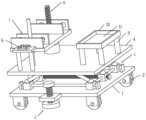
图1为本实用新型第一视角结构示意图;Fig. 1 is a structural schematic diagram of the first viewing angle of the utility model;
图2为本实用新型第二视角结构示意图;Fig. 2 is a schematic structural diagram of the second viewing angle of the utility model;
图3为本实用新型第三视角结构示意图;Fig. 3 is a structural schematic diagram of a third viewing angle of the utility model;
图4为本实用新型第四视角结构示意图;Fig. 4 is a schematic structural diagram of a fourth viewing angle of the utility model;
图5为本实用新型第五视角结构示意图;Fig. 5 is a structural schematic diagram of a fifth viewing angle of the utility model;
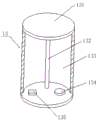
图6为倾斜报警组件的示意图。Figure 6 is a schematic diagram of a tilt alarm assembly.
附图标注:1-底座、2-滚轮、3-升降组件、31-第一伺服电机、310-限位块、32-双向丝杆、33-第一滑座、34-连接杆、35-第二滑座、36-第二支撑杆、37-限位板、38-光杆、39-第一支撑杆、4-支撑板、5-固定组件、51-连接板、52-摩擦块、53-螺纹杆、54-旋拧块、6-控制系统、7-夹持组件、71-固定板、72-电动伸缩杆、73-夹板、8-高度调节组件、81-第二伺服电机、82-单向丝杆、83-导向杆、9-固定杆、10-第二放置板、11-放置槽、12-第一放置板、13-倾斜报警组件、131-绝缘外筒、132-金属棒、133-金属套筒、134-报警器、135-电池。Drawings: 1-base, 2-roller, 3-lifting assembly, 31-first servo motor, 310-limit block, 32-two-way screw, 33-first sliding seat, 34-connecting rod, 35- The second sliding seat, 36-second support rod, 37-limiting plate, 38-polished rod, 39-first support rod, 4-support plate, 5-fixed assembly, 51-connecting plate, 52-friction block, 53 -threaded rod, 54-screwing block, 6-control system, 7-clamping assembly, 71-fixing plate, 72-electric telescopic rod, 73-splint, 8-height adjustment assembly, 81-second servo motor, 82 -One-way screw, 83-guide rod, 9-fixing rod, 10-second placement plate, 11-placement slot, 12-first placement plate, 13-tilt alarm assembly, 131-insulation outer cylinder, 132-metal Rod, 133-metal sleeve, 134-alarm, 135-battery.
具体实施方式Detailed ways
为使本实用新型实现的技术手段、创新特征、达成目的与功效易于明白了解,下面对本实用新型进一步说明。In order to make the technical means, innovative features, goals and effects achieved by the utility model easy to understand, the utility model will be further described below.
在此记载的实施例为本实用新型的特定的具体实施方式,用于说明本实用新型的构思,均是解释性和示例性的,不应解释为对本实用新型实施方式及本实用新型范围的限制。除在此记载的实施例外,本领域技术人员还能够基于本申请权利要求书和说明书所公开的内容采用显而易见的其它技术方案,这些技术方案包括采用对在此记载的实施例的做出任何显而易见的替换和修改的技术方案。The embodiments described here are specific specific implementations of the present utility model, and are used to illustrate the concept of the present utility model. They are all explanatory and exemplary, and should not be construed as limitations on the implementation of the present utility model and the scope of the present utility model. limit. In addition to the embodiments described here, those skilled in the art can also adopt other obvious technical solutions based on the claims of the application and the contents disclosed in the description, and these technical solutions include adopting any obvious changes made to the embodiments described here. Replacement and modified technical solutions.
在本实用新型的描述中,需要说明的是,术语“上”、“下”、“内”、“外”“前端”、“后端”、“两端”、“一端”、“另一端”等指示的方位或位置关系为基于附图所示的方位或位置关系,仅是为了便于描述本实用新型和简化描述,而不是指示或暗示所指的装置或元件必须具有特定的方位、以特定的方位构造和操作,因此不能理解为对本实用新型的限制。此外,术语“第一”、“第二”仅用于描述目的,而不能理解为指示或暗示相对重要性。In the description of the present utility model, it should be noted that the terms "upper", "lower", "inner", "outer", "front end", "rear end", "both ends", "one end", "another end" The orientation or positional relationship indicated by ", etc. is based on the orientation or positional relationship shown in the drawings, which is only for the convenience of describing the utility model and simplifying the description, rather than indicating or implying that the device or element referred to must have a specific orientation, so as to Specific orientation configurations and operations, therefore, should not be construed as limitations on the invention. In addition, the terms "first" and "second" are used for descriptive purposes only, and should not be understood as indicating or implying relative importance.
在本实用新型的描述中,需要说明的是,除非另有明确的规定和限定,术语“安装”、“设置有”、“连接”等,应做广义理解,例如“连接”,可以是固定连接,也可以是可拆卸连接,或一体地连接;可以是机械连接,也可以是电连接;可以是直接相连,也可以通过中间媒介间接相连,可以是两个元件内部的连通。对于本领域的普通技术人员而言,可以具体情况理解上述术语在本实用新型中的具体含义。In the description of the present utility model, it should be noted that, unless otherwise specified and limited, the terms "installed", "set with", "connected", etc. should be understood in a broad sense, such as "connected", which can be a fixed The connection can also be a detachable connection or an integral connection; it can be a mechanical connection or an electrical connection; it can be a direct connection or an indirect connection through an intermediary, and it can be the internal communication of two components. Those of ordinary skill in the art can understand the specific meanings of the above terms in the present utility model in specific situations.
如图1-6所示,本实用新型提供一种机电安装操作平台,包括底座1,底座1的底部安装有滚轮2,还包括升降组件3和支撑板4,升降组件3连接在底座1的顶部,支撑板4连接在升降组件3的顶部,升降组件3包括第一伺服电机31、双向丝杆32、第一滑座33和第一支撑杆39。第一伺服电机31安装在底座1的顶部,第一伺服电机31与安装在支撑板4顶部的控制系统6电连接。双向丝杆32水平连接在第一伺服电机31的输出端。第一滑座33分别螺接在双向丝杆32的两端,第一滑座33的底部与底座1的顶部滑动接触。双向丝杆32远离第一伺服电机31的一端连接有限位块310。第一支撑杆39分别连接在两个第一滑座33的顶部与支撑板4的底部之间,并且第一支撑杆39的一端与第一滑座33的顶部铰接连接,另一端与支撑板4的底部铰接连接。As shown in Figures 1-6, the utility model provides an electromechanical installation and operation platform, including a
为了进一步提高支撑板4升降时候的稳定性,升降组件3还包括连接杆34、第二滑座35和第二支撑杆36。连接杆34连接在第一滑座33的两侧。第二滑座35连接在连接杆34远离第一滑座33的一端。第二支撑杆36分别连接在第二滑座35的顶部与支撑板4的底部之间,并且第二支撑杆36的一端与第二滑座35的顶部铰接连接,另一端与支撑板4的底部铰接连接。In order to further improve the stability when the
为了更进一步提高支撑板4升降时候的稳定性,双向丝杆32同侧的第二滑座35之间穿设有一根光杆38,第二滑座35与光杆38滑动连接,光杆38的两端连接有限位板37,限位板37与底座1的顶部连接。In order to further improve the stability when the
还包括高度调节组件8和第一放置板12,高度调节组件8包括第二伺服电机81、单向丝杆82和导向杆83,第二伺服电机81设置在支撑板4的顶部并与控制系统6电连接;单向丝杆82竖向连接在第二伺服电机81的输出端;导向杆83竖向连接在支撑板4的顶部;单向丝杆82和导向杆83分别穿过第一放置板12的两侧。Also include
为了便于对机电器件进行夹持固定,本实用新型还设置了夹持组件7,夹持组件7包括固定板71、电动伸缩杆72和夹板73,固定板71分别连接在第一放置板12的顶部两侧,电动伸缩杆72分别连接在两块固定板71相对的一侧并且电动伸缩杆72与控制系统6电连接,夹板73分别连接在电动伸缩杆72远离固定板71的一端。在一个更加优选的实施例中,每块固定板71的一侧连接有两个电动伸缩杆72。In order to facilitate the clamping and fixing of the electromechanical devices, the utility model is also provided with a clamping
为了便于对本实用新型的机电安装工程用多功能操作装置进行固定,本实用新型还设置了固定组件5,固定组件5包括连接板51、螺纹杆53、摩擦块52和旋拧块54,连接板51连接在底座1的侧部,螺纹杆53竖向穿过连接板51,摩擦块52连接在螺纹杆53的底端,旋拧块54连接在螺纹杆53的顶端。In order to fix the multifunctional operating device for electromechanical installation engineering of the present utility model, the utility model is also provided with a fixed
为了提高装置的安全性能,本实用新型还在支撑板4的底部安装倾斜报警组件13,如图6所示,倾斜报警组件13安装在支撑板4的底部,包括中空的绝缘外筒131、套设在倾斜报警组件13内的金属套筒133、铰接连接在绝缘外筒131内顶壁的金属棒132、以及安装在绝缘外筒131内底壁的电池135和报警器134,电池135的正极与报警器134、金属套筒133之间电连接,电池135的负极与金属棒132之间电连接,支撑板4倾斜时,由于重力作用,金属棒132会随着支撑板4倾斜并与金属套筒133内壁相接触,此时电池135、报警器134、金属套筒133和金属棒132之间形成闭合回路,报警器134通电启动,开始报警。In order to improve the safety performance of the device, the utility model also installs a
为了方便收纳和放置较小的器件,本实用新型还在支撑板4的顶部竖向连接有固定杆9,固定杆9的顶部连接有第二放置板10,第二放置板10的顶部开设有放置槽11。In order to accommodate and place smaller devices conveniently, the utility model is also vertically connected with a fixed
以上的实施例仅仅是对本实用新型的优选实施方式进行描述,并非对本实用新型的范围进行限定,在不脱离本实用新型设计精神的前提下,本领域普通技术人员对本实用新型的技术方案做出的各种变形和改进,均应落入本实用新型权利要求书确定的保护范围内。The above embodiment is only a description of the preferred implementation of the present utility model, not to limit the scope of the present utility model. All modifications and improvements should fall within the scope of protection determined by the claims of the utility model.
Claims (9)
Priority Applications (1)
| Application Number | Priority Date | Filing Date | Title |
|---|---|---|---|
| CN202223239755.6U CN218843670U (en) | 2022-12-05 | 2022-12-05 | Electromechanical installation operation platform |
Applications Claiming Priority (1)
| Application Number | Priority Date | Filing Date | Title |
|---|---|---|---|
| CN202223239755.6U CN218843670U (en) | 2022-12-05 | 2022-12-05 | Electromechanical installation operation platform |
Publications (1)
| Publication Number | Publication Date |
|---|---|
| CN218843670U true CN218843670U (en) | 2023-04-11 |
Family
ID=87292081
Family Applications (1)
| Application Number | Title | Priority Date | Filing Date |
|---|---|---|---|
| CN202223239755.6U Expired - Fee Related CN218843670U (en) | 2022-12-05 | 2022-12-05 | Electromechanical installation operation platform |
Country Status (1)
| Country | Link |
|---|---|
| CN (1) | CN218843670U (en) |
-
2022
- 2022-12-05 CN CN202223239755.6U patent/CN218843670U/en not_active Expired - Fee Related
Similar Documents
| Publication | Publication Date | Title |
|---|---|---|
| CN115650104A (en) | Multifunctional operation device capable of stably lifting and used for electromechanical installation engineering | |
| CN219851941U (en) | Turning device is used in forging processing | |
| CN116599362B (en) | Photovoltaic inverter capable of carrying out solar charging | |
| CN217535330U (en) | Lifting device for mounting electromechanical engineering pipeline | |
| CN216552881U (en) | Installation device convenient to fixed stay people's air defense door | |
| CN212444924U (en) | Adjustable fixture for processing air conditioner liquid separator | |
| CN210065051U (en) | Automobile lifter device | |
| CN211959114U (en) | A solar photovoltaic support frame | |
| CN212208716U (en) | A small PLC-controlled refrigeration system teaching equipment | |
| CN211404229U (en) | Power supply equipment capable of reducing line loss and voltage conversion loss | |
| CN211493694U (en) | A photovoltaic power generation device for new energy vehicles | |
| CN222880548U (en) | Installation device for air conditioning construction | |
| CN218511159U (en) | Energy efficiency lifting device for air conditioner of machine room | |
| CN220233990U (en) | Cable installation regulating frame for electric power construction | |
| CN111446824B (en) | Explosion-proof motor mounting device | |
| CN222422914U (en) | Power distribution cabinet moving base | |
| CN216521305U (en) | Intelligent lighting device that construction can be regulated and control with basement is built in room | |
| CN217933378U (en) | Transformer with adjustable mounting bracket | |
| CN223522221U (en) | Building power equipment installation adjusting device | |
| CN223552997U (en) | A busbar connector fixing device | |
| CN223583536U (en) | A new type of reinforced mounting base for relays and distribution cabinets | |
| CN221651277U (en) | Installing support and transformer installation mechanism | |
| CN219697335U (en) | Wall-hanging charger convenient to fix at wall | |
| CN220932037U (en) | Air conditioner installation level | |
| CN216290177U (en) | Microcomputer protection device convenient to installation |
Legal Events
| Date | Code | Title | Description |
|---|---|---|---|
| GR01 | Patent grant | ||
| GR01 | Patent grant | ||
| CF01 | Termination of patent right due to non-payment of annual fee | ||
| CF01 | Termination of patent right due to non-payment of annual fee |
Granted publication date: 20230411 |