CN218829728U - Multi-angle adjustable photovoltaic module - Google Patents
Multi-angle adjustable photovoltaic module Download PDFInfo
- Publication number
- CN218829728U CN218829728U CN202222481488.7U CN202222481488U CN218829728U CN 218829728 U CN218829728 U CN 218829728U CN 202222481488 U CN202222481488 U CN 202222481488U CN 218829728 U CN218829728 U CN 218829728U
- Authority
- CN
- China
- Prior art keywords
- pillar
- photovoltaic
- angle adjustable
- photovoltaic module
- photovoltaic board
- Prior art date
- Legal status (The legal status is an assumption and is not a legal conclusion. Google has not performed a legal analysis and makes no representation as to the accuracy of the status listed.)
- Active
Links
Images

Classifications
-
- Y—GENERAL TAGGING OF NEW TECHNOLOGICAL DEVELOPMENTS; GENERAL TAGGING OF CROSS-SECTIONAL TECHNOLOGIES SPANNING OVER SEVERAL SECTIONS OF THE IPC; TECHNICAL SUBJECTS COVERED BY FORMER USPC CROSS-REFERENCE ART COLLECTIONS [XRACs] AND DIGESTS
- Y02—TECHNOLOGIES OR APPLICATIONS FOR MITIGATION OR ADAPTATION AGAINST CLIMATE CHANGE
- Y02E—REDUCTION OF GREENHOUSE GAS [GHG] EMISSIONS, RELATED TO ENERGY GENERATION, TRANSMISSION OR DISTRIBUTION
- Y02E10/00—Energy generation through renewable energy sources
- Y02E10/50—Photovoltaic [PV] energy
Landscapes
- Photovoltaic Devices (AREA)
Abstract
The utility model relates to a multi-angle adjustable photovoltaic module; including the base, its characterized in that: the upper portion of base is provided with the lower pillar that is used for playing the supporting role rather than bolted connection, be provided with directly over the pillar down and be used for playing the last pillar of rotation effect, it is provided with the circumference drive assembly who is used for providing the circumference rotation effect to go up between pillar and the lower pillar, the top of going up the pillar is provided with the photovoltaic board that is used for photoelectric conversion effect, one side of going up the pillar is provided with the space upset subassembly that is used for driving the photovoltaic board and takes place the upset in the space, it is provided with the carrier assembly who is used for bearing the weight of photovoltaic board to go up between pillar and the photovoltaic board. The utility model provides a problem of the comparatively sufficient illumination energy of unable timely efficient receipt.
Description
Technical Field
The utility model relates to the field of photovoltaic technology, especially, relate to an adjustable photovoltaic module of multi-angle.
Background
In the prior art, CN207926513U discloses a novel solar photovoltaic module device, which has the technical scheme that: a novel solar photovoltaic module device comprises a solar panel connecting assembly, a solar panel frame and a solar panel frame connecting assembly, wherein a solar panel is installed inside the solar panel frame, the solar panel connecting assembly is arranged at the bottom of the solar panel, the solar panel connecting assembly is installed on the inner side of the bottom of the solar panel frame, the solar panel frame connecting assembly is arranged on one side of the solar panel frame, the bottom of the solar panel frame connecting assembly is connected with a hydraulic telescopic rod, an installation base is installed at the bottom of the hydraulic telescopic rod, and a plurality of expansion screws are installed on the installation base; the solar panel connecting assembly comprises a spring supporting block, a limiting baffle and a spring, wherein the spring supporting block is installed on the inner side of the bottom of the solar panel frame, the spring is installed above the spring supporting block, the limiting baffle is arranged above the spring, and the limiting baffle is installed at the bottom of the solar panel; the solar panel frame connecting assembly comprises a connecting seat, limiting blocks, wood pins and limiting grooves, wherein the connecting seat is installed on one side of a solar panel frame, the two sides of the connecting seat are provided with the mutually symmetrical limiting blocks, the bottom of the connecting seat is provided with the limiting grooves, the wood pins are connected between the limiting blocks and the limiting grooves, and the limiting grooves are installed on the top of the hydraulic telescopic rod;
the technical scheme has the advantages that: the solar panel connecting assembly and the solar panel frame connecting assembly are designed, so that the solar panel and the plate frame can be quickly connected;
the technical scheme has the following defects: although the connection mode between solar panel and the sheet frame has been simplified, its orientation in the space is fixed mode, can not carry out angle modulation, causes its unable timely efficient comparatively sufficient illumination energy of receipt.
SUMMERY OF THE UTILITY MODEL
The utility model aims to solve the problem that although the connected mode between solar panel and the sheet frame has been simplified among the prior art, its orientation in the space is fixed mode, can not carry out angle modulation, causes the problem of its unable timely efficient receipt comparatively sufficient illumination energy.
In order to solve the technical problem, the utility model provides an including the base, its characterized in that: the upper portion of base is provided with the lower pillar that is used for playing the supporting role rather than bolted connection, be provided with directly over the pillar down and be used for playing the last pillar that rotates the effect, it is provided with the circumference drive assembly who is used for providing the circumferential direction effect to rotate between pillar and the lower pillar to go up, the top of going up the pillar is provided with the photovoltaic board that is used for photoelectric conversion effect, one side of going up the pillar is provided with the space upset subassembly that is used for driving the photovoltaic board and takes place the upset in the space, it is provided with the carrier assembly who is used for bearing the weight of photovoltaic board to go up between pillar and the photovoltaic board.
Because the utility model discloses circumference drive assembly, space upset subassembly and carrier assembly have been designed on base upper portion, consequently can drive the photovoltaic board and rotate and can also provide stable supporting role inside the space, solved among the prior art though simplified the connected mode between solar panel and the sheet frame, but its orientation in the space is fixed mode, can not carry out angle modulation, causes the problem that it can't be timely efficient and receive comparatively sufficient illumination energy.
Drawings
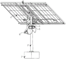
FIG. 1 is a schematic diagram of the front side of the overall structure of a multi-angle adjustable photovoltaic module.
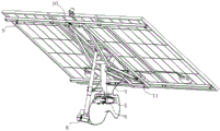
FIG. 2 is a schematic view of the back of the overall structure of a multi-angle adjustable photovoltaic module.
Fig. 3 is a schematic diagram of a space overturning assembly and a bearing assembly of a multi-angle adjustable photovoltaic assembly.
In the figure: 1. a base; 2. a lower base pillar; 3. an upper base pillar; 4. a photovoltaic panel; 5. a speed reducer; 6. a motor; 7. a triangular bracket; 8. gas bracing; 9. a cross brace; 10. a square bracket; 11. a triangular bracket; 12. an electrical box; 13. a light-sensitive sensor.
Detailed Description
The utility model relates to an adjustable photovoltaic module of multi-angle, this photovoltaic module is including being used for the base of supporting role as shown in fig. 1-3, the upper portion of base is provided with the lower pillar that is used for playing the supporting role rather than bolted connection, be provided with directly over the pillar down and be used for playing the last pillar of rotation effect, it is provided with the circumference drive assembly who is used for providing the circumferential direction effect to go up between pillar and the lower pillar, the top of going up the pillar is provided with the photovoltaic board that is used for photoelectric conversion effect, one side of going up the pillar is provided with the space upset subassembly that is used for driving the photovoltaic board and takes place the upset in the space, it is provided with the carrier assembly who is used for bearing the photovoltaic board to go up between pillar and the photovoltaic board.
As shown in fig. 1-3, the circumferential driving assembly includes a speed reducer disposed between the upper base pillar and the lower base pillar for driving the upper base pillar to rotate circumferentially, and a motor connected to a bolt of the speed reducer for driving the speed reducer to rotate is disposed on one side of the speed reducer.
As shown in fig. 1-3, the space overturning assembly comprises a triangular bracket which is arranged on one side of the upper foundation column and is fixedly connected with the upper foundation column for supporting, and the upper part of the triangular bracket is provided with a gas support which is connected with a rotating shaft of the triangular bracket for supporting the photovoltaic panel to overturn.
As shown in fig. 1-3, the bearing component comprises a cross brace which is arranged at the back of the photovoltaic panels and is fixedly connected with the photovoltaic panels for supporting, a square support which is connected with a bolt of the cross brace and is used for supporting is arranged at the middle position of the upper portion of the cross brace, triangular supports which are used for extending, supporting and stabilizing are symmetrically arranged at the upper portion of the square support, and the triangular supports are connected with the upper foundation columns through rotating shafts.
As shown in fig. 1-3, an electric box connected with the back of the photovoltaic panel by bolts for transmitting electric energy converted from the photovoltaic panel is arranged at the back of the photovoltaic panel, and a photosensitive sensor connected with the bolts for monitoring the illumination intensity in the space is arranged at the top edge position of the photovoltaic panel arranged in the middle at the upper part of the cross brace, and is used for controlling the motor and the pneumatic support to drive the photovoltaic panel to align to the optimal lighting position for performing photoelectric conversion operation.
The user is using the utility model discloses during the photovoltaic module who makes, through the comparatively sufficient place of illumination intensity in the photosensor monitoring space, the electric energy control motor function through coming from the electricity box immediately, thereby the motor takes place to rotate through driving the foundation pillar in the drive of drive speed reducer operation, and along with the rotation of last foundation pillar just can drive carrier assembly and photovoltaic board and carry out the rotation in the space and operate, and the gas props then drives carrier assembly and photovoltaic board and carries out the upset operation in the space, and be provided with the stull that is used for can fixing polylith photovoltaic board at the back of photovoltaic board, and still assist square support and the A-frame of strengthening the supporting role.
It is to be understood that the present invention has been described with reference to certain embodiments, and that various changes or equivalents may be substituted for elements thereof by those skilled in the art without departing from the spirit and scope of the invention. In addition, many modifications may be made to adapt a particular situation or material to the teachings of the invention without departing from the essential scope thereof. Therefore, the present invention is not limited to the specific embodiments disclosed herein, and all embodiments falling within the scope of the claims of the present application are intended to be covered by the present invention.
Claims (5)
1. A multi-angle adjustable photovoltaic module comprises a base (1), and is characterized in that: the upper portion of base (1) is provided with and is used for playing supporting role's lower pillar (2) rather than bolted connection, be provided with directly over pillar (2) down and be used for playing rotation effect last pillar (3), it is provided with the circumference drive assembly who is used for providing the circumference rotation effect to go up between pillar (3) and lower pillar (2), the top of going up pillar (3) is provided with photovoltaic board (4) that are used for photoelectric conversion effect, one side of going up pillar (3) is provided with the space upset subassembly that is used for driving photovoltaic board (4) to take place the upset in the space, it is provided with the carrier assembly who is used for bearing photovoltaic board (4) to go up between pillar (3) and photovoltaic board (4).
2. The multi-angle adjustable photovoltaic module of claim 1, wherein: the circumferential driving assembly comprises a speed reducer (5) arranged between the upper foundation column (3) and the lower foundation column (2), and a motor (6) connected with the speed reducer through a bolt is arranged on one side of the speed reducer (5).
3. The multi-angle adjustable photovoltaic module of claim 1, wherein: the space overturning assembly comprises a triangular bracket (7) which is arranged on one side of the upper foundation column (3) and is fixedly connected with the upper foundation column, and an air support (8) connected with a rotating shaft of the triangular bracket (7) is arranged on the upper portion of the triangular bracket.
4. The multi-angle adjustable photovoltaic module of claim 1, wherein: the bearing assembly comprises cross braces (9) which are arranged on the backs of the photovoltaic panels (4) and fixedly connected with the photovoltaic panels, square supports (10) which are connected with bolts are arranged on the upper portions of the cross braces (9) in the middle, triangular supports (11) are symmetrically arranged on the upper portions of the square supports (10), and the triangular supports (11) are connected with the upper foundation columns (3) through rotating shafts.
5. The multi-angle adjustable photovoltaic module of claim 4, wherein: an electric box (12) connected with the photovoltaic panel through bolts is arranged on the back of the photovoltaic panel (4), and a photosensitive sensor (13) connected with the bolts is arranged at the top edge of the photovoltaic panel (4) arranged in the middle of the upper part of the cross brace (9).
Priority Applications (1)
| Application Number | Priority Date | Filing Date | Title |
|---|---|---|---|
| CN202222481488.7U CN218829728U (en) | 2022-09-20 | 2022-09-20 | Multi-angle adjustable photovoltaic module |
Applications Claiming Priority (1)
| Application Number | Priority Date | Filing Date | Title |
|---|---|---|---|
| CN202222481488.7U CN218829728U (en) | 2022-09-20 | 2022-09-20 | Multi-angle adjustable photovoltaic module |
Publications (1)
| Publication Number | Publication Date |
|---|---|
| CN218829728U true CN218829728U (en) | 2023-04-07 |
Family
ID=87253317
Family Applications (1)
| Application Number | Title | Priority Date | Filing Date |
|---|---|---|---|
| CN202222481488.7U Active CN218829728U (en) | 2022-09-20 | 2022-09-20 | Multi-angle adjustable photovoltaic module |
Country Status (1)
| Country | Link |
|---|---|
| CN (1) | CN218829728U (en) |
Cited By (1)
| Publication number | Priority date | Publication date | Assignee | Title |
|---|---|---|---|---|
| CN117973239A (en) * | 2024-04-02 | 2024-05-03 | 厦门中构新材料科技股份有限公司 | Photovoltaic module power generation efficiency simulation device and method based on artificial intelligence |
-
2022
- 2022-09-20 CN CN202222481488.7U patent/CN218829728U/en active Active
Cited By (1)
| Publication number | Priority date | Publication date | Assignee | Title |
|---|---|---|---|---|
| CN117973239A (en) * | 2024-04-02 | 2024-05-03 | 厦门中构新材料科技股份有限公司 | Photovoltaic module power generation efficiency simulation device and method based on artificial intelligence |
Similar Documents
| Publication | Publication Date | Title |
|---|---|---|
| CN220359108U (en) | Eccentric moment balance mechanism of photovoltaic tracking system | |
| CN218829727U (en) | Photosensitive full-automatic photovoltaic module | |
| CN211183891U (en) | New forms of energy panel mounting bracket | |
| CN222169704U (en) | Wind-resistant photovoltaic support | |
| CN218217227U (en) | Solar photovoltaic board elevating gear | |
| CN220732675U (en) | Photovoltaic support that can adjust | |
| CN217533180U (en) | Surface of water photovoltaic angularly adjustable device and photovoltaic system | |
| CN219039630U (en) | Electric push rod device of photovoltaic panel and sunward angle adjusting device | |
| CN220586217U (en) | Flat unipolar photovoltaic tracking support of multiple spot drive | |
| CN219499283U (en) | Photovoltaic power generation device with rotation avoidance function | |
| CN217751381U (en) | Shape-following adjustable blade support | |
| CN213279557U (en) | Car roof solar panel tracking device | |
| CN118264180A (en) | Combined driving type photovoltaic bracket and application method thereof | |
| CN218976600U (en) | Fixed adjustable cadmium telluride photovoltaic bracket | |
| CN218829768U (en) | Photovoltaic module is followed automatically to outdoor light energy | |
| CN105958928A (en) | Solar ray dual-axis tracking apparatus | |
| CN114024492A (en) | Photovoltaic panel lighting angle automatic regulating system | |
| CN215344440U (en) | A tracking photovoltaic power station | |
| CN121409197B (en) | Engineering quality detection equipment based on green architectural design | |
| CN222996490U (en) | An adjustable bracket | |
| CN219843562U (en) | Connecting support | |
| CN216649618U (en) | Photovoltaic high-strength snow load resistant double-shaft tracker | |
| CN216721242U (en) | Photovoltaic power generation is with installation base | |
| CN210490781U (en) | Photovoltaic adjusting support with self-locking function | |
| CN223246510U (en) | Outdoor solar bracket convenient to install |
Legal Events
| Date | Code | Title | Description |
|---|---|---|---|
| GR01 | Patent grant | ||
| GR01 | Patent grant |