CN218827623U - Built-in lithium ion storage battery structure - Google Patents
Built-in lithium ion storage battery structure Download PDFInfo
- Publication number
- CN218827623U CN218827623U CN202223352914.3U CN202223352914U CN218827623U CN 218827623 U CN218827623 U CN 218827623U CN 202223352914 U CN202223352914 U CN 202223352914U CN 218827623 U CN218827623 U CN 218827623U
- Authority
- CN
- China
- Prior art keywords
- wall
- sets
- equipment box
- battery
- positive
- Prior art date
- Legal status (The legal status is an assumption and is not a legal conclusion. Google has not performed a legal analysis and makes no representation as to the accuracy of the status listed.)
- Expired - Fee Related
Links
Images


Classifications
-
- Y—GENERAL TAGGING OF NEW TECHNOLOGICAL DEVELOPMENTS; GENERAL TAGGING OF CROSS-SECTIONAL TECHNOLOGIES SPANNING OVER SEVERAL SECTIONS OF THE IPC; TECHNICAL SUBJECTS COVERED BY FORMER USPC CROSS-REFERENCE ART COLLECTIONS [XRACs] AND DIGESTS
- Y02—TECHNOLOGIES OR APPLICATIONS FOR MITIGATION OR ADAPTATION AGAINST CLIMATE CHANGE
- Y02E—REDUCTION OF GREENHOUSE GAS [GHG] EMISSIONS, RELATED TO ENERGY GENERATION, TRANSMISSION OR DISTRIBUTION
- Y02E60/00—Enabling technologies; Technologies with a potential or indirect contribution to GHG emissions mitigation
- Y02E60/10—Energy storage using batteries
Landscapes
- Battery Mounting, Suspending (AREA)
Abstract
本实用新型公开了一种内置式锂离子蓄电池结构,涉及蓄电池技术领域,包括设备箱体,设备箱体的底部外壁设置有四组底部支架,四组底部支架对称分布在设备箱体的底部外壁四角,设备箱体的内部设置有四组固定块,四组固定块对称分布在设备箱体的内部,固定块的外壁设置有电池主体,电池主体的顶部外壁设置有两组正负极接孔,两组正负极接孔对称分布在电池主体的顶部外壁两端。本实用新型通过设置设备箱体、底部支架、固定块、电池主体、限位块、设备箱盖、固定板、长形散热孔,使装置可以提高电池的安全性;通过设置正负极接孔、触点、活动块、活动盖、透明玻璃层、圆形通孔、活动把手,使装置方便使用者的操作。

The utility model discloses a built-in lithium-ion storage battery structure, which relates to the technical field of storage batteries and includes an equipment box. The bottom outer wall of the equipment box is provided with four sets of bottom brackets, and the four sets of bottom brackets are symmetrically distributed on the bottom outer wall of the equipment box. Four corners, four sets of fixed blocks are arranged inside the equipment box, and the four sets of fixed blocks are symmetrically distributed inside the equipment box. The outer wall of the fixed block is provided with the battery main body, and the top outer wall of the battery main body is provided with two sets of positive and negative pole connection holes. , two sets of positive and negative pole connection holes are symmetrically distributed at both ends of the top outer wall of the battery body. The utility model can improve the safety of the battery by setting the equipment box body, the bottom bracket, the fixed block, the battery main body, the limit block, the equipment box cover, the fixed plate, and the long cooling hole; , contacts, movable block, movable cover, transparent glass layer, circular through hole, movable handle, making the device convenient for users to operate.
Description
技术领域technical field
本实用新型涉及蓄电池技术领域,特别涉及一种内置式锂离子蓄电池结构。The utility model relates to the technical field of accumulators, in particular to a built-in lithium ion accumulator structure.
背景技术Background technique
化学能转换成电能的装置叫化学电池,一般简称为电池。放电后,能够用充电的方式使内部活性物质再生把电能储存为化学能;需要放电时再次把化学能转换为电能,将这类电池称为蓄电池,也称二次电池或铅酸蓄电瓶,所谓蓄电池即贮存化学能量,于必要时放出电能的一种电气化学设备。A device that converts chemical energy into electrical energy is called a chemical battery, generally referred to as a battery. After discharge, the internal active material can be regenerated by charging, and the electrical energy can be stored as chemical energy; when it needs to be discharged, the chemical energy can be converted into electrical energy again. This type of battery is called a storage battery, also known as a secondary battery or a lead-acid storage battery. The so-called storage battery is an electrochemical device that stores chemical energy and releases electrical energy when necessary.
如专利锂离子蓄电池(公开号:CN102130361B)中,在所述锂离子蓄电池中,可以将一种或多种螯合剂连接到位于负极和正极之间的微孔聚合物分隔体或者连接到用来构建所述负极、正极或两者的聚合物粘合剂材料上。所述螯合剂可以包含例如冠醚、多齿配体、套索醚、环芳烃、杯冠化合物或其混合物的至少之一。所述螯合剂可以通过与可能变得存在于蓄电池电解质溶液中的不想要的金属阳离子络合来帮助提高锂离子蓄电池的使用寿命,同时对于锂离子在所述负极和正极之间的移动没有显著干扰。As in the patent lithium-ion battery (publication number: CN102130361B), in the lithium-ion battery, one or more chelating agents can be connected to the microporous polymer separator between the negative electrode and the positive electrode or connected to the The negative electrode, positive electrode, or both are constructed on a polymeric binder material. The chelating agent may comprise, for example, at least one of crown ethers, polydentate ligands, lariat ethers, cyclic aromatic hydrocarbons, calixcrown compounds or mixtures thereof. The chelating agent can help increase the useful life of the lithium-ion battery by complexing with unwanted metal cations that may become present in the battery's electrolyte solution without significantly affecting the movement of lithium ions between the negative and positive electrodes. interference.
虽然该锂离子蓄电池,设置了相关的蓄电池结构,但是其装置只有一层外壁保护,容易因碰撞而造成外壁破损,使电池内部化学元素的泄露,对使用者的身体造成危害。因此,发明一种内置式锂离子蓄电池结构来解决上述问题很有必要。Although the lithium-ion storage battery is provided with a relevant storage battery structure, its device has only one layer of outer wall protection, which is easy to cause damage to the outer wall due to collisions, causing leakage of chemical elements inside the battery and causing harm to the user's health. Therefore, it is necessary to invent a built-in lithium-ion battery structure to solve the above problems.
实用新型内容Utility model content
本实用新型的目的在于提供一种内置式锂离子蓄电池结构,以解决上述背景技术中提出的安全性问题。The purpose of this utility model is to provide a built-in lithium-ion storage battery structure to solve the safety problems raised in the above-mentioned background technology.
为实现上述目的,本实用新型提供如下技术方案:一种内置式锂离子蓄电池结构,包括设备箱体,所述设备箱体的底部外壁设置有四组底部支架,四组底部支架对称分布在设备箱体的底部外壁四角,其中使用者可通过设备箱体底部外壁的四组底部支架,将设备箱体抬离地面,避免内部电池受潮,所述设备箱体的内部设置有四组固定块,四组所述固定块对称分布在设备箱体的内部,所述固定块的外壁设置有电池主体,其中使用者可将四组固定块插接在设备箱体的内壁,将电池主体底部外壁插接在固定块的顶部外壁凹槽内使其固定,所述电池主体的顶部外壁设置有两组正负极接孔,两组所述正负极接孔对称分布在电池主体的顶部外壁两端,所述正负极接孔的一侧设置有正负极标志,所述正负极接孔的顶部外壁设置有连接线,所述正负极接孔的内部设置有紧固件,其中使用者可通过连接线与两两相隔的电池主体顶部正负极接孔相接,扭转紧固件,使紧固件可穿过连接线一侧的金属线圈,与电池主体外壁的正负极接孔插接,使四组电池主体可以相互串联。In order to achieve the above purpose, the utility model provides the following technical solutions: a built-in lithium-ion battery structure, including an equipment box, the bottom outer wall of the equipment box is provided with four sets of bottom brackets, and the four sets of bottom brackets are symmetrically distributed on the equipment There are four corners on the outer wall of the bottom of the box. The user can lift the box off the ground through four sets of bottom brackets on the outer wall of the bottom of the box to prevent the internal battery from getting wet. There are four sets of fixing blocks inside the box. The four sets of fixed blocks are symmetrically distributed inside the equipment box, and the outer wall of the fixed block is provided with a battery body. Connected to the top outer wall groove of the fixed block to fix it, the top outer wall of the battery body is provided with two sets of positive and negative pole connection holes, and the two sets of positive and negative pole connection holes are symmetrically distributed at both ends of the top outer wall of the battery body , one side of the positive and negative connection hole is provided with a positive and negative sign, the top outer wall of the positive and negative connection hole is provided with a connecting line, and the inside of the positive and negative connection hole is provided with a fastener. Or connect the positive and negative poles on the top of the battery main body separated by two connecting wires, twist the fastener so that the fastener can pass through the metal coil on one side of the connecting wire, and connect to the positive and negative poles on the outer wall of the battery main body. The holes are inserted so that the main bodies of four sets of batteries can be connected in series.
优选的,所述紧固件的一侧设置有触点,其中使用者可将两组触点底部分别插接在两组电池主体的正负极接孔中,将设备箱盖外壁的两组圆形通孔插接在触点外壁,这样使用者可以在设备箱盖外壁将其它设备与触点相接,使装置可以正常的运行。Preferably, one side of the fastener is provided with contacts, wherein the user can insert the bottoms of the two groups of contacts into the positive and negative holes of the two groups of battery bodies respectively, and connect the two groups of contacts on the outer wall of the equipment box cover The circular through hole is plugged into the outer wall of the contact, so that the user can connect other equipment to the contact on the outer wall of the equipment box cover, so that the device can operate normally.
优选的,所述电池主体的顶部外壁中间设置有限位块,所述设备箱体的顶部设置有设备箱盖,所述设备箱盖的顶部外壁中间设置有固定板,其中使用者可通过限位块插接在四组电池主体的外壁使其固定,设备箱盖底部外壁固定的固定板可插接在限位块外壁的凹槽内,使限位块可将电池主体固定。Preferably, a limiting block is arranged in the middle of the top outer wall of the battery main body, an equipment case cover is arranged on the top of the equipment box, and a fixing plate is arranged in the middle of the top outer wall of the equipment case cover, wherein the user can pass the limit The blocks are plugged into the outer walls of the main body of the four groups of batteries to fix them, and the fixed plate fixed on the outer wall of the bottom of the equipment box cover can be plugged into the groove on the outer wall of the limit block, so that the limit block can fix the battery body.
优选的,所述设备箱盖的顶部外壁设置有活动块,所述活动块的一侧设置有活动盖,所述活动盖的顶部外壁设置有透明玻璃层,其中使用者可通过活动盖将突出设备箱盖外壁的触点保护起来,避免雨水溅射至触点上,其顶部外壁的透明玻璃层可让使用者观察到触点的情况,且使用者可通过活动盖一侧的活动块,使活动盖可围绕着活动块上下运行。Preferably, the top outer wall of the equipment box cover is provided with a movable block, one side of the movable block is provided with a movable cover, and the top outer wall of the movable cover is provided with a transparent glass layer, wherein the user can use the movable cover to protrude The contacts on the outer wall of the equipment box cover are protected to avoid rainwater splashing on the contacts. The transparent glass layer on the top outer wall allows the user to observe the situation of the contacts, and the user can pass through the movable block on the side of the movable cover. The movable cover can run up and down around the movable block.
优选的,所述设备箱盖的顶部外壁开设有两组圆形通孔,两组所述圆形通孔对称分布在设备箱盖的顶部外壁两端,其中使用者可将设备箱盖外壁的两组圆形通孔,插接在电池主体上相接的触点外壁,使装置方便使用者的操作。Preferably, two sets of circular through holes are provided on the top outer wall of the equipment case cover, and the two groups of circular through holes are symmetrically distributed at both ends of the top outer wall of the equipment case cover, wherein the user can insert the Two sets of circular through-holes are plugged into the contact outer wall on the main body of the battery, making the device convenient for users to operate.
优选的,所述设备箱盖的顶部外壁设置有活动把手,其中使用者可通过拉动活动把手,将装置提起,使装置方便使用者的移动与携带。Preferably, the top outer wall of the equipment box cover is provided with a movable handle, wherein the user can lift the device by pulling the movable handle, so that the device is convenient for the user to move and carry.
优选的,所述设备箱体的外壁设置有四组长形散热孔,四组所述长形散热孔对称分布在设备箱体的外壁两端,其中设备箱体外壁的四组长形散热孔,可将设备箱体内部电池主体工作产生的热量散出。Preferably, the outer wall of the equipment box is provided with four sets of elongated heat dissipation holes, and the four sets of elongated heat dissipation holes are symmetrically distributed at both ends of the outer wall of the equipment box, wherein the four sets of elongated heat dissipation holes on the outer wall of the equipment box , can dissipate the heat generated by the main body of the battery inside the equipment box.
本实用新型的技术效果和优点:Technical effect and advantage of the present utility model:
1、通过设置设备箱体、底部支架、固定块、电池主体、限位块、设备箱盖、固定板、长形散热孔,使用者可通过将四组电池主体底部分别插接在设备箱体内部四组插接的固定块外壁,将限位块插接在四组电池主体的顶部外壁,通过将设备箱盖底部外壁的固定板插接在限位块顶部外壁的凹槽内,使四组电池主体可固定在设备箱体内部,避免电池相互之间的碰撞,且设备箱体外壁的四组长形散热孔可以将电池主体工作产生的热量散出,使装置可以提高电池的安全性;1. By setting up the equipment box, bottom bracket, fixing block, battery body, limit block, equipment box cover, fixing plate, and long cooling holes, the user can respectively insert the bottom of the four groups of battery bodies into the equipment box The outer wall of the fixed block of the four sets of inserts inside, insert the limit block on the top outer wall of the main body of the four sets of batteries, insert the fixed plate on the outer wall of the bottom of the equipment box cover into the groove on the outer wall of the top of the limit block, so that the four The main body of the battery pack can be fixed inside the equipment box to avoid the collision between the batteries, and the four sets of long cooling holes on the outer wall of the equipment box can dissipate the heat generated by the battery main body, so that the device can improve the safety of the battery ;
2、通过设置正负极接孔、触点、活动块、活动盖、透明玻璃层、圆形通孔、活动把手,使用者可通过将设备箱盖外壁的两组圆形通孔插接在电池主体顶部正负极接孔内的触点外壁,方便使用者将装置与其它设备通电,提起设备箱盖外壁活动把手,可将装置提起,方便装置的位移与携带,且活动把手一侧活动块相接的活动盖,可通过活动块而上下转动,可以将突出设备箱盖外壁的触点保护起来,避免其受到雨水的溅射,避免装置短路受损,使装置方便使用者的操作。2. By setting the positive and negative pole connection holes, contacts, movable blocks, movable covers, transparent glass layers, circular through holes, and movable handles, the user can connect the two sets of circular through holes on the outer wall of the equipment box cover to the The outer wall of the contact in the positive and negative connection holes on the top of the battery body is convenient for the user to connect the device to other equipment, lift the movable handle on the outer wall of the equipment box cover, and the device can be lifted, which is convenient for the displacement and carrying of the device, and one side of the movable handle is movable The movable cover connected by the blocks can be rotated up and down through the movable block, which can protect the contacts protruding from the outer wall of the equipment box cover, avoid it from being splashed by rainwater, avoid short-circuit damage to the device, and make the device convenient for users to operate.
附图说明Description of drawings
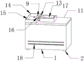
图1为本实用新型一种内置式锂离子蓄电池结构的整体结构示意图。FIG. 1 is a schematic diagram of the overall structure of a built-in lithium-ion battery structure of the present invention.
图2为本实用新型一种内置式锂离子蓄电池结构的俯视结构示意图。Fig. 2 is a top view structural diagram of a built-in lithium-ion battery structure of the present invention.
图3为本实用新型一种内置式锂离子蓄电池结构的仰视结构示意图。Fig. 3 is a structural schematic diagram of a built-in lithium-ion storage battery in the utility model viewed from above.
图4为本实用新型一种内置式锂离子蓄电池结构的爆炸结构示意图。Fig. 4 is a schematic diagram of an explosion structure of a built-in lithium-ion battery structure of the present invention.
图中:1、设备箱体;2、底部支架;3、固定块;4、电池主体;5、正负极接孔;6、正负极标志;7、连接线;8、紧固件;9、触点;10、限位块;11、设备箱盖;12、固定板;13、活动块;14、活动盖;15、透明玻璃层;16、圆形通孔;17、活动把手;18、长形散热孔。In the figure: 1. Equipment box; 2. Bottom bracket; 3. Fixed block; 4. Battery main body; 5. Positive and negative pole connection holes; 6. Positive and negative pole signs; 9. Contact; 10. Limiting block; 11. Equipment box cover; 12. Fixed plate; 13. Movable block; 14. Movable cover; 15. Transparent glass layer; 16. Circular through hole; 17. Movable handle; 18. Elongated cooling holes.
具体实施方式Detailed ways
下面将结合本实用新型实施例中的附图,对本实用新型实施例中的技术方案进行清楚、完整地描述,显然,所描述的实施例仅仅是本实用新型一部分实施例,而不是全部的实施例。基于本实用新型中的实施例,本领域普通技术人员在没有做出创造性劳动前提下所获得的所有其他实施例,都属于本实用新型保护的范围。The technical solutions in the embodiments of the present invention will be clearly and completely described below in conjunction with the accompanying drawings in the embodiments of the present invention. Obviously, the described embodiments are only part of the embodiments of the present invention, not all of them. example. Based on the embodiments of the present utility model, all other embodiments obtained by persons of ordinary skill in the art without making creative efforts belong to the scope of protection of the present utility model.
本实用新型提供了如图1-4所示的一种内置式锂离子蓄电池结构,包括设备箱体1,设备箱体1的底部外壁设置有四组底部支架2,四组底部支架2对称分布在设备箱体1的底部外壁四角,其中使用者可通过设备箱体1底部外壁的四组底部支架2,将设备箱体1抬离地面,避免内部电池受潮,设备箱体1的内部设置有四组固定块3,四组固定块3对称分布在设备箱体1的内部,固定块3的外壁设置有电池主体4,其中使用者可将四组固定块3插接在设备箱体1的内壁,将电池主体4底部外壁插接在固定块3的顶部外壁凹槽内使其固定,电池主体4的顶部外壁设置有两组正负极接孔5,两组正负极接孔5对称分布在电池主体4的顶部外壁两端,正负极接孔5的一侧设置有正负极标志6,正负极接孔5的顶部外壁设置有连接线7,正负极接孔5的内部设置有紧固件8,其中使用者可通过连接线7与两两相隔的电池主体4顶部正负极接孔5相接,扭转紧固件8,使紧固件8可穿过连接线7一侧的金属线圈,与电池主体4外壁的正负极接孔5插接,使四组电池主体4可以相互串联。The utility model provides a built-in lithium-ion battery structure as shown in Fig. 1-4, including an
紧固件8的一侧设置有触点9,其中使用者可将两组触点9底部分别插接在两组电池主体4的正负极接孔5中,将设备箱盖11外壁的两组圆形通孔16插接在触点9外壁,这样使用者可以在设备箱盖11外壁将其它设备与触点9相接,使装置可以正常的运行。One side of the
电池主体4的顶部外壁中间设置有限位块10,设备箱体1的顶部设置有设备箱盖11,设备箱盖11的顶部外壁中间设置有固定板12,其中使用者可通过限位块10插接在四组电池主体4的外壁使其固定,设备箱盖11底部外壁固定的固定板12可插接在限位块10外壁的凹槽内,使限位块10可将电池主体4固定。A limiting
设备箱盖11的顶部外壁设置有活动块13,活动块13的一侧设置有活动盖14,活动盖14的顶部外壁设置有透明玻璃层15,其中使用者可通过活动盖14将突出设备箱盖11外壁的触点9保护起来,避免雨水溅射至触点9上,其顶部外壁的透明玻璃层15可让使用者观察到触点9的情况,且使用者可通过活动盖14一侧的活动块13,使活动盖14可围绕着活动块13上下运行。The top outer wall of the
设备箱盖11的顶部外壁开设有两组圆形通孔16,两组圆形通孔16对称分布在设备箱盖11的顶部外壁两端,其中使用者可将设备箱盖11外壁的两组圆形通孔16,插接在电池主体4上相接的触点9外壁,使装置方便使用者的操作。Two groups of circular through
设备箱盖11的顶部外壁设置有活动把手17,其中使用者可通过拉动活动把手17,将装置提起,使装置方便使用者的移动与携带。The top outer wall of the
设备箱体1的外壁设置有四组长形散热孔18,四组长形散热孔18对称分布在设备箱体1的外壁两端,其中设备箱体1外壁的四组长形散热孔18,可将设备箱体1内部电池主体4工作产生的热量散出。The outer wall of the
工作原理:使用者可通过将四组固定块3插接在设备箱体1的内壁,将四组电池主体4底部插接在固定块3的外壁,使用连接线7将四组电池主体4分别串联起来,扭转紧固件8,使紧固件8可以穿过连接线7相接的铜圈,与电池主体4外壁的正负极接孔5插接,通过两组触点9分别插接在两组电池主体4外壁的正极接孔、负极接孔中,使四组电池主体4形成一个整体,且可将限位块10插接在四组电池主体4的顶部外壁,设备箱体1顶部设备箱盖11底部外壁的固定板12插接在限位块10顶部外壁的凹槽中,使四组电池主体4可固定在设备箱体1内部,且设备箱体1外壁的四组长形散热孔18,可将电池主体4工作产生的热量排出,使装置可以保护电池组的安全;使用者可通过设备箱盖11外壁的两组圆形通孔16,插接在触点9的外壁,使用者可通过触点9给其它装置进行通电,提起设备箱盖11外壁的活动把手17,将装置提起,使装置可以方便移动与携带,且活动把手17一侧的活动块13运行,可将与其相接的活动盖14上下掀动,活动盖14与设备箱盖11相接,可将设备箱盖11外壁圆形通孔16内部的触点9保护,避免雨水溅射其中,或者人员勿碰,造成电池的短路和损坏,使装置更方便使用者的操作,实现了一种内置式锂离子蓄电池结构的高安全性与方便操作功能。Working principle: The user can insert the four sets of fixed
以上显示和描述了本实用新型的基本原理、主要特征和本实用新型的优点。本实用新型要求保护范围由所附的权利要求书及其等效物界定。The basic principles, main features and advantages of the present utility model have been shown and described above. The scope of protection required by the utility model is defined by the appended claims and their equivalents.
Claims (7)
Priority Applications (1)
| Application Number | Priority Date | Filing Date | Title |
|---|---|---|---|
| CN202223352914.3U CN218827623U (en) | 2022-12-14 | 2022-12-14 | Built-in lithium ion storage battery structure |
Applications Claiming Priority (1)
| Application Number | Priority Date | Filing Date | Title |
|---|---|---|---|
| CN202223352914.3U CN218827623U (en) | 2022-12-14 | 2022-12-14 | Built-in lithium ion storage battery structure |
Publications (1)
| Publication Number | Publication Date |
|---|---|
| CN218827623U true CN218827623U (en) | 2023-04-07 |
Family
ID=87252953
Family Applications (1)
| Application Number | Title | Priority Date | Filing Date |
|---|---|---|---|
| CN202223352914.3U Expired - Fee Related CN218827623U (en) | 2022-12-14 | 2022-12-14 | Built-in lithium ion storage battery structure |
Country Status (1)
| Country | Link |
|---|---|
| CN (1) | CN218827623U (en) |
-
2022
- 2022-12-14 CN CN202223352914.3U patent/CN218827623U/en not_active Expired - Fee Related
Similar Documents
| Publication | Publication Date | Title |
|---|---|---|
| ATE492043T1 (en) | LITHIUM ION SECONDARY BATTERY | |
| CN1964126A (en) | Lithium ion secondary battery | |
| CN219575857U (en) | Battery monomer, battery and electric equipment | |
| CN201904409U (en) | Restorable large lithium-ion secondary battery | |
| CN217606982U (en) | Battery and electric equipment | |
| CN119404369A (en) | Battery cells, batteries and electrical devices | |
| US20240250348A1 (en) | Battery cell and battery pack | |
| KR20130047005A (en) | Jelly roll of pouch cell for secondary battery | |
| CN215070127U (en) | Safety protection structure of lithium iron phosphate battery | |
| CN211480949U (en) | A charging device for cylindrical lithium-ion battery | |
| KR100615153B1 (en) | Lithium secondary battery | |
| KR20150033266A (en) | Secondary battery with cooling structure | |
| CN219829978U (en) | Lithium battery state monitoring device | |
| CN111354878B (en) | Case and secondary battery | |
| CN201307623Y (en) | Rechargeable lithium-ion battery without identification of direction of anode and cathode | |
| CN215869712U (en) | Combined small lithium battery | |
| CN207587809U (en) | A new lithium-ion battery pack | |
| CN217983447U (en) | A lithium battery with different charging and discharging ports | |
| CN218548511U (en) | Solid-state lithium battery with positive and negative pole separates keeps off structure | |
| CN111969277A (en) | Lithium battery pack assembly structure | |
| CN214099730U (en) | A new type of 5G communication equipment lithium battery waterproof and moisture-proof protective shell | |
| CN215220847U (en) | Negative electrode structure of power lithium battery | |
| CN220710400U (en) | Battery pack with separated charging and discharging | |
| CN217983453U (en) | A high-safety rolled core lithium-ion battery | |
| CN215869659U (en) | Storage battery pack and communication power supply |
Legal Events
| Date | Code | Title | Description |
|---|---|---|---|
| GR01 | Patent grant | ||
| GR01 | Patent grant | ||
| CF01 | Termination of patent right due to non-payment of annual fee |
Granted publication date: 20230407 |
|
| CF01 | Termination of patent right due to non-payment of annual fee |